As a newbie to everything Propeller, I very slowly set out to integrate the LCD Graphics/Text Driver with a 2.8" LCD, called from a BASIC program, all under flexprop. A month later now, have three nicely animated bar graphs (ea 80 bars) on screen, with 8x8 text number values floating animated, along side each, displaying levels derived from P2 smart pin A/D's (initialized and read from BASIC) with some simple DSP alg's in BASIC to process. BASIC alg uses floating point LOG, and math functions - yet with all this happening, bar graphs can update ~>100 times per second which is plenty fast and look great on the small LCD. Ready for a larger LCD so am in search of a few 4.0" 480x320 ST7796S SPI LCD's with Touch - haven't been able to find these on Amazon or E Bay - does anyone know of a source for these?
BTW, even with my somewhat clunky BASIC code, the speed of this Graphics Driver on the P2 for this sort of application is incredible!..
Yes, if you are using Eric's Flexbasic you have discovered a mighty tool !!
The compiler sneakily uses cache in critical places and gives you amazing speed. Have a look at the 'listing file' from the 'file' menu in the flexprop editor- Its a way of learning prop2 assembler and reveals its secrets.
@tritonium: Thanks for the info on viewing the flexprop 'listing file' will take a look later. Not a software engineer (do mostly RF hardware as an EE), but Eric's Flexbasic reminds me of programming a 1 MHz Apple II many years ago. P2 code execution is maybe 300x faster than the old Apple since running at 300 MHz, so indeed a mighty tool.
Am approaching the point where my Basic code may grow too large and will probably be back here asking what to do next.
I just found the 4" display on AliExpress, but my credit card won't allow the transaction (probably since overseas). So will modify my question - anyone know of a US source for the ST7796S 4.0" LCD's with touch?
I bought mine on aliexpress but i have noticed the 4” seem to be out of stock. I did get find a 3.5” version from the same source. There’s a link in my 4.0” lcd thread.
Unfortunately the link wouldn’t work on my iphone???
Anyway, all the LCDs seem to work with my driver. Only need to set the resolution.
If you have different code, it should also work fine.
Bought a serial 4 inch touch colour lcd from FYD Open Source Hardware (on Aliexpress) back in October for $11, so it seems your supplier is profiting from a shortage in the market with a massive markup!
Supply and demand I guess.
After changing the settings to use the 240x240, I found that I needed to download/run the twice for it to work. Also note the background is white instead of what should be black. Need to investigate further when time permits. I have tried both hardware and software resets, and two resets but this doesn't fix my need to load twice. There is obviously something in the setup that needs changing.
I measured the Vcc current and it is ~13.6mA so I am not powering it with P2 pins at least for now. The 1.44" 128x128 IIRC was around 2mA which is why I powered it from the P1 and P2 pins.
Can somebody please acknowledge if this display should work with Cluso's driver? https://www.buydisplay.com/3-2-inch-capacitive-touchscreen-240x320-tft-lcd-module-display
It has an ILI9341 chipset and 4-wire SPI. What options should I select? resistive touch or capacitive touch controller? Is the font chip option required or are fonts provided by the propeller?
The fonts are provided by the prop. So you are just writing coloured pixels over the SPI bus to the LCD. Almost all the ICs are similar and just work. IIRC the ILI9341 is on one of my displays.
The touch code uses an XC2046? chip which according to that link is resistive. Note I found it to not be super accurate. I think capacitive is supposed to be better but it’s not in my area. Hopefully the code will not be much different.
I'll use the touch feature only for a very simple menu/button selection, not for drawing pictures or anything where exact coordinates matter.
So I'll order some of those. I know there are cheaper offers on Ebay or AliExpress. But I don't want to find out a month later that the dealer is out of business or the display model is no longer produced...
Thanks for the confirmation and, of course, for writing the driver code!
@ManAtWork
Here's video of the display with the xpt2046 touchscreen and it's initial calibration.
I posted that back when I was working on the touchscreen driver...
I've just found this here on GITHUB. Is this the same driver or are there any changes? Which one is the newest version? GIT says V1.0, the one in the first post of this thread has V3.01. All the history/modification info from the source of Greg has been removed.
Ok, I could simply do a pull/fork and compare... But I'm sure others also want to know.
My order from buydisplay has just arrived and I'd like to do some testing...
The driver uses this code to output data to the display:
write           rol     data, #23                       ' prep 9b byte to write (msb first)
                rol     data, #1                wc      ' cmd/data ?
                drvc    #PIN_DC                         ' cmd=0 / data=1
                drvl    #PIN_CE                         ' CS=0
                mov     bits, #8
.nextbit        drvl    #PIN_CLK                        ' CLK=0
                rol     data, #1                wc      ' \ write data bit
                drvc    #PIN_SDA                        ' /  SDA=0/1
                drvh    #PIN_CLK                        ' CLK=1
                djnz    bits, #.nextbit
It's a 5 instruction loop so it executes in ~10 cycles or 50ns at 200MHz. The data sheet of the ILI9341 specifies 100ns minimum cycle time for writes and 40ns minimum SCLK hi/lo times. I wonder that this has not caused any problems so far. The displays seem to work at twice the specified speed.
@ManAtWork said:
The driver uses this code to output data to the display:
write           rol     data, #23                       ' prep 9b byte to write (msb first)
                rol     data, #1                wc      ' cmd/data ?
                drvc    #PIN_DC                         ' cmd=0 / data=1
                drvl    #PIN_CE                         ' CS=0
                mov     bits, #8
.nextbit        drvl    #PIN_CLK                        ' CLK=0
                rol     data, #1                wc      ' \ write data bit
                drvc    #PIN_SDA                        ' /  SDA=0/1
                drvh    #PIN_CLK                        ' CLK=1
                djnz    bits, #.nextbit
It's a 5 instruction loop so it executes in ~10 cycles or 50ns at 200MHz. The data sheet of the ILI9341 specifies 100ns minimum cycle time for writes and 40ns minimum SCLK hi/lo times. I wonder that this has not caused any problems so far. The displays seem to work at twice the specified speed.
I never looked at the timing for P2. I just copied it from my old P1 code and converted it, and not thinking about the P2 running much faster. I have not seen any problems except when trying to read back the data stored in the LCD which failed miserably. I wanted to scroll in landscape mode.
@Cluso99 said:
I never looked at the timing for P2. I just copied it from my old P1 code and converted it, and not thinking about the P2 running much faster. I have not seen any problems except when trying to read back the data stored in the LCD which failed miserably. I wanted to scroll in landscape mode.
Ah, good to know. The data sheet says min. read cycle time is 150ns, so even more than the write cycle time. That would explain why it failed. I just measured with the scope and the actual cycle time is 60ns @200MHz sysclock. The djnz jump takes two more clocks to re-fill the pipeline.
That’s interesting as I thought the jump taken was 2 clocks and not taken was 4 clocks unless not executed because of if_ modifier which is 2 clocks.
Pleased it worked for you What is the size and resolution?
@Cluso99 said:
That’s interesting as I thought the jump taken was 2 clocks and not taken was 4 clocks unless not executed because of if_ modifier which is 2 clocks.
Yes, DJNZ (and similar instruction's) timing is different between P2 and P1. On P1 taking the jump is faster, on P2 not taking it is faster. Normal if_x JMP branches are also slower when taken on P2 vs. same either way on P1.
Thanks. I never noticed the timing difference in Chip’s instruction list.
Makes a good case for using REP when speed is paramount!
use smart pins for SPI data transfers instead of software loop / bit banging. While it works now with some "good luck" some people like to heavily overclock the P2. At 300MHz it is very likely to fail. I also want to use that sort of displays in industrial environments. With smart pins it would be easy to implement a variable divider that self-adjusts to the clock frequency and avoids violation of the display chip timing specs.
If the touch panel code is moved to the PASM cog it would be possible to share the CLK, DIN and DOUT pins of the touch controller with the LCD controller. So only TIRQ and TCS would need extra pins. /RST and LED (backlight on/off) can also share the same pin as they are switched only once for initialisation. This reduces the total pins needed to 8 which is one port of the EVAL or KISS board and is easier to handle.
Some minor optimizations are possible for the DrawLine() and DrawCircle() functions. (they calculate more pixels than neccessary) I plan to use the display for small GUI applications. I think nobody expects it to display videos or animated graphics, so speed optimization is not that important...
For the same reason I think pictures (true color bitmaps) are not really needed (at the moment). But it would be nice to display custom symbols, for example 16x16 tiles at least with two colors. I think this would be not too hard to implement by extending the PaintChar() function from 8x8 to 16x16 and from fixed font to arbitrary images in hubram. 16x16 two color bitmaps can also easily be drawn with "ASCII-arts" in the source code without the need for special conversion tools or SD card data storage.
If you don't mind I'd try to implement those ideas step by step... (I know the source is under MIT licence so I don't have to ask. But I do because if two or more programmers work on the same code simultanously this sometimes causes conflicts)
Edit
...and additionally
provide some way to store calibration data for the touch panel.
OK, smart pin SPI already works. Speed and code size almost stays the same. The time penalty of the reduced (but now correct) clock frequency is compensated by being able to do something else while the smart pins are still busy outputting the last byte of data.
DAT
''+-----------------------------------------------------+
''| PASM LCD Low Level Drivers (separate cog)           |
''+-----------------------------------------------------+
                org     0
entry                                                   ' PTRA contains the pointer to the hub mailbox
                cmp     PIN_3V3_, #64      wc           '\ -1 for non-1.44in LCD
    if_c        cmp     PIN_GND_, #64      wc           '| -1 for non-1.44in LCD
    if_c        drvh    PIN_3V3_                        '| power & gnd for 1.44in LCD only !!!
    if_c        drvl    PIN_GND_                        '/

                drvh    #PIN_CE                         '\ set levels and enable outputs...
                drvh    #PIN_RST                        '|
                drvl    #PIN_DC                         '|
                fltl    #PIN_SDA                        '|
                drvh    #PIN_CLK                        '|
                drvh    #PIN_LED                        '/
                wrpin   modeClk,#PIN_CLK                ' smart pin transition mode
                wrpin   modeTXD,#PIN_SDA                ' smart pin synchronous serial transmit
                wxpin   divCLK,#PIN_CLK                 ' clock transition every 50ns
                wypin   #2,#PIN_CLK                     ' dummy pulse to force IN=1 (ready flag)
...

''+-----------------------------------------------------+
''| LCD Write 8bit CMD/DATA (b8:cmd=0/data=1)           |
''+-----------------------------------------------------+
writedata       or      data, #$100                     ' DC=1=data
writecmd
write           shl     data, #24 wc                    ' prep byte to write (msb first), bit8->C
waitRdy8        testp   #PIN_CLK wz                     ' IN=1 if smart pin ready
        if_nz   jmp     #waitRdy8                       ' wait until last CLK sequence finished
                fltl    #PIN_SDA
                drvc    #PIN_DC                         ' cmd=0 / data=1
                drvl    #PIN_CE                         ' CS=0
                rev     data
                wxpin   #$27,#PIN_SDA                   ' 8 bits, start/stop mode
                wypin   data,#PIN_SDA
                drvl    #PIN_SDA                        ' enable TX smart pin
        _ret_   wypin   #16,#PIN_CLK                    ' start CLK sequence
...
modeCLK         long    P_TRANSITION + P_OE + P_INVERT_OUTPUT
modeTXD         long    P_SYNC_TX + P_OE + P_PLUS1_B + P_SYNC_IO + P_FILT0_AB
PRI drawLine(xs, ys, xe, ye, rgb) | i, x, y
' Draw Line - start co-ords, end co-ords, color
  'plot incrementing x axis
  repeat i from 0 to xe-xs
    y := (ye-ys)*i/(xe-xs)
    drawPixel(xs+i, ys+y, rgb)
  'plot incrementing y axis
  repeat i from 0 to ye-ys
    x := (xe-xs)*i/(ye-ys)
    drawPixel(xs+x, ys+i, rgb)
The old code draws every pixel twice for the worst case of a 45° diagonal line. This can be optimized by inserting an IF statement that executes only the path along the longer axis. Extracting repeating sub-terms furthermore speeds the calculation up by a factor of ~2. Bresenham wouldn't need any divisions or multiplications at all but as there is not much difference in execution time of add/sub to mul/div in Spin I was too lazy to implement that.
PRI drawLine(xs, ys, xe, ye, rgb) | i, x, y, dx, dy
' Draw Line - start co-ords, end co-ords, color
  dx:= xe - xs
  dy:= ye - ys
  if ABS(dx) > ABS(dy)   'plot incrementing x axis
    repeat i from 0 to dx
      y := (dy*i + dx/2)/dx
      drawPixel(xs+i, ys+y, rgb)
  else 'plot incrementing y axis
    repeat i from 0 to dy
      x := (dx*i + dy/2)/dy
      drawPixel(xs+x, ys+i, rgb)
Proper rounding (dx/2 term) results in equally spaced steps instead of a 1-pixel spike at the end point.
I know, it's only a demo. So please don't take that as critizism. I just can't leave sub-optimum code as it is when I see it, same as I can't resist solving a scrambled Rubik's cube.
PRI drawCircle(xc, yc, dia, rgb) | x, y
' Draw Circle d^2 = x^2 + y^2; y = SQRT(d^2 - x^2) (Pythagoras theorum)
  repeat x from 0 to dia
    y := SQRT((dia*dia) - (x*x))
    'plot 4 quadrants for incrementing x axis
    drawPixel(xc+x, yc+y, rgb)
    drawPixel(xc-x, yc+y, rgb)
    drawPixel(xc+x, yc-y, rgb)
    drawPixel(xc-x, yc-y, rgb)
    'plot 4 quadrants for incrementing y axis (fills in more dots on circle)
    drawPixel(xc+y, yc+x, rgb)
    drawPixel(xc-y, yc+x, rgb)
    drawPixel(xc+y, yc-x, rgb)
    drawPixel(xc-y, yc-x, rgb)
"dia" is actually the radius. "repeat x from 0 to dia" calculates too much pixels (full quadrant along X axis). You can stop as you reach 45° (one octant) so "repeat x from 0 to dia/sqrt(2)" would be sufficient.
PRI drawCircle(xc, yc, r, rgb) | x, y
' Draw Circle d^2 = x^2 + y^2; y = SQRT(d^2 - x^2) (Pythagoras theorem)
  repeat x from 0 to r
    y := SQRT((r*r + r/2) - (x*x))
    if y < x
      quit ' octant finished
    'plot 4 quadrants for incrementing x axis
    drawPixel(xc+x, yc+y, rgb)
    drawPixel(xc-x, yc+y, rgb)
    drawPixel(xc+x, yc-y, rgb)
    drawPixel(xc-x, yc-y, rgb)
    'plot 4 quadrants for incrementing y axis (fills in more dots on circle)
    drawPixel(xc+y, yc+x, rgb)
    drawPixel(xc-y, yc+x, rgb)
    drawPixel(xc+y, yc-x, rgb)
    drawPixel(xc-y, yc-x, rgb)
The r/2 term also fixes the one-pixel spike at the extreme points (12, 3, 6 and 9 o'clock). The circles now look much "rounder".
@ManAtWork
All changes, fixes, optimisations are greatly appreciated.
Yes, I recall realising I was using radius and calling it dia. However I missed fixing it.
I am also aware (I have a test v3.03) where I realised I set CS but never turn it off.
One last comment, if you combine pins, please leave the option to keep them separate. I use the LCDs with a single row of pins and they plug straight into my RetroBlade2. I haven’t been in need of saving pins with P2 yet.


Comments
I recently bought a 1.3" 240x240 SPI color LCD and a 3.5" 480x320 SPI color LCD. I haven't had a chance yet to try with my driver - it should just be a simple parameter change.
https://aliexpress.com/item/4000838271820.html
https://aliexpress.com/item/4001122632293.html
As a newbie to everything Propeller, I very slowly set out to integrate the LCD Graphics/Text Driver with a 2.8" LCD, called from a BASIC program, all under flexprop. A month later now, have three nicely animated bar graphs (ea 80 bars) on screen, with 8x8 text number values floating animated, along side each, displaying levels derived from P2 smart pin A/D's (initialized and read from BASIC) with some simple DSP alg's in BASIC to process. BASIC alg uses floating point LOG, and math functions - yet with all this happening, bar graphs can update ~>100 times per second which is plenty fast and look great on the small LCD. Ready for a larger LCD so am in search of a few 4.0" 480x320 ST7796S SPI LCD's with Touch - haven't been able to find these on Amazon or E Bay - does anyone know of a source for these?
BTW, even with my somewhat clunky BASIC code, the speed of this Graphics Driver on the P2 for this sort of application is incredible!..
@ synetcom
Yes, if you are using Eric's Flexbasic you have discovered a mighty tool !!
The compiler sneakily uses cache in critical places and gives you amazing speed. Have a look at the 'listing file' from the 'file' menu in the flexprop editor- Its a way of learning prop2 assembler and reveals its secrets.
Dave
@tritonium: Thanks for the info on viewing the flexprop 'listing file' will take a look later. Not a software engineer (do mostly RF hardware as an EE), but Eric's Flexbasic reminds me of programming a 1 MHz Apple II many years ago. P2 code execution is maybe 300x faster than the old Apple since running at 300 MHz, so indeed a mighty tool.
Am approaching the point where my Basic code may grow too large and will probably be back here asking what to do next.
I just found the 4" display on AliExpress, but my credit card won't allow the transaction (probably since overseas). So will modify my question - anyone know of a US source for the ST7796S 4.0" LCD's with touch?
I bought mine on aliexpress but i have noticed the 4” seem to be out of stock. I did get find a 3.5” version from the same source. There’s a link in my 4.0” lcd thread.
@Cluso99: I found this 4" LCD display with touch based on ST7796S that appears in stock: https://www.aliexpress.com/item/4000234986822.html
Now working with a friend to purchase a few for me - earliest delivery April 20. It looks like it should work OK with the Graphics Driver, you think?
Unfortunately the link wouldn’t work on my iphone???
Anyway, all the LCDs seem to work with my driver. Only need to set the resolution.
If you have different code, it should also work fine.
Ray,
If there is still more to figure out, you might want to grab the source for the Micromite/Armmite. They have done extensive work with these displays.
Regards,
Craig
Hi
Bought a serial 4 inch touch colour lcd from FYD Open Source Hardware (on Aliexpress) back in October for $11, so it seems your supplier is profiting from a shortage in the market with a massive markup!
Supply and demand I guess.
Dave
Ouch. Just managed to follow the link.
I paid ~$12 for both 4” and 3.5” 480x320 SPI shipped. All prices seem to be rising but $50 is ridiculous..
Just tried my 1.3" 240x240 ST7789
After changing the settings to use the 240x240, I found that I needed to download/run the twice for it to work. Also note the background is white instead of what should be black. Need to investigate further when time permits. I have tried both hardware and software resets, and two resets but this doesn't fix my need to load twice. There is obviously something in the setup that needs changing.
I measured the Vcc current and it is ~13.6mA so I am not powering it with P2 pins at least for now. The 1.44" 128x128 IIRC was around 2mA which is why I powered it from the P1 and P2 pins.
Can somebody please acknowledge if this display should work with Cluso's driver?
https://www.buydisplay.com/3-2-inch-capacitive-touchscreen-240x320-tft-lcd-module-display
It has an ILI9341 chipset and 4-wire SPI. What options should I select? resistive touch or capacitive touch controller? Is the font chip option required or are fonts provided by the propeller?
The fonts are provided by the prop. So you are just writing coloured pixels over the SPI bus to the LCD. Almost all the ICs are similar and just work. IIRC the ILI9341 is on one of my displays.
The touch code uses an XC2046? chip which according to that link is resistive. Note I found it to not be super accurate. I think capacitive is supposed to be better but it’s not in my area. Hopefully the code will not be much different.
I'll use the touch feature only for a very simple menu/button selection, not for drawing pictures or anything where exact coordinates matter.
So I'll order some of those. I know there are cheaper offers on Ebay or AliExpress. But I don't want to find out a month later that the dealer is out of business or the display model is no longer produced...
Thanks for the confirmation and, of course, for writing the driver code!
@ManAtWork
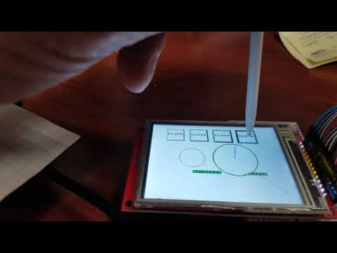
Here's video of the display with the xpt2046 touchscreen and it's initial calibration.
I posted that back when I was working on the touchscreen driver...
I've just found this here on GITHUB. Is this the same driver or are there any changes? Which one is the newest version? GIT says V1.0, the one in the first post of this thread has V3.01. All the history/modification info from the source of Greg has been removed.
Ok, I could simply do a pull/fork and compare... But I'm sure others also want to know.
My order from buydisplay has just arrived and I'd like to do some testing...")
The driver uses this code to output data to the display:
write rol data, #23 ' prep 9b byte to write (msb first) rol data, #1 wc ' cmd/data ? drvc #PIN_DC ' cmd=0 / data=1 drvl #PIN_CE ' CS=0 mov bits, #8 .nextbit drvl #PIN_CLK ' CLK=0 rol data, #1 wc ' \ write data bit drvc #PIN_SDA ' / SDA=0/1 drvh #PIN_CLK ' CLK=1 djnz bits, #.nextbitIt's a 5 instruction loop so it executes in ~10 cycles or 50ns at 200MHz. The data sheet of the ILI9341 specifies 100ns minimum cycle time for writes and 40ns minimum SCLK hi/lo times. I wonder that this has not caused any problems so far. The displays seem to work at twice the specified speed.
v3.01 is the latest. See the first post")
I never looked at the timing for P2. I just copied it from my old P1 code and converted it, and not thinking about the P2 running much faster. I have not seen any problems except when trying to read back the data stored in the LCD which failed miserably. I wanted to scroll in landscape mode.
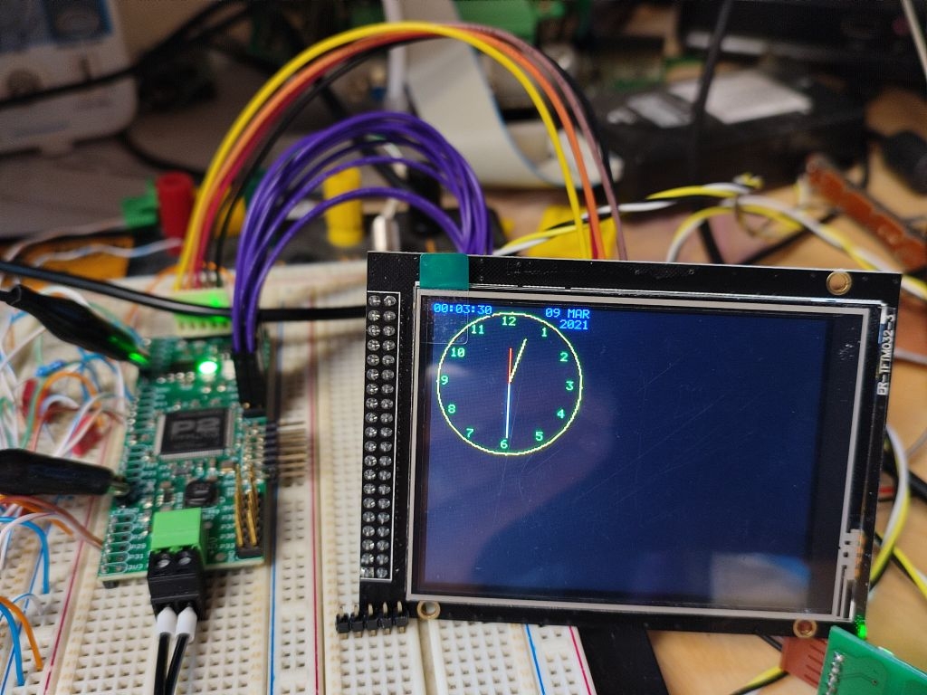
Jipeee! Works at the first go:
Ah, good to know. The data sheet says min. read cycle time is 150ns, so even more than the write cycle time. That would explain why it failed. I just measured with the scope and the actual cycle time is 60ns @200MHz sysclock. The djnz jump takes two more clocks to re-fill the pipeline.
That’s interesting as I thought the jump taken was 2 clocks and not taken was 4 clocks unless not executed because of if_ modifier which is 2 clocks.
Pleased it worked for you") What is the size and resolution?
What is the size and resolution?
Yes, DJNZ (and similar instruction's) timing is different between P2 and P1. On P1 taking the jump is faster, on P2 not taking it is faster. Normal
if_x JMPbranches are also slower when taken on P2 vs. same either way on P1.Thanks. I never noticed the timing difference in Chip’s instruction list.
Makes a good case for using REP when speed is paramount!
I have some ideas for improvements to the driver.
If you don't mind I'd try to implement those ideas step by step... (I know the source is under MIT licence so I don't have to ask. But I do because if two or more programmers work on the same code simultanously this sometimes causes conflicts)
Edit
...and additionally
So yes, I can confirm that it works.") Pleased to use your work.
Pleased to use your work.
OK, smart pin SPI already works. Speed and code size almost stays the same. The time penalty of the reduced (but now correct) clock frequency is compensated by being able to do something else while the smart pins are still busy outputting the last byte of data.
DAT ''+-----------------------------------------------------+ ''| PASM LCD Low Level Drivers (separate cog) | ''+-----------------------------------------------------+ org 0 entry ' PTRA contains the pointer to the hub mailbox cmp PIN_3V3_, #64 wc '\ -1 for non-1.44in LCD if_c cmp PIN_GND_, #64 wc '| -1 for non-1.44in LCD if_c drvh PIN_3V3_ '| power & gnd for 1.44in LCD only !!! if_c drvl PIN_GND_ '/ drvh #PIN_CE '\ set levels and enable outputs... drvh #PIN_RST '| drvl #PIN_DC '| fltl #PIN_SDA '| drvh #PIN_CLK '| drvh #PIN_LED '/ wrpin modeClk,#PIN_CLK ' smart pin transition mode wrpin modeTXD,#PIN_SDA ' smart pin synchronous serial transmit wxpin divCLK,#PIN_CLK ' clock transition every 50ns wypin #2,#PIN_CLK ' dummy pulse to force IN=1 (ready flag) ... ''+-----------------------------------------------------+ ''| LCD Write 8bit CMD/DATA (b8:cmd=0/data=1) | ''+-----------------------------------------------------+ writedata or data, #$100 ' DC=1=data writecmd write shl data, #24 wc ' prep byte to write (msb first), bit8->C waitRdy8 testp #PIN_CLK wz ' IN=1 if smart pin ready if_nz jmp #waitRdy8 ' wait until last CLK sequence finished fltl #PIN_SDA drvc #PIN_DC ' cmd=0 / data=1 drvl #PIN_CE ' CS=0 rev data wxpin #$27,#PIN_SDA ' 8 bits, start/stop mode wypin data,#PIN_SDA drvl #PIN_SDA ' enable TX smart pin _ret_ wypin #16,#PIN_CLK ' start CLK sequence ... modeCLK long P_TRANSITION + P_OE + P_INVERT_OUTPUT modeTXD long P_SYNC_TX + P_OE + P_PLUS1_B + P_SYNC_IO + P_FILT0_ABI'll post the full code when I'm finished.
PRI drawLine(xs, ys, xe, ye, rgb) | i, x, y ' Draw Line - start co-ords, end co-ords, color 'plot incrementing x axis repeat i from 0 to xe-xs y := (ye-ys)*i/(xe-xs) drawPixel(xs+i, ys+y, rgb) 'plot incrementing y axis repeat i from 0 to ye-ys x := (xe-xs)*i/(ye-ys) drawPixel(xs+x, ys+i, rgb)The old code draws every pixel twice for the worst case of a 45° diagonal line. This can be optimized by inserting an IF statement that executes only the path along the longer axis. Extracting repeating sub-terms furthermore speeds the calculation up by a factor of ~2. Bresenham wouldn't need any divisions or multiplications at all but as there is not much difference in execution time of add/sub to mul/div in Spin I was too lazy to implement that.
PRI drawLine(xs, ys, xe, ye, rgb) | i, x, y, dx, dy ' Draw Line - start co-ords, end co-ords, color dx:= xe - xs dy:= ye - ys if ABS(dx) > ABS(dy) 'plot incrementing x axis repeat i from 0 to dx y := (dy*i + dx/2)/dx drawPixel(xs+i, ys+y, rgb) else 'plot incrementing y axis repeat i from 0 to dy x := (dx*i + dy/2)/dy drawPixel(xs+x, ys+i, rgb)Proper rounding (dx/2 term) results in equally spaced steps instead of a 1-pixel spike at the end point.
I know, it's only a demo. So please don't take that as critizism. I just can't leave sub-optimum code as it is when I see it, same as I can't resist solving a scrambled Rubik's cube.
PRI drawCircle(xc, yc, dia, rgb) | x, y ' Draw Circle d^2 = x^2 + y^2; y = SQRT(d^2 - x^2) (Pythagoras theorum) repeat x from 0 to dia y := SQRT((dia*dia) - (x*x)) 'plot 4 quadrants for incrementing x axis drawPixel(xc+x, yc+y, rgb) drawPixel(xc-x, yc+y, rgb) drawPixel(xc+x, yc-y, rgb) drawPixel(xc-x, yc-y, rgb) 'plot 4 quadrants for incrementing y axis (fills in more dots on circle) drawPixel(xc+y, yc+x, rgb) drawPixel(xc-y, yc+x, rgb) drawPixel(xc+y, yc-x, rgb) drawPixel(xc-y, yc-x, rgb)"dia" is actually the radius. "repeat x from 0 to dia" calculates too much pixels (full quadrant along X axis). You can stop as you reach 45° (one octant) so "repeat x from 0 to dia/sqrt(2)" would be sufficient.
PRI drawCircle(xc, yc, r, rgb) | x, y ' Draw Circle d^2 = x^2 + y^2; y = SQRT(d^2 - x^2) (Pythagoras theorem) repeat x from 0 to r y := SQRT((r*r + r/2) - (x*x)) if y < x quit ' octant finished 'plot 4 quadrants for incrementing x axis drawPixel(xc+x, yc+y, rgb) drawPixel(xc-x, yc+y, rgb) drawPixel(xc+x, yc-y, rgb) drawPixel(xc-x, yc-y, rgb) 'plot 4 quadrants for incrementing y axis (fills in more dots on circle) drawPixel(xc+y, yc+x, rgb) drawPixel(xc-y, yc+x, rgb) drawPixel(xc+y, yc-x, rgb) drawPixel(xc-y, yc-x, rgb)The r/2 term also fixes the one-pixel spike at the extreme points (12, 3, 6 and 9 o'clock). The circles now look much "rounder".
@ManAtWork
All changes, fixes, optimisations are greatly appreciated.
Yes, I recall realising I was using radius and calling it dia. However I missed fixing it.
I am also aware (I have a test v3.03) where I realised I set CS but never turn it off.
One last comment, if you combine pins, please leave the option to keep them separate. I use the LCDs with a single row of pins and they plug straight into my RetroBlade2. I haven’t been in need of saving pins with P2 yet.
@ManAtWork
Here are some circle drawing routines I was playing with that use the cordic functions...