LoRa Robot - Rock Crawler Edition
 xanadu
Posts: 3,347
xanadu
Posts: 3,347
Hello fellow Forumistas! I am back with another four wheeled robot build. This time with somewhat realistic goals!
Features:
- Redcat Racing Everest 1:10 Scale RC Rock Crawler
- LoRa Radio 915mhz (Heltec ESP32 with OLED) DIY 915mhz antenna
- 5.8ghz video and audio link
- Ultra-low lux camera
- Propeller 1
- SK6812W LEDs
- Expanded PCV platform
- Portable Control Station, video link and LoRa link over USB to any computer
I chose the RC crawler https://www.redcatracing.com/products/everest-10-1-10-scale-crawler-2-4ghz because it is slow and can handle terrain well. There is an easy conversion kit to four-wheel steering.
The plan is to revisit building a semi-autonomous rover that can be left outside for long periods of time. Now that I have an area to do such a thing, unlike my last, “we’ll just leave it on park land indefinitely and hope for the best” solar powered rover.
I am at the point of having something worth posting. We do not need solar power although I am toying with the idea of wireless charging via a solar powered dock. As is, with the right power management this could spend days out in the woods.
The expanded PVC platform and matching acrylic dome are a work in progress. Before I get to that I would like to see how much space I need. The Propeller Project board will likely be replaced with a Prop Mini or Flip. The camera needs a pan/tilt mount. The antennas need better mounting.
I have driven the robot into the woods and covered a 3 acre area exploring during the day, and once at night during a thunderstorm. All from the comfort of my alternate home office. I find it highly entertaining and much better than anything on TV.
More to come, it took me over a week just to write this… I know my priorities are out of whack!
Here's my DIY antenna. If you're wondering why the soldering is so bad, I did this with a TS80!!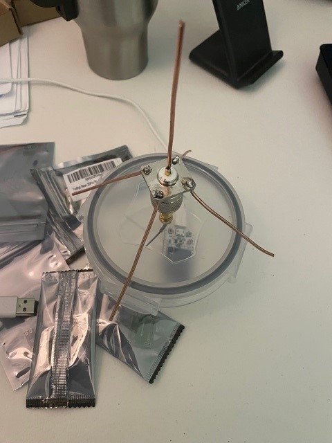
This is how the ePVC attaches to the chassis. This is just a prototype so yeah, it's a little sloppy.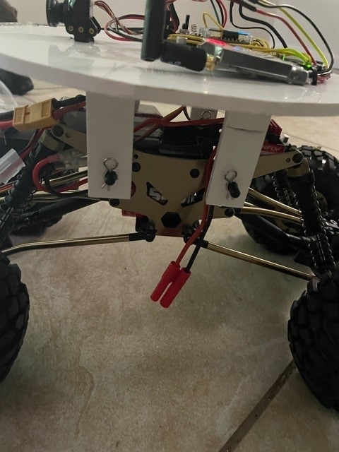
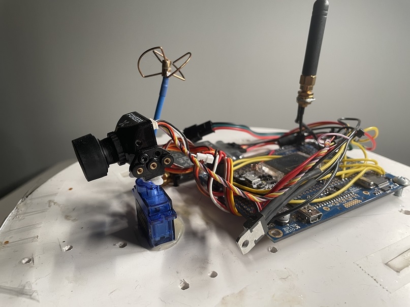
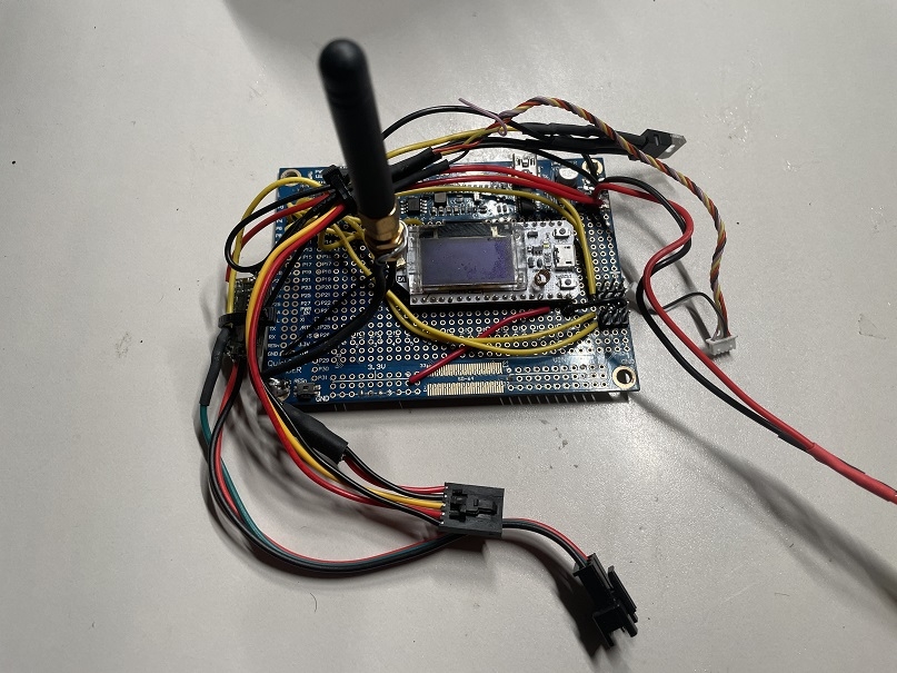
Here we have the Heltec board mounted to a Propeller Project board. There's a small perfboard holding a 5V supply for the LEDs, and a FET to control power to the video transmitter. A tiny little Foxeer low lux camera, and the 5.8ghz video transmitter, with built-in microphone. 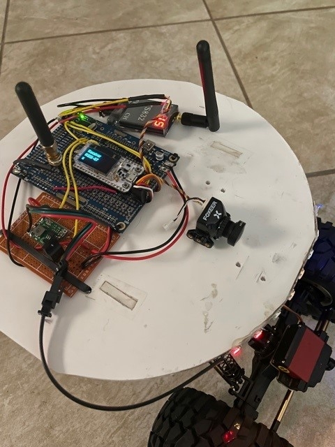
It is starting to look like a robot.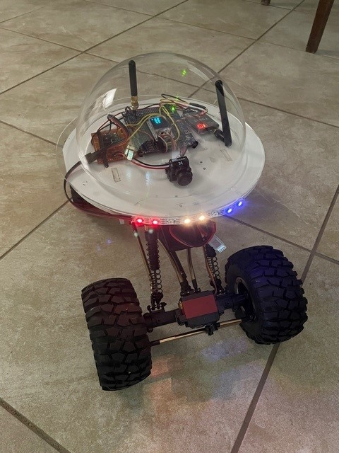
Comments
Goal 1, find out if LoRa radios are good for controlling robots. Use your favorite search engine for more LoRa and LoRaWAN details. People do amazing long range things with them.
LoRa is short for Long-range Radio. It uses little power and can go extremely far with the right modules and antennas. Ideally, you would use them for IoT sensors that spend most of their life in a low power sleep mode.
Instead of using a proper LoRa module, I opted for some cheap Heltec Boards with ESP32, small OLED screen and not so great RF components. I did this because I never thought they would leave my desk. I wanted to play around with packet headers, and eventually LoRaWAN, crypto, and other misc. items like making my own antennas. It did not take long before I wanted to control a robot. I will eventually get proper LoRa modules and connect them directly to the P1.
The first consideration when using LoRa for remote control is that the radio is half-duplex. When it comes to the robot going out of range, there are issues to deal with. We cannot measure RSSI without sending or receiving a packet. Because the radios must flip flop between tx and rx modes, the round trip time for a packet to go to the robot and get our acknowledgement is a couple of seconds. That means we get an RSSI reading every 1-2 seconds, providing we send data that frequently. To deal with that we simply drive slowly, and spam commands that do not do anything (to measure RSSI).
In addition, we have a hard limit of the robot’s receiver RSSI of -140 or below programmed to stop the robot and then reverse movement direction for 2 seconds. At this point, the transmit power of the control station is increased and we get the robot back into a stronger signal area. The control station antenna is stronger, so we would likely lose our ack packet on the return side before we lost control of the robot itself.
Why not just make it so the robot can only move a few feet at a time? I tried that and it is annoying and with the right antennas you need not worry about range.
The second consideration is that you will be limited to a low data rate. Text yes, video no. No problem for me.
Using the Arduino IDE, I was able to write code for the Heltec ESP32 control station (PC running Putty serial terminal) and the robot. Both sides are in a receive loop waiting for packets. The transmitter breaks out of the receive loop when it receives serial input via Putty. It then transmits the input and switches back to receive mode.
On the robot side the receiver receives the transmission and send it to the Propeller 1 serial connection. It then changes to transmit mode and sends an “ack” packet. Literally, it sends the letters a, c, and k. The ack packet triggers a response in the Putty terminal showing the command sent, SNR and RSSI values.
Example line from Putty – “x SNR 11.25 RSSI -76”. The command sent was “x” followed by SNR and RSSI.
The minimum RSSI required for packets to flow is -142. The RSSI will often spike below this well before it becomes a steady reading. That gives me an early indication we are close to the maximum range.
It is important to note that my SNR and RSSI are the values of the control station transmitter receiving a packet from the robot. I could program it to work either way, however my control station has a better antenna and more power, so I am showing the worst-case scenario by measuring the return trip. By the way, this info is also displayed on the OLED displays : ) Having the little displays is perfect for debugging.
Pros: Long Range, Low Power, Small, Inexpensive
Cons: Half-duplex, Low Bandwidth, Slow
Dang! That's exactly the bot I needed in my crawlspace awhile back:
https://forums.parallax.com/discussion/173366/robotic-raccoon-cam
-Phil
I'll add a camera retrieval arm and ship it out : )
Video of rock crawling action. Next up, work on video antennas and repeaters. The video signal is poor because there is no line of sight. Instead of running wires outside of the house I'll just repeat the signal on another channel.
Impressive!
-Phil
Amazing work!
Thanks.
Status... waiting for parts.
Current mission: Checking the hive. It's hot and they're bearding. It's fun to watch but sometimes I don't want to be eaten alive by mosquitoes.
Here's a screen capture of the highest latency remote control you'd probably ever want.
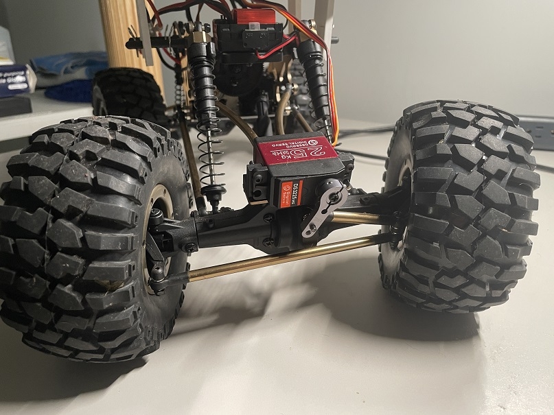
The rear servo is installed and programmed. It was fun to setup. The pan servo for the camera is installed as well. This makes it easy to manually drive, combined with the go almost anywhere chassis, it's a lot of fun.
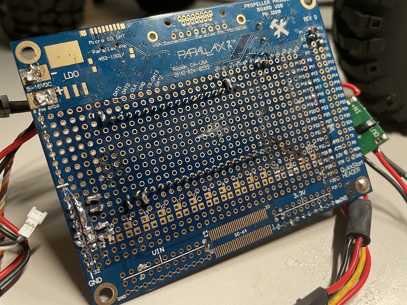
I spent about a week not looking at this project because of an intermittent short on the P1 board. There was no magic smoke, I discovered it with my DMM. Eventually I scraped the bottom of the P1 board with a razor between all of the connections until it went away.
The crawler is maneuverable enough to make it autonomous (goal 2). The thought of soldering anything else to the P1 board is a bit overwhelming. I've used and abused this board and I think that it's time to replace it. The e-pvc platform is quickly running out of space and I've got antennas that need better placement.
The plan is to 3D print a better designed platform to hold new sensors. I don't think the 6" clear dome will make the final cut. I would like to design a PCB with sockets for everything. It would be nice to have a FLIP, and break out the IO pins on a professionally printed PCB.
This cheap RC truck is a steal when it comes to an all terrain chassis. I'm going to focus on making a 3D printed kit that will convert a 1:10 scale RC vehicle into a robot, and a companion PCB to plug everything into.
Rear wheel servo and linkages-
This is a mess...
Another mess...
The pan servo-