

P2ME2 - (was Bypass capacitors needed for P2)
 rogloh
Posts: 6,312
rogloh
Posts: 6,312
I'm currently laying out my own P2 board to replace the now absent P2D2 I'd otherwise planned to use and am having issues fitting in a total of 32 bypass caps just for the P2 on the PCB, given I will likely have to hand solder them and really don't want to go below 0603 sized parts to help save my eyes.
In practice would a P2 really need that many bypass capacitors if the supply is kept very close to the P2?
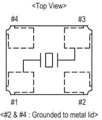
In this case the core voltage is fed from a ring around the inner ground square and probably only needs to travel about 5mm from the regulator outside the ring. A ground plane is on the rear side and the bypass caps are wired directly to the inner square on the rear side with a via on each 1.8V pin. The 3.3V bypass caps are on the same side as the P2 but it's a bit of a squeeze to try to fit them all in with all the signals fanning out between them but I'm still trying and may get there anyway with 6/6 design rules. I'm not planning to spend weeks laying out this board to make it fit nicely. It's likely a one off.
If any caps need to get removed for space reasons, which supply, 3.3V or 1.8V, would the impact typically be less noticeable?
Update: forgot to mention, this is a two layer board which is why it is more challenging.
Comments
I think its the 1v8 rail, and the 3v3 around V2831 (that does the PLL) that would matter most. The remaining 3v3 caps are mostly going to improve analog performance
You probably want do the pads there, regardless of whether you end up loading them with caps or not
LOL. Unfortunately fitting in all 0603 pads is the hard part and can mess up the clean tracks. It's tight to route with 16 caps on a single layer with the signals as well and you certainly end up shuffling the signal tracks around a lot by hand. It's probably achievable with enough time. Here's the general (and incomplete) picture of how it is progressing. 1.8V bypass caps are in the center (white), 3.3V bypass cap pads are shown in blue below. On a two layer board using a P2 the trick seems to be getting the 3.3V plane to somehow feed all the VCCIO pins without cutting off ground current pathways as well. Lots of via stitching is probably needed somewhere.
I designed my board(s) for best practices. Unfortunately you don't know what the end user will use the P2 for, nor which pins for what.
Therefore I put bypass caps on all supply pins, and bulk caps around the ends of each line (4 lines around the chip). This is overkill but works really well as you know. Which ones can be removed is a little more complex. Possibly every second one per rail would be just fine in my case as I have good rails around the chip. Also, perhaps one corner for the bulk could be removed ie keep just two opposite corners with them. But do remember, I don't use switchers which cause more noise.
I decided not to place caps on the underside as I didn't want them to fall off when I reflow the other side, and also I wanted a place to put a heatsink if required.
We do know that the 3V3 for P28-31 also drives the PLL, so this needs to be ultra quiet. So you need a 100nF on the VIO pin and a bulk cap 4u7F (or larger) closeby unless you have a really good track to where the bulk cap is placed, and decoupling along the way. An extra 10nF may even be better here.
Thanks Cluso. Yeah I'm trying to get them all to fit. I suspect they will in the end. I've been able to clean up my tracks and there appears to be (just) enough room with 6/6 rules and 0603 cap footprints. If I had all 32 of them all on the same layer I'd be in trouble, but the 1.8V bypass caps are on the other side thankfully.
I'll pay attention to the PLL supply pin too. I do have a 3.3V LDO linear regulator fitted but it's at the top of the board. Maybe I can route a trace from it down to this VIO supply pin which could help reduce supply noise.
You've got 16 caps on VDD (1v8), that's a lot. I'd say you can safely drop every second one.
How many VIO (3v3) rails are there? Looks like just one. One cap in each corner is probably enough for that then.
It is a lot. I guess I don't have to fit them all though. The footprint will be there. If heat is an issue I have a fan option blowing air onto the P2 chip so a heatsink on the back surface is not required and I can fit the 1.8V bypass caps there.
Yeah one 3.3V rail for now, unless I bring down my quieter linear regulator output for the PLL supply voltage.
Caps on the rear side certainly help lower inductances, as well as allowing larger caps.
Does it have to be 2L ? 4 Layers is not that much more on small boards, and the thermal and impedance performance is a lot better.
Yeah it needs to be 2 layers as that is the layout software limit (free).
You are using Eagle, right? There are older versions that have a layer limit of 4 and a size limit of 100x80mm. I stil use V3.5 which I find much more usable as it doesn't suffer from feature-itis as newer versions do.
To answer the original question: If you plan to use the board only by yourself you can leave out every second bypass cap as long as you don't do extreme things like driving parallel busses at high speeds (toggling many pins at the same time) or otherwise generate lots of noise. But if you plan to release the design as general purpose board you'll never know what abuse the end user does. Overclocking, bad pin assignment (check out this)...
Yeah it's on version 6.5 I think.
Thanks. I am planning to hopefully be able to drive 18 bit parallel LCD with ~40 - 50MHz pixel clock signals so I think I would need the bypass caps on VIO (at least on all those video groups). I want to get the bypass pads down at least. Mostly fitting I think but my 3.3V power and ground planes are probably going to be fighting it out for space on the non-component side. I want the 3.3V net to have a bit of space for the regulator's inductor to dissipate its heat - which is where I ran into issues on the board this will plug into earlier.
As I discovered the original PLL issue on the P2 boards, it would be somewhat ironic if it happened to my board too. But with my inexperienced circuit board layout skills I can't rule it out... Maybe I should think about a 20MHz oscillator. Good thing is those P28-31 pins are likely going to be for (relatively) slow SD card pins in my circuit, so not especially high speed compared to memory bus access and they might not all switch at once - just two signals probably switch at any time (SPI clock and data, and probably at different phases anyway).
Just as a FYI: I used to use Eagle, but now am very happy with the free KiCAD. That doesn’t suffer from such limitations.
Yeah have been considering trying Kicad out sometime, I'm just so used to Eagle now and can get things done with it and can create my own components etc, so there's a bit of inertia not to change - though the whole rental model has me interested in abandoning it once I want to do more complex or commercial boards that need the full version unless I decide to go 3d printer as well sometime down the track with its Fusion360 integration. I think I preferred Eagle before it went down its new path.
Update: This P2 board is mainly for this project which has been on hold waiting for P2D2 all this time:
https://forums.parallax.com/discussion/comment/1461433/#Comment_1461433
Components including 3D Models works well in kicad. And the PCB with components can be exported as STEP allowing for further processing in 3D software. I’m really happy with that. But it certainly is a plunge. IMHO worth it though.
Another approach here would be to do a simple P2-Edge to P2D2 adaptor ? The P2 Edge has the higher Vin capability you need. (but does lack USB-UART).
Yeah that was my first thought and lacking a USB-UART is fine as I do that function on my own carrier board. However I am space constrained in the enclosure and there just doesn't seem to be the clearance in all dimensions. It's quite close though. I'll take a photo later when I can. The Edge board itself would fit in the space pretty nicely, but it's connector is too large to mount down the side I want and would probably also cause all the signals to cross in any adapter board too. I do hope to use the PSRAM based Edge in the next one if I can though.
@JRoark , answering your question from the other thread here. It was a IOT5500 board from Peter Jakacki and it could be optionally mated to his custom P1 board as well. Not sure if these particular things are still available or not.
Internally it's just a Wiz5500 based board but the bonus is it's low profile and can be reverse mounted. There are some others like it on Ebay these days too I think. eg. lookup:
HR961160C USR-ES1 W5500
Does it matter if the VIO supply voltage or 1.8V core comes up first if the P2 is held in reset throughout? I have my 3.3V switcher output powering the input to the 1.8V switching regulator and the PG signal output of 1.8V regulator controlling the reset of the P2, so it will only enable the P2 once the 1.8V core voltage is fully up. By the time as the 1.8V switcher starts up, which is 1.25ms after it's enabled by the 3.3V supply, I think its 3.3V input voltage should already be stable because this 3.3V switcher has an UVLO if its input voltage is below 4V.
I was looking at the power section of the P2-EVAL rev C schematic and it doesn't seem to have any circuitry that delays the VIO or VCORE voltage supply startup times apart from whatever the regulators already inherently do internally. So I'm hoping the architecture I have planned is sufficient for starting up a P2.
Here's the intended schematic. The i2c hotswap part is optional but could help fix a potential issue I envisage in my own setup when the P2 is powered down. The input protection is on the carrier board so is not duplicated here. VIN could potentially be connected to 5VON as well in 5V only setups and I'll probably put a jumper on the board in order to do that. In my system I can use it as a shutdown/sleep signal which also powers the low noise LDO.
Note: R4 and R3 resistor values are reversed, I've fixed it since.
@rogloh said:
Good deal. That ethernet interface board wasnt something I had seen before, which begged the question.
I've mostly done the PCB now. Here are the two sides of the PCB shown as overlayed gerbers using the Gerbv tool.
The board is intended to be reverse mounted (with a fan blowing air upwards) so in this case the "bottom" of the PCB has the P2 fitted and the top faces out. I added an LED for power and solder jumpers to bypass the i2c hotswap switch and to strap 5V to VIN in 5V only setups.
I tried to pay attention to regulator heat dissipation by adding lots of micro vias in heated regions and leave more copper where I could though it's a challenge with only two layers and multiple power planes. We'll see where we end up. The 3.3V switcher's inductor I selected is only 1/4 of the resistance to my last one so with any luck that will help keep it cooler this time when pushing 2A through it. I do have that fan option now too.
Looks good. I might move the inductor further from the Xtal, as the xtal pins are proven sensitive nodes.
The worse current waveforms are on C43/C20, so they may be better on the same side as U1 ?
Yep I didn't like how close that inductor was getting either. I am still playing around with that lower part and could change it some more and perhaps try to add another bypass cap to the PLL supply pin too as Cluso mentioned while I'm at it.
It's turning out quite a challenge, at least for me, to get reasonably sized components for hand soldering (apart from the tiny 1.8V switcher) to all fit on a two layer board at this small P2D2 size and still try to leave enough copper to help cooling, but I'd still like to prove to myself it can be done. Hopefully by separating the two switching regulators and placing them above and below the P2 where there is still some free copper on one layer will spread out the heat a bit further over the total PCB area.
What really amazes me are the sheer number of capacitors needed for such a basic P2 board like this - around 45 caps!
Made some minor tweaks. Moved the inductor a fraction further away, grounded the extra crystal pads, added another bypass cap pad for the PLL VCCIO supply, and added more thermal/electrical vias for the P2 exposed pad. It should transfer heat better now I believe. I also fixed the solder paste area so it wasn't one entire square of paste in the middle but broken into smaller squares separated from the vias in case I decide to make up and use a stencil.
This is passing the DRC again now so I think I'll probably just send this one off as it is. The 3.3V switching regulator stuff is still rather close to the crystal for my liking so we'll see how much noise that introduces. The crystal is shielded in its can and now grounded too at least and the XI / XO signals wires are surrounded by grounds on top and bottom layers so I'm not sure what else I can do with those really on a two layer board.
Do you need a 0v test pin to connect oscilloscopes to without risk of shorts?
Yeah good idea, I could try to squeeze a ground test point loop near the prog plug perhaps or below the LED. There's not that much free copper left now really. It looks large scaled up but when you shrink the image size down to 40x55mm you realize just how compact the P2D2 dimensions really are.
The XI signal is the most sensitive node, so maybe that trace can be given top priority ?
It would help to also allow a footprint for a CMOS Oscillator, as that would be more tolerant of the inductor large-swing coupling effects - Xtals and OSC can share a common GND pin 2, and pin4 can optionally link to 3v3 then Pin 3 -> XI and a jumper can isolate XO
Are you sure that xtal footprint is correct ?
XI path is fairly well protected and I think the footprint I have used is okay for a crystal. The crystal is on the bottom layer so the pads are reversed when looking through the board. I'll look into the dual footprint concept with an oscillator. Pin 4 is really close to the 3.3V supply, so it might be achievable with a solder jumper. I guess I have to remove XO path with a jumper.
Ahh, right, I missed the mirror reverse plot.
I think so, as P2 lacks any XI active with XO floated mode
@jmg I have added support for an oscillator to be used now. It will default to a crystal if the board is used as is. Pin 4 is NC unless a jumper is soldered, at which point it is fed 3.3V. I also added a bypass cap for it too. The XO signal is routed from the P2 to the crystal but this track can be cut if an oscillator is fitted instead of a crystal - there is a re-solderable pad there too for that as well in case the track cut needs restoration. See below, the transparent lower blue layer can be seen below the red layer, via feeds power to pin 4.
That looks nice and flexible")