

P2 ADC timing
 pic18f2550
Posts: 400
pic18f2550
Posts: 400
in Propeller 2
Hello,
How many clocks are needed for an 8 or 16 bit conversion?
Thank you.
Comments
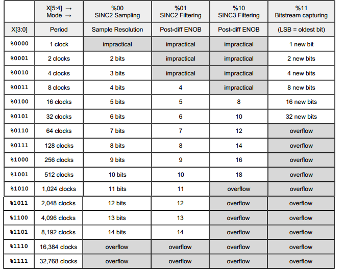
Depends on the ADC mode. Here is the table from the documentation:
Does the ADC take a sample?
Or do analogue value fluctuations have an effect on the conversion?
It's a Sigma-Delta ADC, so it measures the average voltage over the sample periode.
Ok.
So the input does not have a sample & hold circuit.
The counter always runs behind the measured value.
If the input signal changes relatively slowly, higher resolutions in shorter periods would also be possible.
Correct on both.
Yes, and the Sinc3 mode is fastest. Limited by the first-order sigma-delta loop I think. Chip mentioned somewhere around 1 MHz, from memory.
There is a DC noise floor that isn't particularly great though. The reason is a little beyond my understanding. If you don't need DC then it performs well.
The SincN accumulating counters are 27-bit wide. In Sinc3 mode, that caps the decimation period to max of 512 bit-clocks, or 2^(27/3). For an internal bitstream, from the internal ADC, that's 512 sysclocks. Decimation period is settable with WYPIN, after the WXPIN.
In Sinc2 "filtering" mode it is a max of 2^(27/2), or 11585 bit-clocks.
PS: The 27-bit width of "filtering" modes need an additional treatment that's not documented. Without the treatment they will sporadically glitch. I haven't fully got to the bottom of it but I have noticed the glitching is amplitude sensitive.
The fix is to always eliminate the higher significant bits, over 27, from the 32-bit handling of the decimation. This can be either done as shift left by five, scaling to 32-bit, or by zeroing the upper five bits of the post-diff'ed sample.
There is a handy instruction just for zeroing -
ZEROXThe DC noise occurs when the counter changes its counting direction.
It tends to drift around the switching threshold of the comparator.
This is usually only one or two bits.
It's much worse than that. Chip refers to it as 1/f noise. The largest decimation periods don't provide any improvement in ENOB.
I'm guessing that adding some fancy low-pass digital filtering can help some, but I fear it won't be nearly as much as a it would if the DC noise wasn't so bad. I keep meaning to get extra filtering running myself but my knowledge of frequency analysis is very limited so I don't have an end method in mind.
The ENOB numbers in the table above probably only apply in a bandpass above 10 Hz or so.
If I understand the above table correctly, I can achieve with a processor clock of 256Mhz, with SINC3 500.000 measurements with 18bit resolution.
Is that correct? Is there also a code snippet?
More than 18 bits are apparently not available.
I don't know how those ENOB numbers/equations were arrived at. The smartpin sinc2/sinc3 filters operate up to 27-bit. The sigma-delta ADC, however, peters out at around 12-bit. Maybe 14-bit for a higher pass-band.
No. You can expect 11 to 12 bits at 256MHz with 256 clocks SINC3 filtering. If you need higher resolution I recommend adding an external ADC. The PCM1807 for example costs <$1 and offers 24 bits resolution at 100kSamples/s and typically 99dB SNR.
This is theoretical ENOB. In reality, these ADCs introduce noise, which reduces their real resolution to 11..12 bits.
Where's the theory for that statement? Only google results on ENOB I've found are about the analogue factors.
Ok, it looks like the problem cannot be solved with internal means.
I have picked out the MCP3911.")
It supports 24-bit resolution.
Let's see if I understand the documentation correctly.
Do you have any experience with this part or a code snippet to help me understand it?
Interesting, the MCP3911 datasheet is hinting, for its 24-bit claim, at the same theoretical limit equation as above. Which suggests it internally has 36-bit accumulators for its sinc3 filters.
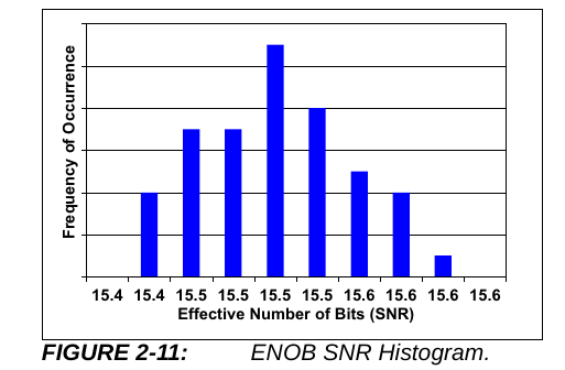
And importantly there is a graph for ENOB, two graphs in fact. Both indicating around 15-bit limit. So nowhere near the 24-bit poster claim:
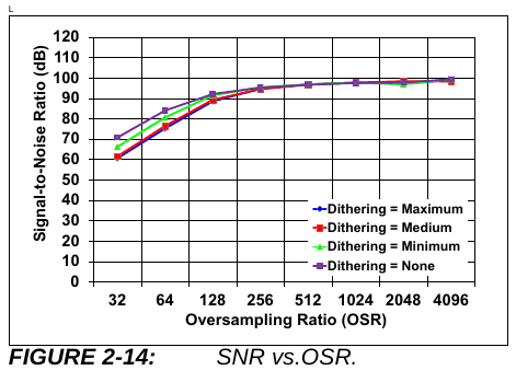
EDIT: And the other relevant graph is the decimation/sampling period. Which shows analogue factors being dominant from 256 clocks and above:
Can an external sigma-delta modulator like the AMC1035 or AMC1106 be used with internal sinc3 filtering for better ENOB?
Yes, smartpin mode P_ADC_EXT (%11001).
And can even do it as sinc1 with smartpin mode P_REG_UP (%01100).
EDIT: Err, my "yes" is just meaning it will work. When you ask if it's better ENOB ... better compared to what? Ah, compared to the Prop2 internal ADCs ... well, you'd think so but maybe only when making use of the common-mode isolation. In ideal conditions the SNR is only around 85 dB. Which is still only 13 to 14 bits effective.
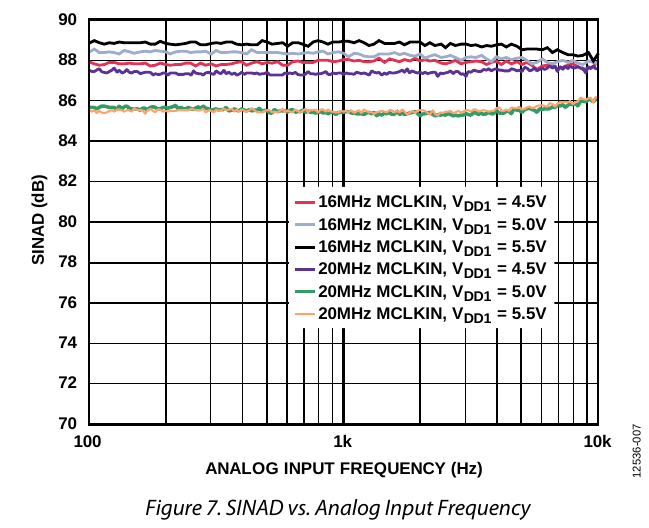
AD7405 is a little better. Notably it improves with the lower 16 MHz clock frequency. One wonders if, say, 10 MHz would be even better.
I always wonder a bit what people expect from ADCs. I find the internal ones quite acceptable for audio.
I have written a test program here that allows to sample short audio snippets into the Hubram, and listen to them again and also save them as WAV file via the fileserver of flexProp onto the PC. Recording and playback is done via the same stereo jack (my board has only one audio port).
To use the memory well I use only 16bit mono samples, and only with 48 kHz. The ADCs could also do 18bit at 384 kHz, or more.
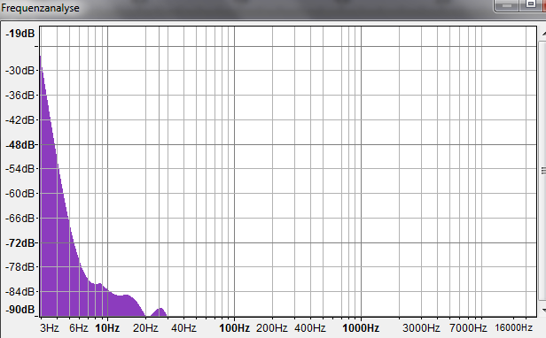
In the ZIP file there are 2 WAV files, one with music, and one with silence. In the latter one you can judge the noise level well. Additionally I analyzed the frequency response with Audacity, the result is visible in the diagram. However, I do not know how meaningful this kind of measurement and analysis is, compared to the diagrams from the data sheets of the above ADCs.
It's been a learning experience for me, for sure. I did a little testing with them quite a while back but, not knowing what to expect, got disheartened when not achieving the estimated 18-bit spec in the docs, let alone what sinc3 appeared to offer numerically.
I suspect even Chip was unsure how all this filtering was meant to pan out.
EDIT: In hindsight, I realise now the ADCs were designed when Chip only understood sinc1. There wasn't any expectation, on his part, of more than 12-bit sampling really. And even that wouldn't be fast enough for audio.
EDIT2: You're right. 12-bit ain't shabby.
If that's correct it is highlighting what we've been calling "drift" I think. I'm guessing that if your graph went below 1 Hz it would probably flatten out. At what dB level is the question.
The routines used for rapid calibration on every sample were designed to remove that noise component while still providing accurate DC readings for instrumentation use.
Ariba,") It stops hard at 90 dB though.
It stops hard at 90 dB though. 
Can you run that analysis again with more vertical range? I want to see the floor at 100 Hz. Never mind, found I already have Audacity.
Yeah thats because this are 16bit samples = 96 dB max. For more dB I would need to sample with 18 bits and produce a WAV with 24bit samples for Audacity.
Audacity is saying it is 32-bit float internally. And I've resaved it as such too. File size doubled. Nothing about the waveform datatype makes any change to that spectrum graph.
You get not more information than is in the 16bit samples, also if you convert it to 32-bit float.
Ariba wenn ich dich richtig verstehe kann ich mit einer
_clkfreq = 256_000_000 '500kHz * 512
einen 18 Bit Wert mit 500Khz Abtastrate machen?
That only affects where the plotted floor would appear, not the graph bounds. And it's that very plotted floor I'm wanting to see! Granted, it might be a false floor, but Audacity isn't showing it.
The good news is if that spectrum is right then frequencies above ~20 Hz are 15+ ENOB.
Hmm, Ariba, just trying to use your code ... but can't work out where this
fs9p.ccfile is. Only occurrence in Eric files is a cryptic reference within include/filesys/fs9p/fs9p_internal.h. I tried replacing the filename with filesys/fs9p/fs9p_internal.cc but this generates a parameter mismatch warning ...... although it did compile. But test waveform wasn't written, it seemed to open but not close it. Stayed at zero size.
Using
loadp2 -9 .