

Something rather strange in Pulse/Cycle Smartpin mode output
 rogloh
Posts: 6,390
rogloh
Posts: 6,390
I've encountered some weird Smartpin behavior and I don't quite understand it. Really hoping it is not a P2 HW bug in the REV B chip. Maybe I'm doing something wrong or not following when it is meant to trigger.
I can't get a reliable start of the pulse output mode once I trigger it. It seems to do strange things with values of WXPIN=3 and higher once it is triggered, and also it offsets its starting output pulse by another P2 clock with each increasing values after 4. The change from X=3 to X=4 looks weird too as it seems to lose a couple of offset clocks in the process. I've hacked up a test program that can be used to display a reference clock pattern on one clock output P2 pin along with the pulse output on another P2 pin and triggered by a serial keypress so you can see it happen on a scope/logic analyser. I'm running slow at 3.33MHz to help with this. I was also wondering if I was resetting things correctly each iteration or if not everything resets fully when the Smartpin is floated low.
A simple test program to see this behaviour is attached (runs with fastspin/flexgui etc). You can customise the two P2 output pins if you'd like. With the serial console you can press a digit from 1-9 to set the X value for the WXPIN parameter directly, then hit space to start the pulse output with that WXPIN value and see it on a scope with the reference clock pulses to trigger on. You can also press , . characters to decrease or increase X and < > characters to decrease/increase the Y value used (for WYPIN), though for this test I just leave Y at 1 which is its default. You can also uncomment the two PASM lines to get a single high pulse at the start of the pulse sequence (the compare value in the high word is then set as one less than the low word of the WXPIN value) and also see it moving along as you increase X - it also has the strange behavior at X=2,3,4 etc.
Do other people see this on their device setups? Am I doing something wrong in the code preventing it to work correctly?
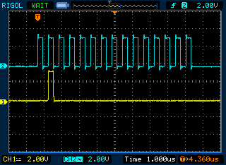
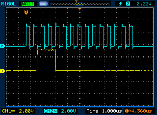
Below are my scope grabs for each increasing value of X (With WYPIN set as #1 here). Yellow is the Pulse Smartpin and Cyan is the reference clock pulse train (generated around the same time in the code). From X=5 and higher things stabilise and the clock moves by one P2 clock each time it increases (not sure why), as well as it's total duration (which I do expect).
WXPIN param = 1
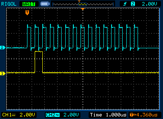
WXPIN param = 2
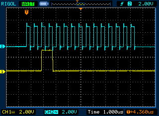
WXPIN param = 3
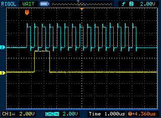
WXPIN param = 4
WXPIN param = 5
Sample test code below. Hopefully your serial port still works at this low P2 clock rate (my MAC did). If not you might just need to slow down the baud rate.
Roger
I can't get a reliable start of the pulse output mode once I trigger it. It seems to do strange things with values of WXPIN=3 and higher once it is triggered, and also it offsets its starting output pulse by another P2 clock with each increasing values after 4. The change from X=3 to X=4 looks weird too as it seems to lose a couple of offset clocks in the process. I've hacked up a test program that can be used to display a reference clock pattern on one clock output P2 pin along with the pulse output on another P2 pin and triggered by a serial keypress so you can see it happen on a scope/logic analyser. I'm running slow at 3.33MHz to help with this. I was also wondering if I was resetting things correctly each iteration or if not everything resets fully when the Smartpin is floated low.
A simple test program to see this behaviour is attached (runs with fastspin/flexgui etc). You can customise the two P2 output pins if you'd like. With the serial console you can press a digit from 1-9 to set the X value for the WXPIN parameter directly, then hit space to start the pulse output with that WXPIN value and see it on a scope with the reference clock pulses to trigger on. You can also press , . characters to decrease or increase X and < > characters to decrease/increase the Y value used (for WYPIN), though for this test I just leave Y at 1 which is its default. You can also uncomment the two PASM lines to get a single high pulse at the start of the pulse sequence (the compare value in the high word is then set as one less than the low word of the WXPIN value) and also see it moving along as you increase X - it also has the strange behavior at X=2,3,4 etc.
Do other people see this on their device setups? Am I doing something wrong in the code preventing it to work correctly?
Below are my scope grabs for each increasing value of X (With WYPIN set as #1 here). Yellow is the Pulse Smartpin and Cyan is the reference clock pulse train (generated around the same time in the code). From X=5 and higher things stabilise and the clock moves by one P2 clock each time it increases (not sure why), as well as it's total duration (which I do expect).
WXPIN param = 1
WXPIN param = 2
WXPIN param = 3
WXPIN param = 4
WXPIN param = 5
Sample test code below. Hopefully your serial port still works at this low P2 clock rate (my MAC did). If not you might just need to slow down the baud rate.
Roger
CON

   CLK3_3MHz  = %1_001001_0000110001_1110_10_00 '(20MHz/10) * 50/30 = 3.3   MHz
   CLK200MHz  = %1_000100_0000110001_1111_10_00 '(20MHz/5)  * 50/1  = 200   MHz


  _clkmode = CLK3_3MHz ' setup a slow clock for testing
  _clkfreq = 3_333_333
'  _clkmode = CLK200MHz ' setup a full speed clock
'  _clkfreq = 200000000


   baud = 230_400
   rx_pin = 63
   tx_pin = 62
   pulsepin = 42
   clkpin = 40


OBJ
    ser: "SmartSerial"

PUB start
    ' setup some default startup clock - use slowest clock for logic analyzer
    clkset(_clkmode, _clkfreq)
    coginit(cogid, test, @teststack)

PUB test | id, x, y, c
    ser.start(rx_pin, tx_pin, 0, baud)

    id := cognew(@testcode, @mbox1)

    waitcnt(cnt + _clkfreq)

    x := 1
    y := 1
    ser.printf("COG %d spawned\nX=%d, Y=%d\n",id, x,y)

    repeat
        c:=ser.rx
        if c == " "
            ser.printf("Triggering Smartpin Pulse Output (X=%d, Y=%d) ... ",x,y)
            ser.printf("result = 0x%x\n", send(x,y))
        else
           if c > "0" AND c =< "9"
              x:=c-48
           elseif c == ">"
              y++
           elseif c == "."
              x++
           elseif c == "<"
              if y > 1
                 y--
           elseif c == ","
              if x > 1
                 x--
           ser.printf("X=%d Y=%d\n", x, y)


PUB send(a,b)
    long[@mbox2] := b
    long[@mbox1] := a
    repeat until long[@mbox1]==0
    return long[@mbox2]


DAT
        orgh

mbox1       long 0
mbox2       long 0
teststack   long 0[100]

'-------PASM COG testing code-----

testcode
                org

                fltl    #pulsepin
                fltl    #clkpin
                wrpin   #%1_00101_0, #clkpin  ' set clkpin into Smartpin transition output mode
                wxpin   #1, #clkpin           ' transition delay = 1 P2 clock
                drvh    #clkpin               ' prepare a clock reference output

wait            rdlong  data, ptra            ' poll mailbox
                tjz     data, #wait
                rdlong  data2, ptra[1]        ' read second param

                fltl    #pulsepin             ' reset smartpin
                wrpin   #%1_00100_0,#pulsepin ' configure RWDS smartpin for pulse output

'               setword data, data, #1        ' these 2 lines can be enabled to get single high pulse
'               sub     data, ##$10000

                wxpin   data, #pulsepin       ' set the X timing parameter
                wypin   #0, #pulsepin         ' clear the Y timing parameter to be sure it won't trigger
                drvl    #pulsepin             ' enable RWDS smartpin

                wypin   #30, #clkpin          ' show some reference clocks for triggering scope/logic analyzer
                wypin   data2, #pulsepin      ' now set the Y timing parameter to start the pulse output

                waitx   #100                  ' wait for the test to complete/settle
                fltl    #pulsepin             ' reset smartpin

                wrlong  #0, ptra[1]           ' return a value if needed for testing etc
                wrlong  #0, ptra              ' clear mailbox
                jmp     #wait                 ' repeat

data  long 0
data2 long 0
Comments
Ok so perhaps then the Smartpin trigger time is sensitive to its value in the X register as it is enabled and the time between enabling the Smartpin and setting its Y value to 1 to start the next cycle. In my code above that corresponded to 4 clock cycles. This may be why cycles with X register values of 1 and 2 and 4 started right away as they are multiples factors of 4. 3 is not a multiple factor of 4 and would have to wait until its multiple of clock cycle offset 6 (2 away from 4), and all others greater than 4 would offset by X-4 clocks from the starting time. This seems to line up with the images and seems right.
I am hoping there is a way to trigger the pulse sequence either when the Smartpin enabled or when I send the Y value but IIRC when I set Y to 1 before the Smartpin is enabled to force it to output as soon as it is enabled I don't think I get any pulse (but I will double check this and report back when I retest that sequence, as I've already tried a bunch of things that didn't work out).
Basically I'm trying to get a one-shot output pulse behavior happening at some given time after I issue the command. I can tolerate and compensate for a fixed output pulse timing offset, but not a variable one.
Chip got away with not having to worry about it in his flash boot/programming code because he's operating at sysclock/2 only. In his case, using smartpin "transition" mode, means the timebase is sysclock. Which in turn means there is no timebase phasing.
WXPIN data, #pin
WYPIN #1, #pin
before I enable the pin with
DRVL #pin
Nothing appears on the pin. There doesn't seem to be a way to start it until after the Smartpin is enabled and then you set the Y register, and at this point some number of clocks have already elapsed which will affect the output pulse duration because it won't always be a multiple of the desired interval at that clock cycle and you have to wait for the interval to elapse. I also thought of starting with WXPIN #1, #pin first so it reloads on every cycle, and then setting X properly after the pin is enabled but it doesn't help either.
It appears somewhat Chicken-egg for generating one-shot pulses of a variable duration.
Why can't Y be setup before the smartpin is enabled in this mode so output can startup right away when you need it to?
Here's some notes from back in 2017 that I remember touched on this issue.
https://forums.parallax.com/discussion/comment/1416568/#Comment_1416568
Ok then it looks like this type of issue has been confusing people in the past as well. I still don't know why setting WYPIN=1 can't be done before the Smartpin is enabled so the output sequence can be starting right away. It just doesn't output anything in that case and waits for Y to be written AFTER the Smartpin is enabled, but by then some clocks have already elapsed.
I'm hoping to use the Smartpin to control RWDS. It will be great if it works but I'm having problems fitting it into the overall sequence with these limitations and variable latencies etc. Main problem left now with my workaround above is not causing a bus clash if I enable the Smartpin output too soon. I have to delay it until after the HyperRAM address phase finishes.
Coordinating all this timing/latency stuff certainly accelerates the aging process.
Not fun until it all works.
Yes, the ideal would be an ARM then GO model. It seems some aspects of init, have missed getting that GO to apply, and so they start early (before the GO )
Perhaps Y is simply always being reset right at the enabling of the Smartpin in this mode by the HW. Maybe a small oversight or design flaw there (no offence Chip!)
As the documentation states:
During reset (DIR=0), IN is low, the output is low, and Y is set to zero.
To me this reads as an asynchronous clearing of the Y register when the smartpin is disabled.
Your post title states pulse/transition mode, but the documentation has pulse/cycle mode and transition mode as separate items.
In pulse/cycle mode with X[31:16] set to 0, X[15:0] set to pulse duration+1, and Y to 1, you should get a high output from the WYPIN until X[15:0]-1 sysclocks later.
Is this not the case?
Yes Y is being reset (as you point out it's actually documented which I'd misinterpreted as cleared when entering reset, but not held in reset) while the Smartpin is reset. Before even knowing that I was hoping we could use it to start the output cycle at a precise time, but it can't be done and it needs to count through the first counter sequence before it will begin its output.
You get the correct output but you have to wait for an initial X sequence (or a multiple of them) to complete after releasing the Smartpin from reset before the new Y setting is honoured.
It appears I can get it down to supporting 4 latency clocks with this Smartpin code I am playing with. Doing 3 is too tight with this code unless I can find a way to overlap/optimize further. In any case 4 will be okay in the near term, as the ISSI HyperRAM always doubles its minimum 3 clock latency setting up to 6 because it is locked in fixed latency mode, and the HyperFlash is 5 clocks minimum. However other devices might possibly be faster one day.
The ISSI octalRAM has these tables. They support 3, but only to 83MHz bus speed, which may give your code more time ?
I might be able to look at a way to tighten it up if I can as I do have a few nops left in there, but for now it is 4 latency clocks minimum.
Does this ISSI octaRAM still only use fixed latency like their HyperRAM I wonder or can it be variable latency as well? The IS66WVH16M8ALL/BLL part doesn't support variable latency even though there is a register setting bit for it.
I actually thought about this too, and it might, but the Parallax board doesn't have it.
EDIT: actually I see it does have a resistor, it's 10 ohms.
If the smartpin was 'idling' on a base period of 1 sysclock and Y = 0, then for each pulse you could set X to a preamble value giving enough time to immediately set X to the pulse length, and set Y to 1. Then set X back to give the short base period again.
Timed correctly the preamble base period should expire as Y is set to 1, giving the pulse duration high and then back to a short idle value.
So values for X could be:
idling - $0000_0001 'base period counter is reloaded every sysclock
preamble - $0000_0004 'base period counter is reloaded after 4 sysclocks
pulse - $0000_0000 | pulse_length 'output high when Y > 0, pulse is full length of X[15:0]-1
Sequence for a pulse might be:
WXPIN preamble, #pin 'idling, so base period counter is reloaded with low word of preamble immediately
WXPIN pulse, #pin 'base period counter preamble - 2, X contains pulse for next period
WYPIN #1 , #pin 'base period counter is reloaded to pulse_length; start pulse
WXPIN idling, #pin 'at end of pulse go back to short idle with output low
The numbers might be slightly off, but I think the concept is sound.
Edit:
Thinking about this further, maybe the preamble isn't needed. Just extend the pulse value by 2 to account for the time taken to set Y.
So:
idling - $0000_0001 'base period counter is reloaded every sysclock
pulse - $0000_0000 | pulse_length 'output high when Y > 0, pulse is length of X[15:0]-3
WXPIN pulse, #pin 'idling, so base period counter is reloaded with low word of pulse immediately
WYPIN #1 , #pin 'start pulse, base period counter is pulse_length - 2
WXPIN idling, #pin 'at end of pulse go back to short idle with output low
@jmg, I was able to tighten the code for 3 clock cycle latency with RWDS but it offset my streamer data by a whole clock. There is lots of work to do around the same time unfortunately. I'm still working on it...
Another complexity is that the data sheet seems to imply you have to set RWDS low first before you can drive it high (see note 5 below). I don't like this and would like to drive it high first which is easier in the code the way the one shot works. I wonder if it really is required. Maybe the memory device senses the low condition first somewhere in case you leave it floating high or something...?
You could drive it low sooner? It's tri state for quite a few clocks.
I do hope the memory shuts off RWDS just after the falling edge of the third clock in time. It's not specified in the data sheet unfortunately but I'm guessing that would trigger it. Enabling the RWDS output here is about as late as I can manage it.
Also I have found I can get latency=3 operation now too which is a bonus, so @jmg should be pleased.
EDIT: Hmm, spoke to soon. I think my data is offset wrong again now - I need a proper 4 channel scope! Sick of not seeing data and RWDS and clock all together and only seeing two of these signals at once. Maybe I will switch to my logic analyser. The scope is handy though for seeing the tri-state level. I guess I can hook up both tools to the same pins.
Scope mode on four channels with a video display connected to the P2 was demonstrated by Chip a while back. Would that work for you?