

Halloween Hex
 Duane Degn
Posts: 10,588
Duane Degn
Posts: 10,588
So what does one do when they have too many unfinished projects? That's right, start another project.
As a break from programming my mini hexapod, I started working on a larger hexapod.
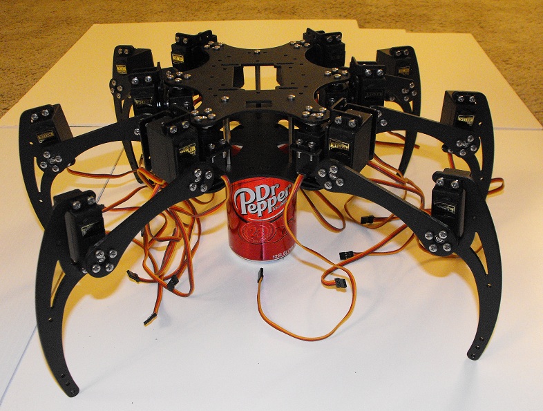
I blame Bill Henning for this one. A while ago he started building a hexapod from a kit he purchased on ebay. I had previously purchased enough HXT12K servos to rebuild my Popsicle Stick Hexapod with stronger servos. Seeing Bill's hexapod made me think maybe a kit from ebay wasn't such a bad idea.
The ebay kit arrived about a month ago but I didn't start putting the kit together until a couple of days ago. It was a pretty quick build once I found some instructions and gave up on trying to use the nuts and bolts which came with the kit. Fortunately I had a bunch of M3 hardware I had purchased from Micro Fasteners. I listed the various machine screws, nuts and washers I used to complete the kit in this blog on Let's Make Robots.
I'm hoping to have this up and running by Halloween. My wife suggested using it to bring the candy bowl up to the Trick O' Treaters when they come knocking on the door.
One of the big challenges with a hexapod this size is providing enough power to all 18 servos. I've ordered serveral different voltage regulators off ebay hoping they will be able to meet the current demands of the hexapod.
So far, I've only had one leg move at a time using a servo tester. I'll try to find a way to provide enough power to move all the legs even if it needs to be tethered for now.
I'm going to keep a table of contents to this thread here. I'll reserve a few of the first few posts so I can keep important information easy to find near the top of the thread.
Post #1 Intro, table of contents.
Post #2 Reserved for videos.
Post #3 Reserved for software.
As a break from programming my mini hexapod, I started working on a larger hexapod.
I blame Bill Henning for this one. A while ago he started building a hexapod from a kit he purchased on ebay. I had previously purchased enough HXT12K servos to rebuild my Popsicle Stick Hexapod with stronger servos. Seeing Bill's hexapod made me think maybe a kit from ebay wasn't such a bad idea.
The ebay kit arrived about a month ago but I didn't start putting the kit together until a couple of days ago. It was a pretty quick build once I found some instructions and gave up on trying to use the nuts and bolts which came with the kit. Fortunately I had a bunch of M3 hardware I had purchased from Micro Fasteners. I listed the various machine screws, nuts and washers I used to complete the kit in this blog on Let's Make Robots.
I'm hoping to have this up and running by Halloween. My wife suggested using it to bring the candy bowl up to the Trick O' Treaters when they come knocking on the door.
One of the big challenges with a hexapod this size is providing enough power to all 18 servos. I've ordered serveral different voltage regulators off ebay hoping they will be able to meet the current demands of the hexapod.
So far, I've only had one leg move at a time using a servo tester. I'll try to find a way to provide enough power to move all the legs even if it needs to be tethered for now.
I'm going to keep a table of contents to this thread here. I'll reserve a few of the first few posts so I can keep important information easy to find near the top of the thread.
Post #1 Intro, table of contents.
Post #2 Reserved for videos.
Post #3 Reserved for software.
Comments
Hardware
1 x Hexapod kit from ebay
72 x 5mm M3 machine screws (two bags)
12 x 6mm M3 machine screws
78 x 8mm M3 machine screws (two bags)
96 x M3 nuts (two bags)
24 x M3 washers
Servos
18 x HXT12K Metal Gear Servos from HobbyKing
Power
Yet to be decided LiPo battery pack. Either 2S or 3S.
Yet to be decided voltage regulators.
Here are a couple I plan to try.
12A Switching Regulator from ebay
15A Switching Regulator from ebay
8A Switching Regulator from HobbyKing
I'll likely use more than one regulator on the robot. Bajdi on Let's Make Robots use one of the HobbyKing regulator for each pair of legs.
Electronics
I haven't decided on the electronics yet.
The hexapod will (of course) be controlled with a Propeller but I don't know which Propeller board I'll use.
I have one of Bill Henning's RoboPi boards which I may use with this robot.
I may use a QuickStart board with some added servo connectors as I used with my Popsicle stick hexapod. I have several Propeller Proto Boards I might use.
Sensors
I haven't decided on which sensors to use with this robot yet. One of the reasons I wanted to make a larger hexapod was so it would have the capacity to carry extra sensors.
The legs have several mounting holes near the tips of the feet. It would be really interesting to add some sort of touch feedback to the feet.
I didn't want to use LockTite on machine screw securing the flanged bearing to the servo bracket. I decided to use two nuts to hold the bearing in place so the nuts could be tightened against each other.
I took some photos of the assembly process.
Here are the parts used.
There are two M3 nuts. M3 washers are used on either side of the bearing. A 12mm long M3 machine screw was required to hold all these parts.
Once all the parts were added, I finger tightened the nuts and then used a combination of needle nose pliers and adjustable wrench to tighten the nuts against each other.
The main problem with using this technique is the extra nut makes the assembly protrude from the bottom of the hexapod an extra 2mm. IMO, the extra 2mm isn't a problem and I'd rather use two nuts the mess around with Locktite (which always seems to have dried out when I need it and it also gets places where I don't want it).
VERY COOL!
You are making my itch to resume working on HexPi worse!!!
:-)
Looks like you managed to get exactly the same chassis, but in black, I may need to get a black one too. I agree, the screws/nuts that come with the kit are sub-par, but I was reasonably happy with the aluminum pieces. I will be following your build with great interest.
I am especially curious as to how your servos will work, if they work well, perhaps I'll upgrade HexPi
What's the reason for not using the nylon-insert lock nut? They're usually more reliable than two nuts together (though a split washer between can help that).
Yes, I'll probably use two or three.
Even on my small hexapod I use two regulators for the servos.
Now you tell me. It always seemed the two nuts held pretty well so I used two nuts. I don't have enough experience with lock nuts to know how well they work.
I'm pretty sure I have at least six M3 nuts with nylon inserts. I'll use those.
I read split washers are next to worthless for holding nuts in place? I thought NASA did a study on them and found they basically act as a normal washer. I didn't hear this directly from NASA so my source could have been mistaken.
A good split washer should provide added torque against the nut to help keep things in place, and is intended to have the same pre-stressing effect that rebar does with concrete. Their stressed condition is when they are flattened. Also, at least theoretically, if a nut starts to loosen, there's torque still applied by the washer as it expands, providing a little bit of fail-safe. Of course, at some point, as the nuts spread too far the gap will eventually become too large. I didn't read this supposed NASA study, but the effectiveness of all fasteners depends on size, load, and application. Taken outside of context every type of fastener has its limitations.
I started using nylon-insert locking nuts when I found a cache of my two most commonly used sizes -- 2/56 and 4/40 -- at a local surplus warehouse. I buy hardware by the pound, and back then it was maybe $2-3 a pound for steel nuts. You can imagine this bought a lot of lock nuts! As these get older the nylon starts to dry out and become brittle, but in typical lightweight robotics application it's usually not a big deal. Even so, in 4-5 years you might want to go through your 'bot and replace any hinky stop nuts.
Attached is an example of the same kind of mount (this one from Pittsco) showing how I used a standard nylon insert nut AND split washer. This thing will never come apart until I want it to. It does help to have a variety of screw lengths to work from. Assembly was with a screwdriver and 1/4" nut driver.
Thank you Gordon. That's great information.
Does the split washer go between the bearing and the nut or the bearing and the bracket?
I would expect the split washer to go between the bearing and the nut but Lynxmotion's instructions have it the other way.
With only the one nut and washer, I may be able to use a 10mm machine screw. A couple of years ago I purchased a bunch of different nuts and bolts from Micro Fasteners. All the different sizes ended up costing a lot but it was money well spent. It's so nice to be able to find the size of nut or bolt I need.
I once thought I'd just purchase a few sizes and cut the bolts to length as needed. This got old really fast. Now I usually try to get one of just about every size they carry.
I am fortunate to have a great surplus outfit near San Diego, where I buy most of my "non-prime" hardware. They're up to $18 a pound for aluminum, but the steel is quite affordable, you get a lot when it's 2/56 or 4/40 size. If you're ever out this way, it's Murphy's in El Cajon. Meanwhile, Micro Fasteners is pretty good.
Check out - Ingenious Mechanisims; for Designers and Inventors, (Industrial Press)
I have some of these books, and try to use some ideas out of these to improve the projects that
I work on, if possible. Good Luck!
In thinking about this more, it could matter, depending on the "C" mount used around this one to provide the rotating joint. Lynxmotion's aluminum pieces may have variations in their dimensions that then call for the assembly technique they provide. So either go with the provided directions, or if there aren't any, what provides the best fit between the parts.
Ah yes, I think I understand what you mean. I had to add four washers to fill the space left by the standoffs included in the kit but if the standoffs had been too tall, then I would have needed to add a washer between the bracket and the bearing.
Here's a photo showing the washers in my robot.
2 washers weren't enough, 6 washers were too many but 4 seems just right. If I remove the washer between the bearing and the bracket, I will likely need to reduce this number to 3.
Time for me to order some metal servo horns...
I just stocked up... http://www.ebay.com/itm/5Pcs-Disc-Type-Metal-Horns-for-25T-MG945-MG995-RC-Servos-Robot-Arm-Round-LS4G-/121158337877
That's a much better price than ICStation.
@Bill, I was under the assumption our hexapods only differed in color? Do you also need bearings? Again ICStation has these but there are likely better prices elsewhere.
This big hexapod took a few steps last night. I had to help support its weight since it was being powered by a 5V 3A wall wart.
I need to wait until I receive some heavy duty voltage regulators before it can really walk.
If you just have to have regulation, and since regulators are cheap, would it be better to use many separate smaller regulators that each handle just three servos on a leg? Otherwise, seems to me you'd be needing to build in extra space/weight for cooling a couple of giant regs.
What? Are you serious? These things can take a full 8.4V from a 2S LiPo?
I know when I powered the little blue servos with a 2S LiPo within seconds I started seeing puffs of smoke coming from the servos. I only lost two servo but I felt sure at the time they all would have died if I had left the power connected.
I don't have any spare servos for the large hexapod. I don't want to burn any out. (Though I did order 4 996R servos from ebay today.)
The HobbyKing site lists the voltage on these as 4.8V~7V. A charged LiPo runs 8.4V. I'll try the straight LiPo power if you really think it's safe?
I think these are different (all around) from the little blue servos. They might also be different from the ones sold by Fingertech, in which they have specs going up to 9.0 volts. You can see if they match the pictures. If you can order a spare, you can stress test it. They do say not to use 3 LiPos.
So, a problem with over-volting servos is that -- in addition to any damage to the control board -- the motors may not last as long. The motors they use in the cheapos don't have brushes, per se, just lengths of stiff wire. Over time they start to fail. But on the plus side, you get more torque out of the thing, which for an 18DOF walker isn't bad. Depending on how much you exercise the bot, at the price of these things it could be worthwhile to replace them when they finally give out. It wouldn't be all of them at once, anyway, as they don't all have the same load.
I forget the name of the guy who runs Fingertech, but I've found he's pretty good with the technical details. Might be worth a look-see.
http://www.fingertechrobotics.com/proddetail.php?prod=hxt12k
My servos look just like the ones on the Fingertech site. Now I just need to figure out how to wire these all up.
This is great news. Thank you for the information.
Sometimes less is more.
Each bank of eight servos also had a 3A inductor.
Unfortunately the MG995 pro servos are quite poor, I may replace them with better servos.
On my Popsicle stick hexapod, I used a QuickStart board with some extensions like this one.
There are a couple of extra connectors on the perf board to allow power to connect directly to the board.
I really like to use IDC whenever possible since they're so easy to use. Thinking I might want more boards like those above, I decided to layout a PCB to make the process easier.
This little board will allow connection of ten servos by using a ten wire ribbon cable with a pair of IDC on it.
I realized after I sent the design to OSH Park, I had forgotten to include mounting holes. I might make this change and have another set made.
There are several places where power can be connected to the board. One could use two power sources or by using a jumper, a single power source could be used to power all ten servos.
I generally don't use resistors on my servo signal lines so there isn't any provision for adding resistors.
I used the silkscreen layer to show the location of both power traces. I'm not sure this is a good idea and I might remove these lines in my next revision.
If any of you have other suggestions to improve the servo connection boards, I'd like to hear them.
FYI,
RoboPi works just fine without a Raspberry Pi
Your 3DOF hex will need two boards, but the way you've split the Vdd into groups of 5, it means the spare 2 servos on the second board will need to be driven at the same voltage as your leg servos. For people who want to use 8V+ on their servos (pretty typical when it comes to digital ones), any added servos for things like sensor turrets or moving heads will require a separate board. It is unlikely you'll want or need small servos that can handle the same over-volting as your leg servos.
I know it takes more space, but perhaps consider:
1. Creating your board so it handles servos in groups of 12, instead of 10.
2. Provide separate Vdd taps for every six servos, using jumpers to minimize wiring if all 12 will use the same Vdd.
3. I think it's okay for up to two sets of 8- or 10-pin ribbon cable to carry signal plus ground, and leave the power to a wholly separate input that, as an option, provides enough room for hardy screw terminals. If it were me, I'd put the power on either short side, and the signal cables on one long side.
4. Any extra pins on the cable sets can be used for LEDs or sensors or something else you can decide later on. E.g., if using 10-pin, that gives you three lines for something like Ping signal connections, or whatever. Less wiring this way.
5. Mounting holes are pretty important, as on these things the servo wiring get tricky and can pull and yank as the legs move (even with liberal tie-wrapping). So definitely make room for them next time around. Ideally I'd do four, and allow folks to mount with only two on opposing corners if they want. This is the Parallax method, and it seems to work well.