

A New CNC Build - 3D Printer - El Cheapo
 idbruce
Posts: 6,197
idbruce
Posts: 6,197
Hello Everyone
The time has come to exit my low profile and start a new CNC build. This time the project and goal will be a low cost, but high quality 3D printer. Over the last several years, many of you have heard me talking about making my own inexpensive linear actuators, and over the last several years, I have dabbled with this concept, with several successes and many failures. I currently have a new design for my linear actuators and I plan to attempt building a 3D printer with this new design. In fact, I will be purchasing most of my raw materials and hardware on Monday, when my latest bank deposit clears. Every attempt will be made to make this project a retail quality prototype, with custom cabinetry and a large build volume area. For the most part, I have a pretty good idea of what I want to build or least a good enough idea to start, but there are still a few areas that I must figure out.
** Please note that the new design of linear actuators have not yet been tested, so this project may fail miserably")
Here are some of the specs:
Arrangement of the Stages:
Anyhow, this thread will be about 3D printers, filament extruders, electronics, and software. I will provide photos and video when possible. For those of you who are unfamiliar with me or my work, the following link should give you a little clue.
http://forums.parallax.com/showthread.php/129612-My-Current-Prop-Based-CNC-Photos
EDIT: I forgot to mention that the X and Y stages will be belt driven, and the Z stage will be screw driven.
The time has come to exit my low profile and start a new CNC build. This time the project and goal will be a low cost, but high quality 3D printer. Over the last several years, many of you have heard me talking about making my own inexpensive linear actuators, and over the last several years, I have dabbled with this concept, with several successes and many failures. I currently have a new design for my linear actuators and I plan to attempt building a 3D printer with this new design. In fact, I will be purchasing most of my raw materials and hardware on Monday, when my latest bank deposit clears. Every attempt will be made to make this project a retail quality prototype, with custom cabinetry and a large build volume area. For the most part, I have a pretty good idea of what I want to build or least a good enough idea to start, but there are still a few areas that I must figure out.
** Please note that the new design of linear actuators have not yet been tested, so this project may fail miserably
Here are some of the specs:
Build Volume Area: X - 12", Y - 12", Z - 18"
No. of Extruders: 1
Filament Size: 1.75 mm
No. of Extruders: 1
Filament Size: 1.75 mm
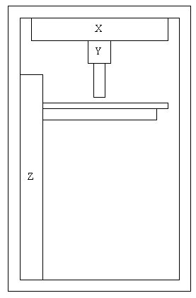
Arrangement of the Stages:
X will be mounted to the top of the cabinetry.
Y will be mounted to X.
Z will be mounted to the left side of the cabinetry
*As the build progresses, the Z stage and build platform will lower.
** The image below should give you an overall idea of the arrangement.
In all reality, I would like more than one extruder, but I believe I will already be pushing these actuators to their limits.Y will be mounted to X.
Z will be mounted to the left side of the cabinetry
*As the build progresses, the Z stage and build platform will lower.
** The image below should give you an overall idea of the arrangement.
Anyhow, this thread will be about 3D printers, filament extruders, electronics, and software. I will provide photos and video when possible. For those of you who are unfamiliar with me or my work, the following link should give you a little clue.
http://forums.parallax.com/showthread.php/129612-My-Current-Prop-Based-CNC-Photos
EDIT: I forgot to mention that the X and Y stages will be belt driven, and the Z stage will be screw driven.
Comments
Good to see you active here again.
Curious though, whatever happened with the sale of your spring invention. If I recall correctly, you had some sort of a deal pending ?
Sometimes /often?/ big business is hard to close.
Good luck with your new endeavor.
Cheers,
Peter (pjv)
The pending deal fell through because I got impatient and started throwing insults at them. Pretty much blew that opportunity because of my stupidity, impatienece, and temper. Since then it has been on the back burner, but I have been thinking about my next move with that project. Patience and a cool head have never been part of my virtues.
I am however looking forward to this new project and machine, and very eager to test my new design. IF the new design works, I should be able to create actuators quickly and inexpensively, and I believe they should be highly accurate. You never know until you try. My total cost for X, Y, and Z should be around $300, which is not a bad investment if they work. Of course it will take me a while to make the prototypes, but if they are worthy, I will be creating jigs, so that I may produce them rapidly for the 3D printer market.
My very first order of business is to order my parts and raw materials, and start building my own hot end and filament feeder. On second thought..... I think I should build an actuator prototype first, just to make sure the concept will work.
I had to do some running around, so while I was out, I picked up the following items:
(3) Feet of 1/4" brass rod
(1) #50 drill bit
*Cost $10.17
(3) Feet of 7/16" brass rod for making a combination heat sink and wire bobbin for 30 guage insulated Nichrome resistance wire
(3) Feet of 30 guage insulated Nichrome resistance wire
(1) 100K Thermistor
(Some)High temp epoxy
(1) Roll of 1/4" Kapton tape
I could just buy a ready made extruder and bolt it on, but I figure by having these materials, I can experiment with making different hot ends.
EDIT: Oh and the center of the acorn nut will be drilled with the #80 bit
EDIT: I just discovered that 1/8 NPT has an inner diameter close to 1/4", so the 7/16" brass rod mentioned above will be abandoned and replaced with a small section of 1/8" brass pipe (approximately 1/2" - 3/4" in length) for making the combination heat sink/wire bobbin. This pipe will be drilled with a letter D drill bit and the 1/4" brass rod will be driven into it for a press fit.
Also, don't worry about hostile exchanges on the interwebz. It's just a by product of not seeing one-another face to face.
Anyway, what CAD program will you use to draw your machine? Sketchup is great, unless you have access to Autocad.
In case you don't know, McMaster is an excellent source for all kinds of goodies. I'm probably 100 miles from their warehouse, but I get the parts the next day. Overnight delivery when you pay for regular shipping. 3PM order arrives at 10AM. You can't beat that with a gd stick!
Glad to hear that your machine is coming along and that you decided to go with steppers.
I have been using TurboCad ever since I began using a computer many moons ago. Since then, I have upgraded several times, and I will probably have to upgrade again to handle stl files for 3D printing. I am pretty good at it at this point in my life, from legal patent drawings to 3D reditions.
As for McMaster-Carr, well I order from them all the time and I will be placing a large order with them later tonight, as well as ordering other supplies from other vendors. I am also pretty close to McMaster (approximately 45 - 50 miles away). I have always wanted to visit their warehouse, but have not made the trip just yet. And I agree that their deliveries are outstanding. Most deliveries arrive the very next day after I order. If only my other orders arrived so quickly. Metal deliveries take forever.
** On a side note, my hot end project is coming along quite nicely, however I am altering my original plan. I now intend to make the cap nut as part of the heat sink. The hex portion of the cap nut will now be turned down to match the diameter of the 1/8 NPT pipe. So in other words, half of the heat sink will be the cap nut and the other half will be part of the 1/8 pipe.
I also like that everything is constant for the x & Y motions, and as the mass of the print increases, it only affects the Z, and the Z is very easy to contol, since it only builds down.
Some of the guys use fireplace ceramic for the hot end, is that what you are using? It was kind of expensive for a tiny little tub online. I found the same stuff (I think) at Menards for $5 for a pint.
You mean UHMWPE? Since you visited several years ago, everything has changed as far as my designs and planning goes. However I did build a very nice actuator which utilized UHMWPE, but it was highly affected by temperature due to the thermal expansion of the plastic. At one temperature it would work flawlessly, but at another it would bind, so I abandoned that that material for this purpose and redesigned my whole actuator concept.
As for x, y, and z, well I seen a similiar concept on another 3D printer and it seemed to me that that was the only way to fly, sweet and simple, or at least so I think.
The hot end was turning out quite nicely until I tapped the 1/8 tubing onto the assembly. At first glance, it appeared that it would be a perfect fit, but after tapping it onto the assembly, there was a couple extra thousands of clearance, perhaps there was a seam in the pipe that fooled me. So I am altering my plan and I will now be making nozzle/bobbin/heat sink assemblies from brass hex stock, however I will continue to use 1/4" brass bar stock to feed the nozzle. As for the high temp expoxy, I have not yet determined the exact material that I will use.
If you are interested, here is a drawing of the next hot end that I will attempt from hex bar. Notice the bore hole for the thermistor, and then check out the video.
EDIT: I forgot the link to the video http://www.youtube.com/watch?v=Y3CffV7VkOQ
I was going to suggest that the two of you meet up in person since you're both in the same part of the country, but it appears this already happened.
Ken Gracey
With my new design of linear actuators (providing they work), he might become #2 on the old totem pole
After looking at numerous extruder designs, I noticed that most of them include a fan and perhaps a heat sink over the stepper motor area, and some have two fans, with one being above the extruder. Just exactly what needs to be cooled and why?
Since most of the extruders I have seen were made of plastic, I am assuming the entire extruder assembly must be cooled due to heat transfer from the heated barrel or nozzel, which might warp or melt the plastic extruder itself.
In my particular situation, most of the extruder will be constructed from aluminum (with the exception of a PTFE heat isolater), so I wonder if I even need a fan for cooling. As described above, my nozzle and barrel will be made from brass, having a total approximate length of 1-3/4", and approximately 3/4" of barrel will extend into a 2" long piece of PTFE. The PTFE will be fastened to an aluminum motor mount. As I see it, only the PTFE could possibly require cooling, to keep it from melting or warping, and/or stop heat transfer from the PTFE to the aluminum motor mount. Plus I suppose that it might be necessary to prevent melting of the filament within the PTFE. Am I right or wrong in my assumptions?
Thanks in advance for any insight you may provide.
Bruce
I looked at extruders a couple years ago, here what I gathered from what I read:
* Heat transfere depends on the cross-sectional area between the hot part and the cold part.
* We want the hot part controled either "just above melt point" or just below melt point"
* we want to REST of the machine consistently at room temperature, because everything changes when tenperature changes.
This means that we havbe to calibrate whne the machine is hot, any calibrations when the machine is cold are just a ball park and will change once it heats up.
Now here the part tha answers your question:
THE TIP of the extruder must quickly change from below melt to above melt temp (180 F to 205 F for PLA). The REST of the extruder needs to be at room temperature, the heat flowing in from the hot end will affect the filament in the extrude, it can melt too soon. This can happen if we puase fro a bit. So, the fan is to cool the extruder tip AND the extruded plastic.
Note that the extruder is also cooled by the mass of the filament moving through it. If the filament stops moving, the heat pprilfe changes, and the print can be inconsistent.
The Fan keeps everything in better control, the heat is ON when the filament is moving, and turns off when its not, and doesn't precook the filament in the extruder tube.
Please check all this, I might not rememer correctly. .
The all aluminum might have the opposite affect, i that instead of cooling one place, the bigger affect is heating another place. You would do well to check with nophead and those guys that invented all this. But I recall something about the heat was counter-intuitive, probably because I know nothing about it. There are all metal extruders out there now, so don't base anything on my weak information.
This might be the critical thing.
The other thing is we need to ensure proper clamping force between the drive gear and the idler bearing, or the filament will just shred and not move. This was the biggest learning curve for me, using a modified Wade's extruder.
After writing my previous post, I did quite a bit more research and made some more of my own conclusions. Add that with the information that you have provided and I now have formulated a full theory of operation.
This is what I now believe:
Consider the illustration below.
I believe that you are correct and the happy place as illustrated would probably be around room temprature, or lets say somewhere around 70 degrees fahrenheit. To create an ideal and efficient hot end, I believe one would have to experiment with three thermistors, one at the hot end, one at the cold end, and the other where the transfers collide. By monitoring these three locations, a person could probably control the entire assembly very efficiently. However once you have an assembly all dialed in, the thermistor count could be decreased to just one at the nozzle. Or such is my belief.
I think you got it nailed. Here, this might take some time, but I believe it will be less time than building all the test rigs and running all the tests, and making all the worng guesses. Consider reading this:
http://hydraraptor.blogspot.com/
nophead and his pals did all the experiments, and took all the wrong turns, and worked it all out, over the course of several years. And they were expert to begin with. The contributors in the comments alos lead to other blogs etc; nophead is the easiest to remember. This answered every question I could think of (regarding RepRaps) and many I did not think of.
I think the early discussions of hot ends start in 2007 around the original DC extruder motor.
Drawback was he had to spend a lot of time following directions to put it together. I cant wait to be able to afford a 3d printer
You usually have a (ducted) fan cooling just below the tip of the hot end. The hot end should stay hot, and the cooling in an ideal world should happen only on the deposited/extruded filament.
You can use it, switch it off and in some printers modulate it.
With pla glass transition is quite sharp, so the fan is on all the time during printing to solidify the plastic as soon as deposited.
With abs the transition is not so sharp, moreover cooling too much the plastic could cause delamination.
So you print with no fan, little bit of fan or fan only when filling and not on the outer loops.
It depends on the filament, on hot end temperature, on printing speed and part geometry (a slender part where the printer comes back to the same spot will cause heat build up, so you need more cooling to avoid part curling. This is more critical with abs)
The fan on the top simply keeps the filament entering the hot end cool enough in order to soften only when it's supposed to do. If it softens too early you create a blob on the upper part, causing troubles or mayhem.
The most delicate part of a hot end is to have the heating element and the temperature sensor as close as possible and close to the tip.
This way you have little delay, hysteresis a good precision and predictable results.
In many cases a couple of degrees of difference in the extruder's temperature change dramatically the result.
Consider even with "professionally" assembled Hot ends using the same filament the printing temperature should be adapted a little bit to compensate a small displacement of the sensor, and consequently a delta between the temperature measured and the actual temperature of the extruded filament.
Massimo
@ whiteoxe
@ max72
As for cooling the filament as it leaves the extruder, I have done some reading on this subject, and it sounds as though some people have had success with this. Although I have not incorporated it into my design at this time, I would be wise to add support for such a cooling system, just in case I want to add it in the future. Some people mentioned an air pump for this purpose.
So for an advanced cooling system, I now believe there are three components:
- Fan for cooling the filament before it enters the extruder.
- Fan for cooling the cold end of the hot end.
- Air pump for cooling the filament after it leaves the hot end.
@ everyoneI received my order from McMaster-Carr several days ago which included most of my hardware and several miscellaneous tools, and today I received all my metal, drive gears, and belts for the X and Y axies. Over the course of the next several days, a few more orders will trickle in, and I still need to make a few more orders, but at this point, I definitely have enough parts to start my build. I just hope that my motors have a enough torque, because I certainly don't want to buy new motors for this design.
For those of you who build their own machines, I thought I would share a little design information pertaining to belt tensioning on the X and Y axises. I am sure that some of you already know this, some may already use this concept, and others may be seeking an answer to belt tensioning problems. My goal for designing this machine was to make it as cheap and accurate as possible. Belt tension is a very complicated subject or at least I think so, and better results for 3D printing will certainly be accomplished with an adequate belt tensioning system. I am not about to claim that this is the best belt tensioning system, but several people have claimed good results by using it, and in fact, during the salvage of an old HP scanner, I found the exact same tensioning system. Too make a short story short, I will be using the torsion springs shown below, which can be acquired here - http://www.ebay.com/itm/171258890153?ru=http%3A%2F%2Fwww.ebay.com%2Fsch%2Fi.html%3F_sacat%3D0%26_from%3DR40%26_nkw%3D171258890153%26_rdc%3D1#ht_236wt_1152
They're up the road from Parallax and I've watched their design go through a number of iterations to arrive at perfection.
Ken Gracey
Thanks for sharing. That is a very nice looking extruder! That is the first extruder that I actually like.
When I first started thinking about making this project, I figured I would just buy an extruder and bolt it on, but since I could not find one I liked, I started to design my own. I have a little experience in this area, since building the wire feeder for the spring bender CNC. This is not much different, except that it has hot end. After building that machine, I am much more aware loads, jams, etc..., so I must admit that I am not particularly fond of the idea of direct drive, and I am opting for a geared solution. The geared solution is quite a bit more bulky, with more weight, but I think a geared solution would be more dependable.
However if my design fails, I will be purchasing a printrbot extruder
Everyone always considers low cost, and many do buy low cost.. so and El Cheapo is right in the mix.
But what I am really wondering is how we can get a Propeller CNC solution that is better than what everyone is using on the Arduino UNO. This is the code side of the project that needs to get up to speed and I do believe it is quite possible.
The Propeller is ideal for controlling 3 or 4 stepper motor controllers in real time, and the CAD software for CNC has been around a long time, design files can be provided via SDcard.
It would be a shame to complete your project and not have a Propeller driving it all.
The CNC thread is in the Propeller forum and I just bumped it to the top. You can read all of it and the beginnings if you go there.
I would love to control this machine with a Propeller solution, but I am currently a one man problem solver. I am very bad at estimating times, but I estimate that it will take approximately a week to fabricate the core components of this 3D printer (prototype run), at which point, I will be seeking a serious solution to run it. However I will undoubtedly be prototyping with the Propeller and Gecko drives to test the actuators and other core components. Providing the core components work well, I will be open to all serious solutions to run it efficiently and accurately.
However I must readily admit that I am not particularly fond of the idea of using 3rd party software for the machines operation.
But on the software for the Propeller front, it seems that a complete 3-axis stepper motor package is a lot closer than I thought. Yes, there is a bug about precision; but the majority of the package is quite impressive. So I am reading through what it has and how to use it.
The software seems worthy of being completed. Or in the least, it covers far more ground that I could easily achieve independently, so it is worth being understood to allow for inclusion in whatever a final good result might me.
This software is NOT just about a 3-D printer, it could be used for other X, Y, Z devices == CNC milling machine or a CNC router.
You may want to go to OBEX and search for CNC and download the .zip file
Parallax did have a very active Propeller CNC solution for creating a CNC router to cut printed circuit boards. And that was low cost. Some were made of plywood and the accuracy with adequate.
Thanks for sharing. That was an interesting document. Someone mentioned this controller in another thread, and I believe earlier in this thread, but I had not looked at it yet. Once I get the core components assembled, I will take a look at it and most likely take it for a test drive.
Some days, I just wish I was born to become a machinist. They seem to have all the toys that we require these days. But having a hobby that requires a fork lift and a low-boy trailer to relocate your collection of toys and some rather hefty 3 phase power to drive your equipment just never allowed me to get into such.
Sometimes you just have to make do with what is available. For quite some time, I have been cutting my aluminum stock the old fashioned way.... MANUALLY.... I am getting way too old for that Smile
When my grandmother was still alive, she gave me my grandfathers old Craftsman band saw. Then we she passed away, my uncle claimed it was rightfully his and wanted it back. To avoid turmoil within the family, I surrendered the band saw without an argument, who in turn gave it to his son (my cousin), who in turn gave it to his son. Several years ago my uncle died, and then after a couple more years, my cousin made certain that I got the band saw back, and also threw in my grandfathers old Craftsman wood lathe, as well as a huge pile of files and chisels, for which I am thankful and grateful.
I have already modified the lathe for making lead screws for screw driven actuators, but as for the band saw, it has just sat there for quite some time. So todays project is to move the band saw from the garage and into the basement, attach a motor, select a blade, and calibrate the saw. I have not looked at the saw in a while, but I believe I should be able to cut all my parts with it, except for the tubing. This would really save me a lot of labor.
In addition to that, my best bud is lending me his combination disc/belt sander today. The addition of these two machines will be a welcome addition to my small arsenal. So today I will be busy trying to make my future days a little easier.
Yeah, I got a Bridgeport in my garage. It was a pain in the rear to move it around, costing a few hundred dollars just for that. There are some websites describing how people rig these bad boys, and that was very useful. If you get one, don't worry about 3 phase power too much. As long as you have 220 in your house for your dryer, you are good-to-go for a Bridgeport.
Method 1 for generating 3 phase power from single phase is crazy enough. You take a 3 phase motor and apply 220 single phase to it. You get it started literally pulling a lanyard, and then you can pull 3 phase off of it for your Bridgeport. This method sucks, but it does work. I did it this way.
Method 2 is golden. You buy a drive off of Ebay for about $250, and you're in like Flynn. Just make for sure you buy the right kind of electronic drive. (Single phase 220 AC to 3 phase 440). This is what I use on my setup right now.
And, I'm in agreement with all of you about Parallax CNC. It just has to be done. No matter what. You've got this excellent chip that might as well be designed for the purpose. And then you've got this 3D printing starting off in a big way right now, and so the market is open to anyone. Some of the popular stuff like Mach3 relies on a parallel port. That's pretty old fashioned. So, it's time for an update to USB, at the very least. I'm tinkering around with a Prop-based controller myself, but at this point it's just tinkering.
Yeah, I am not a big fan of parallel port control either. Hopefully, I will soon be taking a good look at the options available.
Referring to the drive for your bridgeport, how many amps will that handle at 440V?
Many thanks to Don Starkey for doing so much heavy lifting so that others can benefit.
The ONE big bug is that the circular output buffer seems to not be stable.
It may be how data is fed to it, or it may be the buffer's actual construction. Since it is dropping steps, it could be either one. The stack is set at 20 longs, it might be worthwhile to first increase stack space to see if the output buffer problem clears up. And another problem migth be the rate at which the output feeds to the stepper motor control may cause drop outs. This varies from controller to controller, so the rate of stepper output needs to be limited to a stable rate. I don't know if the code does or doesn't.
And then it seems that there is a real question of how to get this into a physical board. Parallax has a Propelelr Proto Board that might work, but there is a newer board that could be even better for this with USB port, and better space accomodation for an added ADC chip. The Parallax Propeller Project Board seems the right one for this. USB is more handy, and there is room for the SDcard interface with built-in pads.
http://www.parallax.com/product/32810
The original used optical sensors for limit switches, so it seems debouncing was not an issue. One might have to add some one-shot chips, such as the CD4047 to have the switches debounce before the Propeller as code space is a bit tight... well over 7000 longs already compiled.
This is a 3-axis CNC program. It would require further development for 4-axis.
++++++++++++++
Before everyone gets to wishing for more features, they should learn to use this code.
Also, there are a wide varitety of stepper motors that people wish to use. The actual stepper motor controller is very dependent on the stepper motors selected. So these should be considered separately. Pololu has a wide selection of stepper motor controllers for low power steppers which are feature rich (micro-stepping, power and voltage control, etc.). Ebay has the more powerful ones that are mainstream, about 3 amps and above NEMA24 devices.
What's the difference? MDI stands for Manual Data Input. GCode is essentially a compiled set of instructions for a XYZ control.
The Bad news...
The ArduinoUNO interprets GCode and that seems to pretty much the way that all 3-D printers have gone.
The Good news...
A Propeller GCode interpreter might be much easier to deploy from scratch.
So far I have not taken a look at it, but I most certainly will when I get X, Y, and Z constructed.
Going back to an earlier discussion, this sounds like a good starting point for Parallax to jump in if they wanted to branch off into the CNC market, because not only do you need the hardware, but you also need the software. Of course there are plenty of stepper drivers in the market, but a Propeller CNC controller sure would be nice. As you mentioned earlier, the Propeller can certainly handle step, direction, and enable/disable for the steppers, as well thermistors, a variety of switches, relays, etc.... And they already have the mouse, keyboard, and terminal all figured out, as well as other display options provided by other people. To me it sounds like all the goodies are already there, they just need to be organized and tweaked into a nice package. And of course, little circuit schematics for common stuff like limit and optical switches, and the like would also be helpful.
As I am sure you already, I have my opinions, but Parallax has made it this far without me
Well I just seen your MDI, take a look at this http://www.cnccookbook.com/CCCNCGCodeMDI.htm