

Supercap application question
 Don M
Posts: 1,654
Don M
Posts: 1,654
I have a project that I want to use a supercap on the 3.3VDC line with a Prop and SD card so when the Prop detects a power fault it allows enough power / time for the Prop to close the SD card file. I have proven the circuit just using a large value electrolytic so the logic and method behind all that works fine.
My question is do I want the supercap connected directly to the 3.3 VDC line just as a normal capacitor
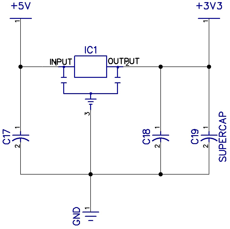
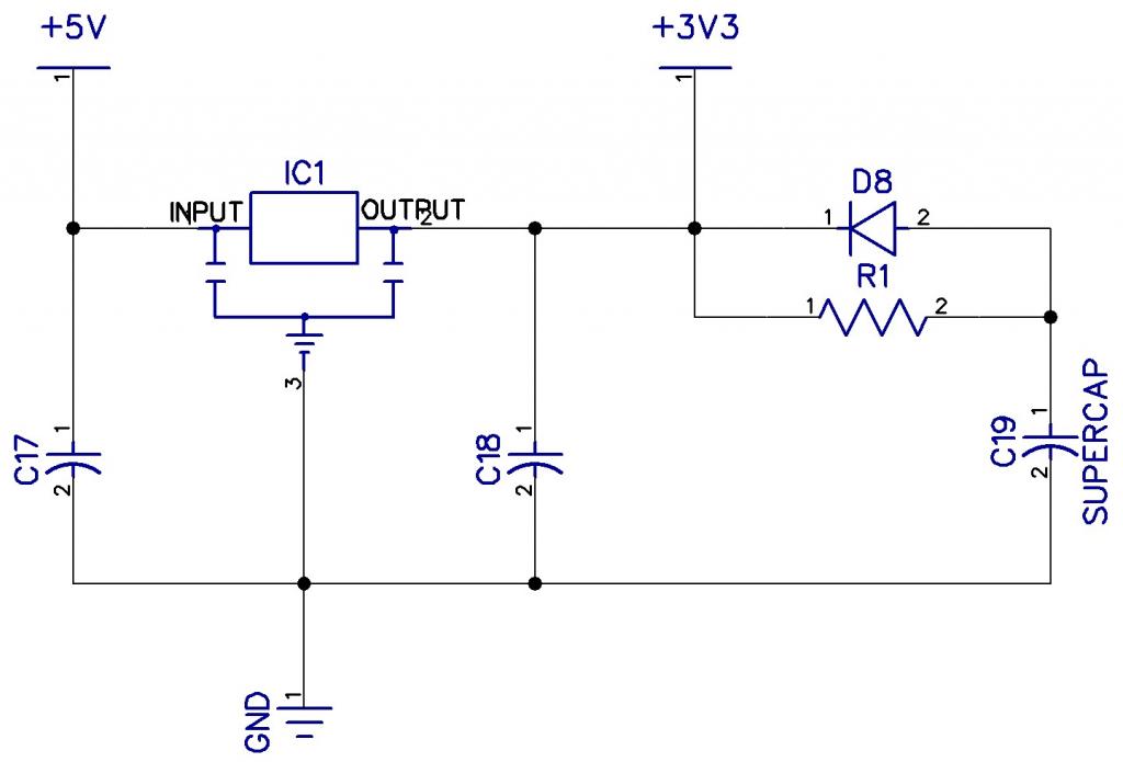
or do I want to isolate it via a low Vf schottky diode and then charge it via a resistor?
Back feeding the 3.3VDC regulator is not a problem so that isn't what I'm looking to isolate.
Just curious as I've never messed with these type caps before.
Thanks.
My question is do I want the supercap connected directly to the 3.3 VDC line just as a normal capacitor
or do I want to isolate it via a low Vf schottky diode and then charge it via a resistor?
Back feeding the 3.3VDC regulator is not a problem so that isn't what I'm looking to isolate.
Just curious as I've never messed with these type caps before.
Thanks.
Comments
Hal
Also, many voltage regulators require a protective diode when the capcitance on the output side is so large. Otherwise, a disconnect from supply and possible short circuit of the inputs will cause a huge backflow through the regulator. At least, the LM7805 will not survive such damage. Others might be better protected.
Two things you should keep in mind with supercaps:
The first (which was already mentioned) is that the series resistance of these super capacitors are very high. The ones I worked with were 30-ohm. No matter how much capacitance it has, a 30-ohm cap, charged to 3.3 volts will flatly not work with a draw of 20mA or more (due to the Propeller's 2.7V dropout). With a 1F cap, if you drop the draw by 2mA it will function for over 3 seconds. It is all about keeping the current draw low and consistent, so the power getting to the Propeller stays above the 2.7V rating.
If you do the exact same scenario, but charge the cap on the 5V rail, and regulate it down with a LDO regulator (one that looses 0.3V or less), you could operate all the way up to 50mA and the Propeller will still function for 10 or so seconds (somewhere around 66mA is the hard cut off for this scenario).
Adding a diode anywhere in the circuit and things just get worse for all scenarios.
The second is that for long term projects, if the capacitor is continually charged, there is a significant drop off in usable capacitance after a couple years of use. We ran into this potential problem with a project I was working on, and decided to go to a 9V battery for backup power.
Hal
Do you mean place a diode from the output (anode) of the regulator to the input (cathode) of the regulator?
So all this talk about series resistance with the caps. Something I've never taken into account before. I'm assuming Ohm's law is applicable here? Give me a math example maybe using your 20 mA example and what happens if maybe the load is 100 mA. At 3.3V.
Supercaps (double-layer electrolytic) don't normally go beyond 3V or so, 5.5V part is likely to be two in series I believe (although they keep coming out
with newer technologies). Putting the energy storage at the higher voltage is usually the best place - your circuitry may assume that the 3V3 rail isn't
active when the 5V rail is powered down.
You will need some sort of power-falling warning too.
An alternative is to use a smarter sort of regulator, like
http://www.microchip.com/wwwproducts/Devices.aspx?dDocName=en010593
this one is a Charge pump regulator, so keeps 3v3 on Vo as Vin falls from 5.5V to 2.1V
that range allows a smaller/cheaper storage cap.
It's all about Ohm's law. It's pretty simple:
V = I * R -- So 0.02A (20mA) * 30-ohms == 0.6V drop
A charge at 3.3V with a drop of 0.6V gets us to 2.7V (the dropout for the Propeller -- thus no function).
At 100mA:
0.1A * 30-ohms == 3.0V drop -- and not much can run at 0.3V.
In the opposite direction: 10mA:
0.01A * 30-ohm == 0.3V drop -- resulting in a 3.0V output (it will function).
So now we do the math to see how long it will last:
( V(in) - V(drop) - V(dropout) ) = functional voltage
and V(functional) / I * C(Farads) = active time in seconds
So (3.3V - 0.3V - 2.7V) == 0.3V is our functional voltage
0.3V / 0.01A * 1F == 30 seconds
This of course assumes a linear current draw as the voltage drops.
That's why increasing the charge voltage makes such a big difference. If the input goes from 3.3V to 5V, the functional voltage jumps to 2V, and now you could run the same system for over 3 minutes! Of course that doesn't account for the drop through a regulator, so it would be less than that, but you get the point.
EDIT: heck, if you charged the cap at 5V and put the buck-boost regulator on there that jmg mentioned, you could run for over 4 minutes!
Also, here is a whole list of ~1F 5.5V super caps, some of them even have 20-ohm resistance, so all those numbers above go up! http://www.digikey.com/scripts/dksearch/dksus.dll?FV=fff40002%2Cfff8000c&vendor=0&mnonly=0&newproducts=0&ptm=0&fid=0&quantity=0&PV13=1368&PV13=1315&PV13=1263&PV13=1277&PV13=331&PV13=339&PV13=1426&PV13=1085&PV14=730&PV14=30&stock=1&rohs=1
If this is true then how does Martin get away with this on his DNA board? Here is his schematic of the power supply. When powered by USB the +5V is fed through mosfet Q1 onto the +5V line essentially back feeding the 5 volt regulator. There is nothing mentioned on the data sheet for the regulators he is using. So what would be different about this back feeding the regulator with the USB versus a capacitor?
@Bobb Fwed-
Thanks for your lesson here. I received the supercaps today from Digikey. The .33F have an ESR of 200 ohms. (ouch) The 1F have an ESR of 20 ohms. So using one of Martins DNA boards I set up a program that logs to the SD card to measure the current draw @ 5V. It measured about 220mA. So using your calculations with the supercap on the 3.3V line means that even with the 1F cap @ 20 ohms I'd have a voltage drop over 3.3V (4.4 V) so in essence it shouldn't even run at all after disconnecting the power?
Correct.
What will happen is as soon as power is disconnected the voltage will drop too low, and everything will shut down. But then the current draw is low enough that the power will come back up to an operable voltage, but as things boot up the current will increase too much and you'll be stuck in a reboot loop until enough power has been lost from the cap.
EDIT: You would have to parallel 8 of them together to get the resistance low enough to operate. It would be down to 2.5 ESR, but then you would get 1.82 seconds of operation.
As I said in my first post, we ran into similar engineering conundrums, and ended up just popping a 9V battery on our device.
If you find a way to majorly reduce the power consumption of your project you could potentially work with supercaps, but as it is right now, it seems impractical.
So what I did on another board that worked was this-
24 - 40 VDC in >> switching regulator (LM2674-12V) that had 2 x 220uF >> 5 volt regulator >> 3.3 volt regulator. I monitored the 24 - 40 volt input through a voltage divider with zener and after it got down to less than 20 volts the voltage divider would toggle a pin on the prop telling it to finish and close files. I monitored (with a logic analyzer) the time it took to finish and write to the SD card and with the 2 x 220uF caps I had more than enough time. It was running with Martins DNA board and the caps on the 3.3 and 5 volt regulators are minimal. 3 x 100uf total.
So now I'm going to need to rethink this all a bit....
Even using the IC that jmg mentioned wouldn't work as the prop, eeprom, sd card, clock chip is what draws the 220mA and is over it's capability. Looks like my solution may just be large value caps on the input to the power supply and in between the 5 and 3.3 volt regulators....
Here is a clip from the TI data sheet for the LM317.
.
.
So I understand using something simple like a battery for backup. But I'm wondering how you "disconnected" the battery from the circuit after the processor was done doing it's thing? Otherwise whats not to keep the battery from just continuing to power the circuit?
You'd just have to keep in mind that Q2 would have to handle the load of the entire circuit. Also, the 9V would continually have a small load through R2, but R2 could be a pretty high value resistor. Again, look around for a better circuit (I'm sure there are some that don't put any load on the battery).
So much for the Supercap idea....
I may play with the battery / mosfet switch idea.
Thanks everyone for your ideas, thoughts and insights.
Don
That makes sense, as the Murata Module I'm guessing is a switching module, and there you gain from power conversion, and so you have serious dV available, and current will be lower than the 5V drain. (so you get close to 1/2*C*V^2 energy usage )
( 1 second is a lot of time to close a SD card)
That means you could reduce the secondary caps, and still be OK.
A little bit or surge protection would help on the IP side ?
Well, anything over about 10 mfd on the output side may cause a reverse current damage to the regulators if you don't include protective diodes.... though I am less sure you would have a problem with switching regulators. You really have to apply your real choice of regulators to super caps for any realistic comment on protection problems.
There are alternative solutions....
I discovered that while two linear regulators in parallel trying to achieve the same voltage are a known disaster; having one regulator provide 4.9 volts from a standby battery power and a wall wart regulator set to 5.0 volt will work to provide continuous uninterrupted power. This can even be done by adding one voltage regulator to an existing Propeller ProtoBoard. The trick is to separate the regulation enough to avoid having both trying to power at the same time AND to keep within the safe operating limits of the regulated devices.
Since most 5.0volt devices will tolerate up to 5.5 volts and much lower than 5.0 volts; a second power source at 4.9 volts is acceptable.
In such a scheme, the battery can even be a big Lead Acid cell with continuous trickle charge from the A/C mains. It just doesn't turn on the output until the other regulator drops below 5.0 volts (which is an off condition of the 5.0 regulator).
When the 4.9v regulator senses the presence of 5.0v on its output side, it remains dormant. The battery just sits in standby.
~~~~~~
While I found super-caps do provide a bit of power for a longer period than conventional caps, they really didn't perform long enough for me to be a good source for an 'uninterrupted power supply'.
And, they do add a lot of complications to conventional regulation goals.