@rogloh said:
Hey I just managed to use my capture code from a couple of weeks back to capture my video driver outputting RGB24 with NCO at sysclk/20 rate in active part of the scan line. Interestingly my TM decoder program barfed on the clock. Looks like the clock is not continuing to be output at the 5 high/5 low levels after this switchover. I think the individual bits are being doubled or something...strange transition from 10 to 16 to 20 bits for the clock (I will have to examine this further by getting my program to output more details than just skipping over the bad data).
Could you try a constant NCO freq of sysclk/20 so there's no switching, with the B+4 pattern?
@rogloh said:
I think that Verilog might be from Rev A, the channel command formats didn't quite line up as I expected, or I was misreading it.
This must be wrong. I don't think rev A had any in built DVI inside it, did it? Based on the dates of these older posts in 2018, it probably was discussion related to rev B changes. So the Verilog should be for rev B. Unfortunately my recall of P2 history is getting somewhat rusty these days. It's 6 years ago now.
@TonyB_ said:
@rogloh said:
Hey I just managed to use my capture code from a couple of weeks back to capture my video driver outputting RGB24 with NCO at sysclk/20 rate in active part of the scan line. Interestingly my TM decoder program barfed on the clock. Looks like the clock is not continuing to be output at the 5 high/5 low levels after this switchover. I think the individual bits are being doubled or something...strange transition from 10 to 16 to 20 bits for the clock (I will have to examine this further by getting my program to output more details than just skipping over the bad data).
Could you try a constant NCO freq of sysclk/20 so there's no switching, with the B+4 pattern?
I could try with DVI as the pattern is fixed during control periods and should work if I adjust sync timing a bit.
@TonyB_ Note that it is possible to capture locally using the streamer - you don't need to have the DVI board for this. Approach:
COG 1 sends channel commands to dummy DVI output pins. All 8 pins are setup in this mode with WRPIN so any read back will log actual output state of pin:
wrpin ##P_LOW_1K5|P_HIGH_1K5|P_SYNC_IO|P_OUTBIT_A , a
Use COG2 to stream the 8 pin bits back to HUB RAM for dumping pin pattern and data/clock bit analysis. Use a COGATN from COG1 to start COG2 to begin the capture, done at full clock speed (SETXFRQ ##$80000000)
xinit ##X_8P_1DAC8_WFBYTE|X_WRITE_ON| CAPTURE_LEN| (((DIGITAL_BASEPIN) >> 3)<<20),#0
Then scan through captured bytes and print 4 bits of each byte for positive DVI channel signals as strings of 1's and 0's framed by rising edge of clock bit.
This approach allows interactive messing with delays and channel command underrun positions when NCO values are changed to see if that has any effect.
@rogloh said:
One other thing I realized I could do if LUT space is at a premium is to separate the steps of the processing like you did, with CRC stuff first then TERC4 encode. The code for both steps could be read into the LUT at different times before being executed, then you don't need the full instruction space for all HDMI work to fit inside the COG simultaneously. That sort of more fine grained overlay approach should help allow us to keep the 256 entry palette mode with any luck. So the sacrifice might then be that this HDMI driver variant is crashable if its HUBRAM is corrupted. That's not ideal but it's still a reasonable tradeoff to make IMO as most other system code already works that way anyway. Even things like the mouse sprite code could work that way too, and free more COG RAM.
Is all of the debug region full? Could the overlays be tucked up there to try protecting them from most rampant code?
Debug region would depend on the application setup itself, but I guess it could be installed in there if that's a nice protected area.
@TonyB_ said:
Could you try a constant NCO freq of sysclk/20 so there's no switching, with the B+4 pattern?
Still bad. When the NCO is static and not at sysclk/10, but sysclk/20, I get 9 high clocks and 11 low clocks. I tried with immediate mode as well and it doesn't help. You just have to use sysclk/10 it seems.
This lines up with what is in the P2 documentation which states:
Digital video output mode requires that the P2 clock frequency be 10x the pixel rate. For 640x480 digital video, which has a pixel rate of 25MHz, the P2 chip must be clocked at 250MHz.
The NCO frequency must be set to 1/10 of the main clock using the value $0CCCCCCC+1, where the +1 forces initial NCO rollover on the 10th clock.
<blockquote class="UserQuote"><div class="QuoteAuthor"><a href="/profile/" rel="nofollow"></a> said:</div><div class="QuoteText"><p>I had to optimize the HDMI generator for faster timing, which added an extra clock cycle to its output. Two days spent down this rabbit hole, but I've got it thoroughly proven now.
The only thing left on my plate is updating the streamer to accommodate the scope modes.
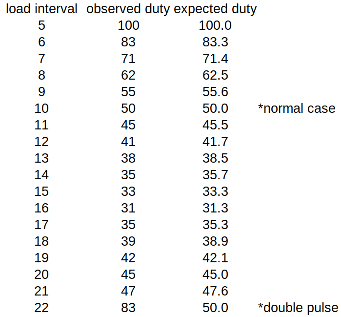
I'm going to guess that the cnt == 4'h9 was removed as part of the optimization. Instead of restarting after 10 bits, it naturally restarts after 16 bits when cnt rolls over. According to the verilog, the first 5 bits are 1. So for a pixel period of 10 clocks, the duty cycle is 50%. For a period of 16 clocks, the duty cycle is 5/16 or 31.25%. In the 17-21 bit range, the clock goes high after rolling over at 15. Then cnt is reset to zero at the next pixel load, keeping the clock high for longer. The biggest indicator of a problem is that at 1/20 pixel rate, the TMDS clock frequency is about half that of 1/10.
Thus the behavior of the DVI encoder is:
Restarts upon each new pixel and sends undefined bits after the 10 TMDS bits. Bad, but this is what we are assuming.
I didn't observe the data bits, but I assume those are undefined past 10 bits too. If the data bits were OK, then we could generate the 1/10 clock using smartpins. The phase doesn't matter. Sorry to waste everyone's time on this.
Yeah unfortunate outcome which we sort of thought would be the case, but it's good to prove it. I thought the same about the clock pin idea if the data was okay. I do see a nibble getting replicated at times but 6 other bits seem to be zeroes and the alignment is wrong.
@Wuerfel_21, I just tried your text video output code on my Plasma TV and I hear the tone. Very cool.
The cursor being that white "E" on row 4 instead of a solid block is only because you are keeping the cursor FG and BG colours as $1F. Make it $FF and it'd be solid white. Then you can select which scan lines to apply it to for block or underscore type. If you invalidate its co-ordinate at some rate like 2Hz in the driver you'll be able to get the cursor to start flashing as well. All that can come later.
if_c setbyte scantmp,#$1F,#1 ' select cursor color
@Wuerfel_21 In order to stream pre-encoded packets with TMDS control symbols in the data island that are already computed on the prior scan line I hope this streamer mode below results in streaming symbols data to the 8 bit DVI port if bit 1 of the long contains a 1 and the 32 bit data is interpreted literally as 3x10bit TDMS symbols in bits 31:2. I've never tried this out myself to date. If it doesn't work then it would require individual output immediates to the streamer instead which slows things down a lot and limits what else can be done in parallel which is the approach your driver currently needs to do. Have you ever tried this Ada? Is it known to work? Maybe my driver could be the first to use that approach if/when I add HDMI, not sure.
@TonyB_ said:
Could you try a constant NCO freq of sysclk/20 so there's no switching, with the B+4 pattern?
Still bad. When the NCO is static and not at sysclk/10, but sysclk/20, I get 9 high clocks and 11 low clocks. I tried with immediate mode as well and it doesn't help. You just have to use sysclk/10 it seems.
Thanks for the tests. Using XZERO instead of XCONT occurred to me last night, clutching at straws, but not worth trying now.
@SaucySoliton said:
@cgracey said:
I had to optimize the HDMI generator for faster timing, which added an extra clock cycle to its output. Two days spent down this rabbit hole, but I've got it thoroughly proven now.
The only thing left on my plate is updating the streamer to accommodate the scope modes.
@rogloh said:
@Wuerfel_21 In order to stream pre-encoded packets with TMDS control symbols in the data island that are already computed on the prior scan line I hope this streamer mode below results in streaming symbols data to the 8 bit DVI port if bit 1 of the long contains a 1 and the 32 bit data is interpreted literally as 3x10bit TDMS symbols in bits 31:2. I've never tried this out myself to date. If it doesn't work then it would require individual output immediates to the streamer instead which slows things down a lot and limits what else can be done in parallel which is the approach your driver currently needs to do. Have you ever tried this Ada? Is it known to work? Maybe my driver could be the first to use that approach if/when I add HDMI, not sure.
I don't think the P2 can stream TMDS encoded data from HUB. I can't seem to get it to work, tried both these and it won't output these pre-encoded patterns I read in from HUB storage. SETCMOD is $100 as well.
xcmd1   long    X_RFLONG_RGB24 | X_PINS_ON| ((DIGITAL_BASEPIN>>3)<<20)| 4
xcmd1    long    X_RFLONG_32P_4DAC8 | X_PINS_ON| ((DIGITAL_BASEPIN>>3)<<20)| 4

storage
long %1101001110_1100111001_0110001001_10
long %0001010110_1100111001_0001100101_10
long %0001010110_1100111001_0001100101_10
long %0001010110_1100111001_0001100101_10
That's weird, this 100% should work. I don't remember what my initial test code did, but it might have been just that. The RGB24 mode obviously will not work, it needs to be X_RFLONG_32P_4DAC8. Also check your pointer is actually pointing to the right thing.
@Wuerfel_21 said:
That's weird, this 100% should work. I don't remember what my initial test code did, but it might have been just that. The RGB24 mode obviously will not work, it needs to be X_RFLONG_32P_4DAC8. Also check your pointer is actually pointing to the right thing.
I hope it can be made to work. I will have to try it again and check everything.
Also this thread is getting real off-topic very quickly, @VonSzarvas can you use your thread-splitting powers? From about post #1970 onwards its just HDMI discussion unrelated to game emulation.
@Wuerfel_21 said:
Maybe post your code for scrutiny....
I got it working One part of my setup code got modified earlier today to create a blue gradient test pattern which basically trashed things and rewrote my pattern longs after startup but before they were read by the streamer. Fixed that and I'm all happy now. This means I should be able to stream TERC4 packets from HUB and do other work in parallel. With 640 P2 clocks occurring during 2 packet data islands in the horizontal blanking a mostly freed up COG could probably read in the 256 entry palette and even a lot of dynamic HDMI code during this time using block reads which allows more time in the active portion for executing the actual code. Nice.
Is all of the debug region full? Could the overlays be tucked up there to try protecting them from most rampant code?
Debug region would depend on the application setup itself, but I guess it could be installed in there if that's a nice protected area.
Was thinking more about this. Due to the way any (future) HDMI driver of mine would work, even if I could run chained/overlay snippets from the read-only DEBUG area, corruption of HUB would still trash the video output as I need HUB RAM to render dynamic HDMI data islands for streaming out on the next line. Trash those and it's probably goodbye to video sync (although they would get rewritten regularly so it might clean up by itself).
@pik33, what was the resolution you were able to obtain with your HDMI/DVI output? I'm trying to figure out the upper bound to be targeted by my driver. Something like 1024x576p wasn't it? That would make 128 character columns maximum for text. Might be about the limit (1152 x 600 x 50 Hz container framing = 345.6MHz P2). Would be nice if it reached 1024x600 as there are some LCD's at that size.
@rogloh said:
Ok doesn't look good - here's the TMDS data when it switches NCO rates. Look at the clock bits
Oh wow, something's really broken in there. 11/9 duty clock, how come? I guess it sources it from the NCO counter somewhere? In that verilog snippet the serializer had its own counter, why not use that?
So for a very theoretical P2 rev D, this should really be fixed in some way (+ add hardware TERC4 modulation - possibly as %xxxxxxxx_xxxxxxxx_RRRRGGGG_BBBB010x ?)
How about doing two chars at a time?
%RRRRrrrr_GGGGgggg_BBBBbbbb_xxxxx10x
rrrr/gggg/bbbb = CharN
RRRR/GGGG/BBBB = CharN+1
For audio TX, you essentially need 86 HBlank pixels, so ultra-reduced blanking is out of the question, anyways.
8 data preamble
2 leading data guard
2x32 actual data
2 trailing data guard
8 video preamble
2 video guard
In theory it should be possible to get away with only one packet per line (so 54 pixels) by skipping the sample packet when a clock packet is sent on that line, but empirical evidence suggests that wouldn't work properly due to sample jitter.
@TonyB_ said:
How about doing two chars at a time?
%RRRRrrrr_GGGGgggg_BBBBbbbb_xxxxx10x
rrrr/gggg/bbbb = CharN
RRRR/GGGG/BBBB = CharN+1
HDMI data island packets are rather horrible.
They are somewhat problematic yes, but if you can pre-process the packets first, store them in hub and can stream them out then at least you can do something else in the meantime. You do get at least 64 pixels worth of time during these two data packets and this is 640 P2 clocks which is quite a lot. Plus there are some more cycles in the back porch too and surrounding island guards etc. That's why I freaked out a little initially when I couldn't get the streaming from hub to work with literal TMDS data on my first attempt - but it does work thankfully. If it didn't work, I very much doubt I'd be able to fit HDMI in with my video driver model.
For my driver I plan to use this interval to read in the next region which can contain a new palette (up to 256 longs need to be read from HUB). With setq burst transfer that'll happen in around 320 clocks in the presence of 1/10 HUB transfer load from the streamer for the data island stuff (I did a test which showed approx 23% extra hub load). My next region handling code in my current driver takes in the vicinity of 130 clocks to process the next region data and update all the COG params etc. This is 450 clocks total with the slowest palette transfer (~45 pixels worth) so it will complete in time during a dual packet data island and leave cycles for other streamer channel commands to be prepared and a few other things that are handy to do at this time, perhaps the mouse sprite scan line work &/or PSRAM mailbox update but I'll need to check those too. A PSRAM read request can potentially be launched a little later during the active portion, though the mouse work needs to be done before the scan line is emitted. The earlier you launch the mailbox request and later you do the mouse once the data comes back the better it is for the sprite to work correctly for externally sourced frame buffers in PSRAM. For HUB RAM frame buffers it's fine to do the mouse after the pixel doubling is complete.
Some restrictions on horizontal timing will likely need to be put in place for this. My existing P2 video driver is quite flexible with the sync settings and as long as there is time in the code itself it'll allow quite reduced blanking. But with audio and other processing any HDMI driver variant will need a minimum amount of time during sync for it to even work which would then prevent very customized or heavily reduced blanking timings. This may not be an issue for any LCDs or other displays that can run at lower refresh than 60Hz, though I'm unsure of how that would affect audio until we try it.
@Wuerfel_21 said:
For audio TX, you essentially need 86 HBlank pixels, so ultra-reduced blanking is out of the question, anyways.
8 data preamble
2 leading data guard
2x32 actual data
2 trailing data guard
8 video preamble
2 video guard
In theory it should be possible to get away with only one packet per line (so 54 pixels) by skipping the sample packet when a clock packet is sent on that line, but empirical evidence suggests that wouldn't work properly due to sample jitter.
Yeah I'd always plan on sending two packets, then you can issue the clock regeneration packet at any time with an audio packet present as well. AVI infoframes can use this slot too once during vertical blanking even if audio is being sent (but just not on the lines with clk regen).
I was sort of thinking 1280 pixels would be a reasonable upper bound for text mode (160 columns of 8 pixel data). This limit lets me use the LUT RAM during text rendering as follows:
$00..$ff - 256 entry palette (for this scan line output)
$100-$10f - 16 entry text colours (for next line text colour processing)
$110-$14f - 64 entry font scan line data (256 bytes - one per character)
$150-$19f - 80 long entry (160 words of character colour + char data)
$1ff-$160 - 1280 pixels worth of colour nibbles output by text processor (or 160 longs), rendered in reverse pixel order (downwards) into LUT RAM which increases buffer use
Longs from $110 through $1ff could be used for HDMI code space for processing packets when text is done, and also for pixel doubling. Even mouse code could be run from there.
A few other tidbits - approximately this instruction space in COG RAM is currently used for the following parts. Some of these may be candidates to run from LUT if read in dynamically when required assuming sufficient clocks to read the code in time.
54 longs for region handling
63 longs for mouse sprite handling
30 longs for pixel doubling code space - ideally needs to run from COG to give all LUT buffer to pixel doubling
90 longs for text/cursor processing - won't fit in LUTRAM unless text columns are reduced accordingly.
64 COG longs for font data - but this could be reallocated to HDMI data/code space by moving to LUT and limiting character columns to 160 (from 240)
So potentially ~180 COG RAM longs may be freed for HDMI code/storage, plus 240 256 of LUT.
More HDMI state is needed to be put into COG RAM. I hope 240 256 LUT longs will be sufficient for most of the actual data packet processing stuff, excluding audio polling code and storage which has to run a few times per scan line to keep up with the input sample rate and as a result would need to be run from COG RAM.
EDIT: actually once text is done you get 256 longs free in LUT RAM, not 240, as those 16 longs from $100-$10f are only needed to be present during the text rendering work.
EDIT2: I noticed I do have another 16 longs free in LUT during text, so it think I could push it upto 1368 pixels or 171 columns - although 1360 is a better limit value for doubling being a multiple of 16. My plasma is 1366x768 panel IIRC


Comments
Could you try a constant NCO freq of sysclk/20 so there's no switching, with the B+4 pattern?
This must be wrong. I don't think rev A had any in built DVI inside it, did it? Based on the dates of these older posts in 2018, it probably was discussion related to rev B changes. So the Verilog should be for rev B. Unfortunately my recall of P2 history is getting somewhat rusty these days. It's 6 years ago now.
I could try with DVI as the pattern is fixed during control periods and should work if I adjust sync timing a bit.
Yes, TMDS encoder was a Rev B value-add, I think I remember that.
@TonyB_ Note that it is possible to capture locally using the streamer - you don't need to have the DVI board for this. Approach:
COG 1 sends channel commands to dummy DVI output pins. All 8 pins are setup in this mode with WRPIN so any read back will log actual output state of pin:
wrpin ##P_LOW_1K5|P_HIGH_1K5|P_SYNC_IO|P_OUTBIT_A , a
Use COG2 to stream the 8 pin bits back to HUB RAM for dumping pin pattern and data/clock bit analysis. Use a COGATN from COG1 to start COG2 to begin the capture, done at full clock speed (SETXFRQ ##$80000000)
xinit ##X_8P_1DAC8_WFBYTE|X_WRITE_ON| CAPTURE_LEN| (((DIGITAL_BASEPIN) >> 3)<<20),#0
Then scan through captured bytes and print 4 bits of each byte for positive DVI channel signals as strings of 1's and 0's framed by rising edge of clock bit.
This approach allows interactive messing with delays and channel command underrun positions when NCO values are changed to see if that has any effect.
Is all of the debug region full? Could the overlays be tucked up there to try protecting them from most rampant code?
Debug region would depend on the application setup itself, but I guess it could be installed in there if that's a nice protected area.
Still bad. When the NCO is static and not at sysclk/10, but sysclk/20, I get 9 high clocks and 11 low clocks. I tried with immediate mode as well and it doesn't help. You just have to use sysclk/10 it seems.
This lines up with what is in the P2 documentation which states:
https://forums.parallax.com/discussion/comment/1460410/#Comment_1460410
Verilog: https://forums.parallax.com/discussion/comment/1450144/#Comment_1450144
I'm going to guess that the cnt == 4'h9 was removed as part of the optimization. Instead of restarting after 10 bits, it naturally restarts after 16 bits when cnt rolls over. According to the verilog, the first 5 bits are 1. So for a pixel period of 10 clocks, the duty cycle is 50%. For a period of 16 clocks, the duty cycle is 5/16 or 31.25%. In the 17-21 bit range, the clock goes high after rolling over at 15. Then cnt is reset to zero at the next pixel load, keeping the clock high for longer. The biggest indicator of a problem is that at 1/20 pixel rate, the TMDS clock frequency is about half that of 1/10.
Thus the behavior of the DVI encoder is:
I didn't observe the data bits, but I assume those are undefined past 10 bits too. If the data bits were OK, then we could generate the 1/10 clock using smartpins. The phase doesn't matter. Sorry to waste everyone's time on this.
@SaucySoliton said:
Yeah unfortunate outcome which we sort of thought would be the case, but it's good to prove it. I thought the same about the clock pin idea if the data was okay. I do see a nibble getting replicated at times but 6 other bits seem to be zeroes and the alignment is wrong.
@Wuerfel_21, I just tried your text video output code on my Plasma TV and I hear the tone. Very cool.
The cursor being that white "E" on row 4 instead of a solid block is only because you are keeping the cursor FG and BG colours as $1F. Make it $FF and it'd be solid white. Then you can select which scan lines to apply it to for block or underscore type. If you invalidate its co-ordinate at some rate like 2Hz in the driver you'll be able to get the cursor to start flashing as well. All that can come later.
@Wuerfel_21 In order to stream pre-encoded packets with TMDS control symbols in the data island that are already computed on the prior scan line I hope this streamer mode below results in streaming symbols data to the 8 bit DVI port if bit 1 of the long contains a 1 and the 32 bit data is interpreted literally as 3x10bit TDMS symbols in bits 31:2. I've never tried this out myself to date. If it doesn't work then it would require individual output immediates to the streamer instead which slows things down a lot and limits what else can be done in parallel which is the approach your driver currently needs to do. Have you ever tried this Ada? Is it known to work? Maybe my driver could be the first to use that approach if/when I add HDMI, not sure.
1011 dddd eppp 0001 - RFLONG -> 32-pin + 4-DAC8 32 out %PONMLKJI_HGFEDCBA_ponmlkji_hgfedcbaThanks for the tests. Using XZERO instead of XCONT occurred to me last night, clutching at straws, but not worth trying now.
Impressive detective work. So the solution is a very minor change to the Verilog?
As a thought experiment, assuming Verilog modified, would all bpp settings support pixel repetition?
I don't think the P2 can stream TMDS encoded data from HUB. I can't seem to get it to work, tried both these and it won't output these pre-encoded patterns I read in from HUB storage. SETCMOD is $100 as well.
That's weird, this 100% should work. I don't remember what my initial test code did, but it might have been just that. The RGB24 mode obviously will not work, it needs to be X_RFLONG_32P_4DAC8. Also check your pointer is actually pointing to the right thing.
Yea, since the expansion from whatever you give the streamer to 32 bit color+control is done one layer up.
I hope it can be made to work. I will have to try it again and check everything.
Long time ago now but didn't Chip do this using rev A silicon?
No I don't think rev A could officially do TMDS encoding, however IIRC might have been Saucy who encoded a bit bang version that could do it.
Maybe post your code for scrutiny....
Also this thread is getting real off-topic very quickly, @VonSzarvas can you use your thread-splitting powers? From about post #1970 onwards its just HDMI discussion unrelated to game emulation.
Very funny given this is already a split thread
deleted
I got it working One part of my setup code got modified earlier today to create a blue gradient test pattern which basically trashed things and rewrote my pattern longs after startup but before they were read by the streamer. Fixed that and I'm all happy now. This means I should be able to stream TERC4 packets from HUB and do other work in parallel. With 640 P2 clocks occurring during 2 packet data islands in the horizontal blanking a mostly freed up COG could probably read in the 256 entry palette and even a lot of dynamic HDMI code during this time using block reads which allows more time in the active portion for executing the actual code. Nice.
Thread split
Was thinking more about this. Due to the way any (future) HDMI driver of mine would work, even if I could run chained/overlay snippets from the read-only DEBUG area, corruption of HUB would still trash the video output as I need HUB RAM to render dynamic HDMI data islands for streaming out on the next line. Trash those and it's probably goodbye to video sync (although they would get rewritten regularly so it might clean up by itself).
@pik33, what was the resolution you were able to obtain with your HDMI/DVI output? I'm trying to figure out the upper bound to be targeted by my driver. Something like 1024x576p wasn't it? That would make 128 character columns maximum for text. Might be about the limit (1152 x 600 x 50 Hz container framing = 345.6MHz P2). Would be nice if it reached 1024x600 as there are some LCD's at that size.
How about doing two chars at a time?
%RRRRrrrr_GGGGgggg_BBBBbbbb_xxxxx10x
rrrr/gggg/bbbb = CharN
RRRR/GGGG/BBBB = CharN+1
HDMI data island packets are rather horrible.
1024x600@50 Hz, at about 336 MHz. Timings are.... stretched way off specification, but work at every monitor I tried them
Edit: and yes, I moved from 576 to 600 because of these 1024x600 displays
For audio TX, you essentially need 86 HBlank pixels, so ultra-reduced blanking is out of the question, anyways.
In theory it should be possible to get away with only one packet per line (so 54 pixels) by skipping the sample packet when a clock packet is sent on that line, but empirical evidence suggests that wouldn't work properly due to sample jitter.
That would be more complicated for no gain, really. With my scheme, you could just use the 2x16 bit mode to pack two symbols into one long.
Yes.
They are somewhat problematic yes, but if you can pre-process the packets first, store them in hub and can stream them out then at least you can do something else in the meantime. You do get at least 64 pixels worth of time during these two data packets and this is 640 P2 clocks which is quite a lot. Plus there are some more cycles in the back porch too and surrounding island guards etc. That's why I freaked out a little initially when I couldn't get the streaming from hub to work with literal TMDS data on my first attempt - but it does work thankfully. If it didn't work, I very much doubt I'd be able to fit HDMI in with my video driver model.
For my driver I plan to use this interval to read in the next region which can contain a new palette (up to 256 longs need to be read from HUB). With setq burst transfer that'll happen in around 320 clocks in the presence of 1/10 HUB transfer load from the streamer for the data island stuff (I did a test which showed approx 23% extra hub load). My next region handling code in my current driver takes in the vicinity of 130 clocks to process the next region data and update all the COG params etc. This is 450 clocks total with the slowest palette transfer (~45 pixels worth) so it will complete in time during a dual packet data island and leave cycles for other streamer channel commands to be prepared and a few other things that are handy to do at this time, perhaps the mouse sprite scan line work &/or PSRAM mailbox update but I'll need to check those too. A PSRAM read request can potentially be launched a little later during the active portion, though the mouse work needs to be done before the scan line is emitted. The earlier you launch the mailbox request and later you do the mouse once the data comes back the better it is for the sprite to work correctly for externally sourced frame buffers in PSRAM. For HUB RAM frame buffers it's fine to do the mouse after the pixel doubling is complete.
Some restrictions on horizontal timing will likely need to be put in place for this. My existing P2 video driver is quite flexible with the sync settings and as long as there is time in the code itself it'll allow quite reduced blanking. But with audio and other processing any HDMI driver variant will need a minimum amount of time during sync for it to even work which would then prevent very customized or heavily reduced blanking timings. This may not be an issue for any LCDs or other displays that can run at lower refresh than 60Hz, though I'm unsure of how that would affect audio until we try it.
Yeah I'd always plan on sending two packets, then you can issue the clock regeneration packet at any time with an audio packet present as well. AVI infoframes can use this slot too once during vertical blanking even if audio is being sent (but just not on the lines with clk regen).
I was sort of thinking 1280 pixels would be a reasonable upper bound for text mode (160 columns of 8 pixel data). This limit lets me use the LUT RAM during text rendering as follows:
Longs from $110 through $1ff could be used for HDMI code space for processing packets when text is done, and also for pixel doubling. Even mouse code could be run from there.
A few other tidbits - approximately this instruction space in COG RAM is currently used for the following parts. Some of these may be candidates to run from LUT if read in dynamically when required assuming sufficient clocks to read the code in time.
So potentially ~180 COG RAM longs may be freed for HDMI code/storage, plus 240 256 of LUT.
More HDMI state is needed to be put into COG RAM. I hope 240 256 LUT longs will be sufficient for most of the actual data packet processing stuff, excluding audio polling code and storage which has to run a few times per scan line to keep up with the input sample rate and as a result would need to be run from COG RAM.
EDIT: actually once text is done you get 256 longs free in LUT RAM, not 240, as those 16 longs from $100-$10f are only needed to be present during the text rendering work.
EDIT2: I noticed I do have another 16 longs free in LUT during text, so it think I could push it upto 1368 pixels or 171 columns - although 1360 is a better limit value for doubling being a multiple of 16. My plasma is 1366x768 panel IIRC
Thanks pik33.