In a previous test I discovered that the Parallax USB serial client breakout board can be fitted to P56-P63 headers on the P2-EVAL (rev B tested) and doesn't interfere with the serial port for downloads and console use. The LEDs on this breakout board are then attached to P62,P63 and P56,P57. So long as you don't access the on-board flash (either keep it's CS high via the pullup or disable it fully via DIP switch) and you don't install an SD card then P58,P59 should be free to use for a USB client port (lower of the pair on the breakout). For this reason I've also added the header to my Octopus board.
This means that with the Octopus pin configuration I could fit a USB-host on P24-P31 (using upper nibble) a VGA/AV breakout on P32-39 which remains fully open (this could be used for monitoring incoming captured video+audio on HDMI), and a USB-client on P56-P63 headers. PSRAM and HDMI capture and regular serial IO would still operate under this scenario. Alternatively I could fit a 4 bit SD reader board on P32-P39 instead of video (for capture storage/playback) and have a video signal being output from P24-P31. Using VGA instead of HDMI output would allow high resolution video like 720p/1080 to be previewed during capture and/or played back from SD card as it doesn't incur the 10:1 sysclk:pixelclock ratio restriction that DVI signalling has.
Here's some of the top layer with the change I made where extra breakout boards can now be placed. I've also set it up it so you can disable the PSRAM clock from going to this 2x6 header (you need to solder a pad link to bring it out), as I didn't want a tiny radio stub antenna on the pin in case it might start creating reflections/ringing etc and mess up the PSRAM. I've also got a jumper header with a solder link below that can be cut to disable PSRAM in case it's not needed.
I did also bring out P24 to a breakout header which is the async pixel clock and it can drive an extra LED if needed on the USB host breakout or can provide 5 total pins if a custom VGA or YUV+LR output board is used here. As the async clock will only reach about 30MHz I'm less worried about RF stuff vs 160MHz for the PSRAM clock so didn't mind connecting to this pin but I did decide to place its connecting trace on the top layer just outside of the 2x6 header footprint in case it needs to be cut for any reason.
Boards are currently in the air today for arrival in Melbourne this week according to shipping status so I should know soon if they work.
Picked up the boards today. Sent off Friday morning and arrived in MEL Tuesday arvo all the way from China, pretty fast service.
Fits on the P2-EVAL thankfully, so I got the dimensions correct at least and the pogo pin hole is sitting above the XIN signal. They didn't seem to route out the small slot on the micro USB connector footprint as shown in the prior post above. It might have been too small for them but they seem to have skipped this or maybe I had it on the wrong layer, no matter I can probably cut the legs down on the connector a bit and still solder to something, or try to drill out the hole a bit bigger. There's still some SMD pad below too for solder attachment.
I'll probably have a go at soldering it up tomorrow when the lighting is a bit better. Not worth starting now in the evening. Not really looking forward to the FFC connector.
@VonSzarvas said:
If nothing else, that's a glorious dark blue mask !
Yeah it's striking. Not a perfect colour match but very, very close this time. I think Lachlan mentioned the soldermask colour can slightly vary from batch to batch at this fab.
This full stack should look quite good when together. Just missing the nice ENIG finish you guys use but what can you expect for 50c/board. LOL.
I was thinking this octopus frame grabber really needs all 8 of it's legs to be true to its name, it's not a heptapus/septapus. Now that I added in those pass through connectors on P24-P31 and P56-P63 I could do the same for P32-P39 which gives its eighth leg back. Once I respin with any fixes and if there's clearance I'll probably try to do it - however the corner mounting hole may get in the way, we will see. The other way to go is to use those 2x6 connectors that pass through longer male pins from the female sockets below the board though they can be messy to hand solder from above as solder wants to wick itself up the pin and it looks a bit out of place too. I think I'd pick a nicer/larger ZIF FPC socket as this particular one I ordered is positively tiny and tricky to use as well.
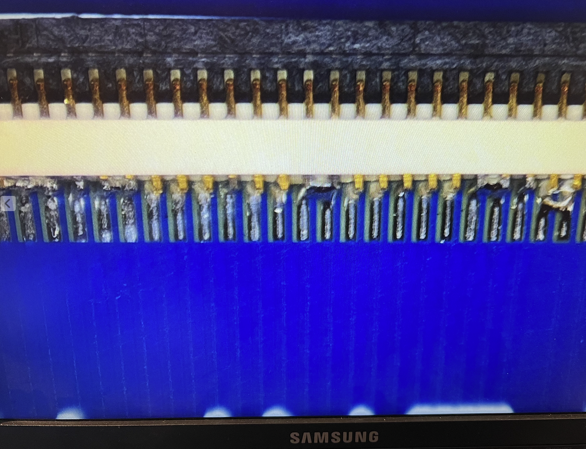
Result after hotplate cooking before cleanup work. Bridging doesn't look too hard to fix. Can't really be helped without use of a proper stencil this time around and just hand placement onto blotches of solder paste. I can't tell how well the micro USB went, but if it's shorted underneatch I can rework with hot air. FPC connector looks very slightly angled but I think the contacts are aligned sufficiently to work, time will tell.
EDIT: Nope under the microscope the FPC is off. Will have to rework that for sure. Also D+/D- are shorted together.
Uggh. Video microscope shows up all the imperfections. Wish I had this over the hotplate so I could see what it was doing. I will have to use the hot air gun to fix this mess.
UPDATE: Fixed the alignment, isn't flux wonderful stuff! Hope the ZIF connector still works, it got pretty hot during rework.
Board done for testing later tonight. Prep for stacking...
Fully stacked! It fits.
Wasn't a lot of fun doing this but I believe it's ready for testing. I fixed the USB connector and buzzed out all P2 signal connections to end of flat flex and no shorts between adjacent pins. Also buzzed through to USB-A end of USB cable.
@Tubular said:
Yeah I find it amazing those FPC connectors can do their job, so long vs wide/thick.
Yeah some are better than others. This FPC part from Mouser I selected for this PCB (far too quickly) has only 0.3mm of pin protruding out from the edge making soldering it a royal PITA. It's really too small for non-PnP setups. I didn't realize until it arrived just how tiny it was.
Looks great all stacked up like that. Good luck with the testing
Thanks, I'll need some luck for the high speed performance - hopefully all the ground related signal integrity issues I might have hit before like ground bounce during pixel switching is reduced now.
So at the least, I'll have another working PSRAM board for the P2-EVAL using my board, as all 4 chips are functioning. Here's the PSRAM test results from my board. Looks like it tested clean up to 350 MHz in my delay test program so it should work out ok at ~338MHz for NeoYume etc.
UPDATE: USB client port is working, mounting a drive on my Mac with Chris Gadd's USB client code. Looks like I fixed the solder short.


Comments
In a previous test I discovered that the Parallax USB serial client breakout board can be fitted to P56-P63 headers on the P2-EVAL (rev B tested) and doesn't interfere with the serial port for downloads and console use. The LEDs on this breakout board are then attached to P62,P63 and P56,P57. So long as you don't access the on-board flash (either keep it's CS high via the pullup or disable it fully via DIP switch) and you don't install an SD card then P58,P59 should be free to use for a USB client port (lower of the pair on the breakout). For this reason I've also added the header to my Octopus board.
This means that with the Octopus pin configuration I could fit a USB-host on P24-P31 (using upper nibble) a VGA/AV breakout on P32-39 which remains fully open (this could be used for monitoring incoming captured video+audio on HDMI), and a USB-client on P56-P63 headers. PSRAM and HDMI capture and regular serial IO would still operate under this scenario. Alternatively I could fit a 4 bit SD reader board on P32-P39 instead of video (for capture storage/playback) and have a video signal being output from P24-P31. Using VGA instead of HDMI output would allow high resolution video like 720p/1080 to be previewed during capture and/or played back from SD card as it doesn't incur the 10:1 sysclk:pixelclock ratio restriction that DVI signalling has.
Here's some of the top layer with the change I made where extra breakout boards can now be placed. I've also set it up it so you can disable the PSRAM clock from going to this 2x6 header (you need to solder a pad link to bring it out), as I didn't want a tiny radio stub antenna on the pin in case it might start creating reflections/ringing etc and mess up the PSRAM. I've also got a jumper header with a solder link below that can be cut to disable PSRAM in case it's not needed.
I did also bring out P24 to a breakout header which is the async pixel clock and it can drive an extra LED if needed on the USB host breakout or can provide 5 total pins if a custom VGA or YUV+LR output board is used here. As the async clock will only reach about 30MHz I'm less worried about RF stuff vs 160MHz for the PSRAM clock so didn't mind connecting to this pin but I did decide to place its connecting trace on the top layer just outside of the 2x6 header footprint in case it needs to be cut for any reason.
Boards are currently in the air today for arrival in Melbourne this week according to shipping status so I should know soon if they work.
Picked up the boards today. Sent off Friday morning and arrived in MEL Tuesday arvo all the way from China, pretty fast service.
Fits on the P2-EVAL thankfully, so I got the dimensions correct at least and the pogo pin hole is sitting above the XIN signal. They didn't seem to route out the small slot on the micro USB connector footprint as shown in the prior post above. It might have been too small for them but they seem to have skipped this or maybe I had it on the wrong layer, no matter I can probably cut the legs down on the connector a bit and still solder to something, or try to drill out the hole a bit bigger. There's still some SMD pad below too for solder attachment.
I'll probably have a go at soldering it up tomorrow when the lighting is a bit better. Not worth starting now in the evening. Not really looking forward to the FFC connector.
If nothing else, that's a glorious dark blue mask !
FPC... yeah... less solder, more flux, you'll be grand !
Yeah it's striking. Not a perfect colour match but very, very close this time. I think Lachlan mentioned the soldermask colour can slightly vary from batch to batch at this fab.

This full stack should look quite good when together. Just missing the nice ENIG finish you guys use but what can you expect for 50c/board. LOL.
I was thinking this octopus frame grabber really needs all 8 of it's legs to be true to its name, it's not a heptapus/septapus. Now that I added in those pass through connectors on P24-P31 and P56-P63 I could do the same for P32-P39 which gives its eighth leg back. Once I respin with any fixes and if there's clearance I'll probably try to do it - however the corner mounting hole may get in the way, we will see. The other way to go is to use those 2x6 connectors that pass through longer male pins from the female sockets below the board though they can be messy to hand solder from above as solder wants to wick itself up the pin and it looks a bit out of place too. I think I'd pick a nicer/larger ZIF FPC socket as this particular one I ordered is positively tiny and tricky to use as well.
Result after hotplate cooking before cleanup work. Bridging doesn't look too hard to fix. Can't really be helped without use of a proper stencil this time around and just hand placement onto blotches of solder paste. I can't tell how well the micro USB went, but if it's shorted underneatch I can rework with hot air. FPC connector looks very slightly angled but I think the contacts are aligned sufficiently to work, time will tell.
EDIT: Nope under the microscope the FPC is off. Will have to rework that for sure. Also D+/D- are shorted together.
Uggh. Video microscope shows up all the imperfections. Wish I had this over the hotplate so I could see what it was doing. I will have to use the hot air gun to fix this mess.
UPDATE: Fixed the alignment, isn't flux wonderful stuff! Hope the ZIF connector still works, it got pretty hot during rework.
Board done for testing later tonight. Prep for stacking...


Fully stacked! It fits.
Wasn't a lot of fun doing this but I believe it's ready for testing. I fixed the USB connector and buzzed out all P2 signal connections to end of flat flex and no shorts between adjacent pins. Also buzzed through to USB-A end of USB cable.
Yeah I find it amazing those FPC connectors can do their job, so long vs wide/thick.
Looks great all stacked up like that. Good luck with the testing
Yeah some are better than others. This FPC part from Mouser I selected for this PCB (far too quickly) has only 0.3mm of pin protruding out from the edge making soldering it a royal PITA. It's really too small for non-PnP setups. I didn't realize until it arrived just how tiny it was.
https://au.mouser.com/datasheet/2/185/FH33J_40S_0_5SH_10__CL0580_1330_0_10_2DDrawing_000-1615193.pdf
Thanks, I'll need some luck for the high speed performance - hopefully all the ground related signal integrity issues I might have hit before like ground bounce during pixel switching is reduced now.
So at the least, I'll have another working PSRAM board for the P2-EVAL using my board, as all 4 chips are functioning. Here's the PSRAM test results from my board. Looks like it tested clean up to 350 MHz in my delay test program so it should work out ok at ~338MHz for NeoYume etc.
UPDATE: USB client port is working, mounting a drive on my Mac with Chris Gadd's USB client code. Looks like I fixed the solder short.
Here here! Great job @rogloh
And guess you now know you have good a quality FPC... with the material being able to withstand a healthy blast of airgun set for lead free temps!