

P2-Stamp pre-launch samples
 knivd
Posts: 104
knivd
Posts: 104
The P2-Stamp chip-module as previously discussed here: https://forums.parallax.com/discussion/174317/new-p2-module#latest
...and on Github: https://github.com/knivd/P2-STAMP
I want to give away a small number free samples to P2 programming wizards for more in-depth test on the hardware capabilities of the module, with the only request to feed me back with information about bugs/problems (or successful runs) to help potential future reivisions of the hardware. I will supply the module together with a bare PCB of the breakout board to make it easier to start with.
If someone is interested, please do let me know.
Thanks
Comments
I'm very interested. Postage to New Zealand might be a pain though. Maybe send a couple to Australia and Roger can pass one to me.
Posting to NZ shouldn't be too much of a problem. It is a very small thing.
Please DM me details
I would very much like to try a P2 stamp. I will PM address if a go.
Jim
Yes, of course
Interested")
Okay, you know what to do")
I'm of course always interested in freeloading, though if you give me a bare breakout board, it's probably above the procrastination threshold to acquire the parts and do the SMD soldering, so I guess I have to miss out.
May be the same problem for me, but as I am working at the technical unversity, I have an access to a workshop with a microscope and other stuff that makes SMD soldering easier, including a friend who has a lot of experience doing this.
These P2-Stamps are small and compact and we still have several robotics projecs at the university. We use Edges for this purpose now, but I can imagine a case when smaller form factor may be more useful.
PM sent.
😂🤣😂🤣 You funny
Craig
I’ve been lurking for quite some time and I don’t think I deserve a free module but I’m interested in buying one when they become available. It looks fantastic! Nice job!
As of 6 July, unfortunately at this moment I have no more left after the ones already requested. Sorry
Thanks for the kindness of donations.
Same for me, will happily buy when they're ready.
Cheers
Soldered up a PLCC socket on the breakout board that @knivd kindly sent me and installed the P2-Stamp module. The P2 is responding to a PropPlug download of a random LCD emulator project I have so this board is at least talking over serial. Still to test its peripherals including the on-board HyperRAM but hope to continue with that in the next days.
Power clips look a tad hairy. What voltage?
For now 5V input. Yeah looks worse in pic than in real life as there is some pin header insulation below it and a gap between pins so if it swivelled it still wouldn't short, though I will dig up another better clip like the red lead uses to be safer. Ideally I'd use the micro USB for power but don't have the right socket at this time. Could possibly solder some flying leads too instead.
Might aswell post my escapades. It sure runs NeoYume, but we already knew that. Except that I couldn't get the onboard SD socket to work properly at all. Too much resistor owie oof.
Video is actually really noisy, may be down to haphazard wiring though.
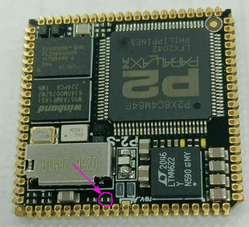
@Wuerfel_21 what's the issue with the resistor and SD? I see the P2 stamp schematic shows 300 ohms serial resistor on P58. P2 eval has 240 ohms. Not too much difference. Is this the resistor you are talking about?
That one, yes. Not sure if it's really the problem, but I will blame it, anyways.
I see, will take a look tomorrow hopefully. One thing I noticed which isn't ideal is this from the flash data sheet for S25FL256SAGB
Maybe that is somehow interfering with the SD...?
My external SD is connected to the same pins, so I don't think that's it? idk.
Yeah ok. Actually that part was the flash on the rev A P2-Stamp (which I have). A Rev C board uses a different flash part from ISSI according to its schematic (IS25LP256D) and that has no mention of that issue with the CS toggle without a clock signal. I understand that knivd sent a mix of boards out.
Not a big surprise that 300 vs 240 ohms is a fail. The SD driver timing in Flexspin is tuned to push the Eval Board, anything worse will be over the cliff.
That CS low concern is talking about post-programming only. EEPROM only gets programmed rarely.
PS: I didn't have any immediate plans to hook my Stamp up just yet. Need a PLCC socket I guess ...
Well, the resistor is accessible if we're all up for a collective change of value.
The stamp itself looks really beautiful!") I think the original idea was to enable custom application PCBs without the need for SMT assembly.
I think the original idea was to enable custom application PCBs without the need for SMT assembly.
The breakoutboard OTOH ruins this elegance a bit, especially when it comes without P2-EVAL compatible accessory headers. Du-pont wires are not good for fast signals...
Yeah, looks like soldering on a parallel resistor shouldn't be too tricky if the right tools aren't at hand to replace it.
If we do determine we need to change this resistor, then luckily it's on the top surface of the module as there is still some room to get an fine iron tip in there once installed in the PLCC socket. I'd be hesitant to try to remove the module from the socket once it is fitted. Seems like it could cause some board damage at the corners getting it out. It is a tight fit in the socket.
As I understand, it was just made as a quick test breakout board not intended a final eval board/product. Any "motherboard" as such would be up to the user of this module to design for their application, unless someone wanted to design another eval board around it and make that available to others.
Using the PLCC socket with only 0.1 inch pitch it would make it simple enough to route a compact two layer board containing this module. The P2 Edge is nice and compact as well but its connector is bulkier and takes up quite a bit of room.
Wow, the HyperRAM performance on this P2-Stamp board is nice. It runs all the way up to 350MHz at room temps (which is where I stopped my test). The input delays required seem to be less than the Parallax HyperRAM/HyperFlash board so any timing profile would need adjustment for this board to try to center the sampling time within the range of acceptable delays and these results are more consistent with no real frequency band dropouts like we used to see on the Parallax module. The fact this is V2 HyperRAM and rated up to 200MHz DDR as well probably doesn't hurt either.
I just needed to patch the HyperRAM latency to use 7 clocks insted of 6 for V1 HyperRAM. I'll try to make some changes to the code to better accomodate this. Also the delay test program's HyperRAM initialization API was designed around the original Parallax board that had a different pin mapping to this P2-Stamp board. There is another initialization API that can be used to customize the pin mapping.
Test results are zipped and attached.
Actually I stand corrected about the 350MHz performance. The above results were done at sysclk/2 transfer rates. The results for sysclk/1 are attached below and the performance tails off around 328MHz. @Wuerfel_21 are you achieving sysclk/1 rates for NeoYume or doing sysclk/2 transfers? NeoYume runs just around 336MHz doesn't it?
I do wonder what the performance would be without the test board wiring attached to the same pins as the HyperRAM data.