

fluid level sensor for melting pot
 ManAtWork
Posts: 2,368
ManAtWork
Posts: 2,368
As I already mentioned I'm currrently trying to build a soldering machine. Heating and temperature control are already solved. Next problem is how to control the level of the molten tin to assure constant flow from the pump to the nozzle.
Some machines have a float switch and simply feed tin wire to the pot until the switch signals "level reached". This is the simplest solution but tin wire is relatively expensive. I have a box full of tin bars with approx. 1cm squared cross section. I think I'll cut them in pieces with sheet metal scissors and manually drop some "pellets" into the pot after each soldering run.
To monitor the tin consumption in real time it would be good to measure the level continously instead of having only a single binary switch signal. Of course, the tin is hot (250°C) and the surface is covered with slag/dross which makes the task somewhat difficult.
Some ideas:
- put the whole pot on a scale. Problem: Cables and tubes to the hot unit cause drag and may lead to false weight readings.
- supersonic ping sensor to measure the distance of the surface to the top cover. Problem: even though the sensor is not immersed in the tin it get's fairly hot. A piezo transmitter without any plastic parts could probably withstand this.
- stick a PTFE tube or glass pipe into the pot and apply low gas flow to it so that bubbles come out of the bottom of the tube. The gas pressure is proportional to the fluid level. Problem: it must be inert gas otherwise it will cause oxidation and more slag.
- let a heat resistant but lightweight object float on the surface and connect it to a bowden wire. A standard non-heat resistant position sensor (capacitive, inductive or low-drag potentiometer) could be conected to the other side of the bowden cable.
The ping sensor is my favorite because it doesn't have any moving or immersed parts which can wear out or get dirty. Does anybody know a piezo transmitter that can be stripped to remove all heat sensitive parts? The ceramic disk alone should survive 250°C.
Any other ideas? The Goertzel demo board could probably also be made heat resistant if the FR4 PCB is replaced with ceramic substrate. But liquid tin dissolves almost all metals especially copper.
Comments
What's the cover made from ?
Is it transparent (heat resistant glass) ?
If it was then maybe something like this part VL53L5CXV0GC/1 from ST could be the possible solution ?
Just an idea, as you already know, how to measure these high temperatures:
Measure the heat flow via temperature difference of some kind of "cooler". The input heat flow of this "cooler" from the bath shall be proportional to the area (height), that is touched by the fluid.
:-) Christof
The cover is currently made from 2mm stainless steel sheet. But I can easily cut a hole and put a glass window in it. Time-of-flight optical sensor with 8x8 zones? Wow, that's overkill, but seems to be affordable. I hope it's not too complecated to read via software. I only need a single zone in the center. What resolution does it have? I can't find a data sheet at Digikey. The distance is around 100mm and 1mm resolution and repeatability would be OK.
Ok, I've found a data sheet of the VL53L3CX. It says +/- 10mm accuracy. Still amazing for a price of $6 and a range of 10mm to 4m. But I need better resolution.
@"Christof Eb." Good idea, but the surface is covered with a lot of dross (tin oxide, tin nitride and all sort of dust that has a lower density than tin). Non-metallic dirt has a much lower thermal conductivity than metal. So by measuring heat flow you would mainly measure the degree of dirt contamination instead of the actual surface level. This might also be useful to display when it's time to clean the machine but not not good for the original purpose.")
There are some similar time of flight sensors that cover a shorter range, I remember testing one with a 10 or 20cm range, I thought it was vl6180 but that appears to have a 60cm range.
These ToF sensors don't give the same result every time but (in my/our experience) you need to fit a gaussian curve to the distribution of multiple samples to get a central value. But you can take ~50 samples a second, so provided your levels aren't bouncing around too much perhaps this is an option for you.
Constructing a sensor using goertzel (ultrasonic, capacitive, inductive) would also be an option, and I think would work well, but hours of work. I'd try the vcsel ToF sensors first
Well a ping sensor would be easy, I thought. I just don't want to buy 10 different types to find out which one is easiest to modify to be heat resistant. As they are used in many of the Parallax robots I thought that someone here could give me advice.
ToF.... resolution is not the problem. I think it can be improved by averaging. But how about long term stability? If you switch the machine on the next day it should give the same results as the day before without re-calibration.
Perhaps the shape of the part in contact with tin could be a cone, small diameter submerged.
Shape like that (I don't know the use of that part.):
https://www.conrad.de/de/p/vigor-universaladapter-konus-v1963-25-vigor-v1963-25-2134241.html
====
This markup drives me crazy
Other idea: If it is possible to let something float, you could measure travel of the floating piece at a distant location, where it is not so hot.
Not sure if you’ve seen a commercial wave soldering machine. We had one at our assembly plant. It was 40ft long with the bath in the middle. The entry and exit tunnel was fed with nitrogen. We had a huge nitrogen tank outside. The solder was literally a wave of solder that rolled. I’m not sure what caused the wave to roll tho.
Is this what you’re trying to achieve?
Given the difference of density between the molten solder and fused quartz (or fused silica) solid parts, I believe you can use then to make a floater, like Christof Eb. did mentioned above, soldered to a lever, made from a rod of the same material, and use that fixture as a balancing movement multiplier, in order to amplify the movements of the floater.
Then the amount of displacement at the oposing end can be measured with great precision, and almost any interference from the hot solder pot.
There should be plenty of Oxyhydrogen welding services available near your location.
What about making floating probes of different shape (cone, rod) hanging on a balance. The balance is hanging fixed over the pot. So the floating probes dip into the tin, then the balance is nulled. If the tin level changes, the balance will incline to one direction or another. Sensor could be a photo sensor
The following "low-tech" sensor could be built relatively easy:

The 3 coils make a differential transformer. Coild A and C could be driven with same frequency but differnt phase. The phase of the B signal can be measured relative to A and C. This should be relatively exact and independant of amplitude and inductor value.
I don't have much space above the pot cover because the PCB to be soldered moves around an inch or so above it. So the sensor doesn't have to be inside the pot but relatively close. But the coils can be wound with glass fiber insulated wire.
But it's still a lot of work to develop and test a custom made sensor. If one exists I can buy and use with only little modifications I'd prefer that.
If you see it this way, a inductive sensor should do the job if the coil dips into the tin, its like shortening the coil. Will the pot be controled by a Propeller?
No, it's much smaller. I plan to make a selective soldering machine similar to the one Parallax has.
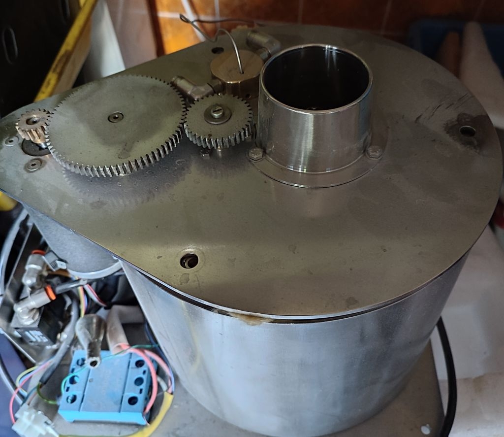

A motor (outside the pot, of course) drives a shaft protuding into the tin with a centrifugal pump. It pushs the liquid tin up a pipe to the nozzle at the top. There it forms a "fountain" of liquid tin. It pours only sime mm in height and diameter, enough to soak a single or double row of solder pads, for eample of a 0.1" pin header. The fountain is moved by a 3-axis CNC controller relative to the PCBs with the bottom copper layer facing the nozzle.
All parts that come in contact with the tin except for the nozzle are made from titanium which is one of the few metals that don't dissolve in tin. The "turbo" wheel of the pump is made from zirconium ceramics.
You are NOT recycling a sodium cooled fast breeder, aren‘t you?
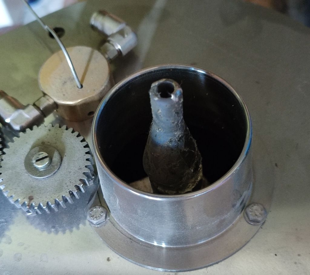
Forget it, no way. The liquid tin itself pours like water, only much heavier. But the slag is slushy and sticks to everything (see picture of the pump). During the soldering process the pot is flooded with nitrogen. But gas from bottles is expensive so the flow is only provided while actually soldering, not during heat up, standby and cool down. So some slag can't be totally avoided.
No, but a friend got cheap titanium from wrecked USSR airfraft turbines. He said he checked it with a Geiger counter. If Russians sell you something for cheap you have to be careful.
Do you really need to know the exact level of the solder, or just whether it's too low and needs more? If the latter, an aluminum rod (that the solder won't plate out on), inserted from above to the critical level of the solder, will short to the container if the level is high enough; not conduct, otherwise. By adding a second rod at a slightly different level, you can obtain hysteresis. IOW, if the level goes below the bottom rod, add solder until it reaches the upper rod. The difference in heights between the two rods will be your hysteresis band.
-Phil
That would probably work but we'd need 3 titanium rods. Aluminium dissolves in tin and actually poisons the tin. The pot is enamel coated and thus isolated. OK, we could use the pump and the riser pipe as 3rd electrode.
Knowing the exact level is not really neccessary but would allow for nice features. The falling level caused by tin consumption could be compensated in real time by speeding up the motor a bit so that the fountain height is kept constant and we had to re-fill less often.
There are two different levels for a low tin level alarm. One with the pump running and riser pipe filled and one at standby with empty pipe. If the alarm happens during the soldering process it has to be stopped. So it would be good to foresee that. Of course we can also choose a smaller hysteresis which means having to re-fill more often. Or just take a bigger pot which doesn't run empty so fast.
Hi
The VL6180X tof sensor ranges up to about 150mm, isn't too particular about reflectivity, I2C...
It will need to be shielded from the heat. The data sheet hints it will work through a transparent medium.
Dave
Tin conducts, so why not use a simple switch that uses a tungsten TIG electrode as one contact and the liquid tin as the other?")
Edit: My bad. PhiPi posted essentially the same idea.
Edit2: Using a single contact, if the surface of the tin is constantly in motion (ie, wavelets or ripples), you could ascertain the level to a pretty fine degree by looking at the duty cycle of the contact. The higher the level goes, the shorter the "off" time. The lower the level goes, the longer the "off" time. When the "off" time hits zero, the tin is completely off the contact. If the ripples are small (ie, 1 mm or so) and uniformish, you should be able to control the level to a very fine degree (sub-millimeter).
Purhaps it will be better to weigh how much solder is left in the pot, using a simple load-cell?
I have been working with piezoelectric hydrophones for many years, i have got several ultrasound transducers where all parts is ceramic and aluminium. These are quite expensive as they are high power units for long distance measurements. A cheap ultrasound transducer is buying one of those on Ebay sold as sparepart for a small ultrasound cleaner. I think there could be a issue with center frequency drifting off if they are heated to 250C degrees this will reduce sensitivity when receiving echoes dramatically.
What you describe is almost exactly a LVDT. Theyre kind of expensive because of their precision, but goertzel should shine when coupled with them.
You could mount a prism/mirror so the sensor can be placed off to one side to avoid the heat chimney effects ?
Google also find this comment on https://engineering.stackexchange.com/
A sensor that I've found works well is the Sharp GP2Y0E02B (digital version) (newer version is the GP2Y0E03). Configuring it as an I2C sensor, using an Arduino, I've been able to get sub-millimeter resolution (0.156 mm - Range is ~630 mm, with 12 bit resolution).
Almost didn't believe it when I read the spec, so I put the sensor on a Bridgeport with a test target, and used this as 'ground truth'. Out to 50 mm on a simple test, the error was less than 0.2 mm; out at 100 mm, I got about a 0.4 mm error.
No mention of how that varies over temperature, which may be one issue you need to manage.
Another less direct volume measurement could be to use the temperature sensor you already have and the precise induction control you already have, to capture the rate of change per kW, as that will give you the thermal mass the induction coil 'sees'. The good part of that approach, is no new sensors are needed, it is just software drilling down to check the rate of temp change per kW.
You just need two coils to measure the inductance. Use one coil as a reference that is always in a "fixed" proximity to the liquid metal, and the other as the sensor to the actual level of the liquid metal as it changes level.
Then the value becomes radiometric and will track with ambient temperature changes.
Reference: (See post #15 below)
https://www.electro-tech-online.com/threads/how-can-i-implement-force-sensors-into-my-project.161853/#post-1406495
That's also an interesting idea. It would surely work if we had a closed system. But as soon as the pump is running there is heat transfer to the outside air, the inert gas flow and the PCB. Gas flow is constant and could be taken into account in the calculations. But the thermal capacity of the PCB and it's components can vary a lot and is unknown to the machine. A well pre-heated PCB with only tiny parts on it would absorb much less heat than one with big and heavy connectors.
Yet another idea: I could measure the resonant frequency of the hollow space above the tin. This also depends on temperature and the composition of the gas (air vs. nitrogen) inside the pot but that should be relatively constant. If I connect a pipe of 1/2" diameter and 4" length to the pot and a speaker to the end it should stay cool. And the cold gas in the pipe should not have much influence on the resonant frequence.
Due to the lower frequency that would be a hum sensor instead of a ping sensor.")
I took a quick look at the data sheet. It specifies +/-10mm accuracy for the measured distance. But as it uses a digital image sensor and the triangulation method instead of time-of-flight I think it should be much less prone to environmental condition changes and drift. So hopefully repeatability and resolution should be much better than the 10mm tolerance which is also confirmed by your experiments.
Yes, I actually found some here. They look expensive but if they suited my needs I'd consider buying one. Unfortunatelly they are rated for only 150°C max.
So we have a lot of good ideas, now. I think I'll try the "classical" Goertzel sensor first, I mean the capacitive one. It can be made from standard PCB material alone as the Goertzel demo board from Parallax, only 1-dimensional. I know, standard FR4 is not meant for continous operation at 250°C but it can withstand it at least for some time otherwise it wouldn't survive soldering. So I can do some experiments with FR4 and if it works I can order ceramic or teflon based material later. PCB material is great because it can be used not only for the sensor itself but also for the connection rod and the floater.
And the best argument for choosing a Goertzel sensor is: it's one of the "bonus features" unique to the P2, it's fun and educational.
What about capacitance? Put a plate above the pot, and measure capacitance to ground to get distance from the top of the tin to the plate. That can be done entirely with one p2 smartpin in Schmitt inverted feedback mode.