The melting pot should be closed more or less to avoid oxigen coming in. So what about having a cone as a cover (inverted hopper) and as the tin reaches the tube of the hopper, every little change in volume results in a large change in tin level.
You might get enough thermal profile by looking at the side of the pot with a thermal camera ?
The part full with solder will be quite even, and then the sides will cool down above that, perhaps with enough change to then predict the fill level point with a curve-fit ?
As a quick-and-dirty solution, braze two 1 inch copper pipe caps together to make a float. Braze an arm onto the float. Braze a fulcrum/pivot on the container. Cantilever the arm over the edge of the melting pot to a switch/position sensor.
The copper and brazing rod has a melting point much higher than the tin, and once the copper gets coated with molten tin it shouldn't react much at all. I'm not suggestin this as a permanent solution, but it's a good "two adult beverages and an hour puttering in the workshop" project.
@evanh said:
By the sounds of it, both the copper and the brazing will dissolve (without melting) into the tin.
Based on my own (limited) experience, I doubted your answer and started googling a bit. Yup! Bigger than day, Evan was right. This paper really was an eyeopener:
What does seem to work exceedingly well is grey iron, an believe it or not, hollow grey iron spheres are cheap and plentiful and used for decorations in ornamental fencing.
So yeah… ixnay on the copper float idea for any long-term use.
@Circuitsoft said:
What about capacitance? Put a plate above the pot, and measure capacitance to ground to get distance from the top of the tin to the plate. That can be done entirely with one p2 smartpin in Schmitt inverted feedback mode.
The capacitance of a parallel plate coapacitor is proportional to the area and inverse proportional to the distance if (and only if) the area is large compared to the distance. This condition is difficult to achive unless one would make a ring electrode around the riser pipe. Furthermore a single parameter is always sensitive to unwanted side effects like temperature, dirt, wear or whatever. I don't say it's impossible but it would require much effort for calibration and linearization.
So when building a accurate sensor it's always a good idea to design it in a way that the output signal is the difference of two values that change in the same direction with the unwanted effects and in opposite direction with the parameter to be measured. This way the errors are balanced out and the result depends only on the "real" signal.
The dissolution problem can be totally avoided by making the float out of a non-metallic material. Teflon (PTFE) or PEEK are good candidates. Teflon is available in blocks as (citchen) cutting boards. For prototypes FR4 and epoxy could also be used but they probably won't last very long as the glass fiber layers tend to de-laminate when exposed to 250°C for a longer time. Even glass or clay may be used. However, as the whole assembly requires cleaning from time to time and the tin expands and shrinks a lot when heating up and cooling down I'd prefer a less brittle material.
To pickup the capacitor idea... The proposal with the differential transformer in post #13 can also be built with a differential capacitor instead:
If the connections to the propeller pins are short one of the two sides would be sufficient like on the Goertzel demo board. However I'd use differential (inverted/non-inverted) signals so that the capacitance of the cables have less influence. The final output signal depends on the capacitance ratio of A-B vs. B-C (and A-B inverted vs. B-C inverted) only like in a wheatstone bridge. The absolute values of the individual caps don't matter. This should make the sensor less sensitive to mechanical tolerances (horizontal play, dielectric wear), temperature change, dirt and so on.
I also thought about using a lever+fulcrum or rack+pinion mechanism to drive a rotary encoder but this is all to complicated if simpler solutions exist with purely linear movement.
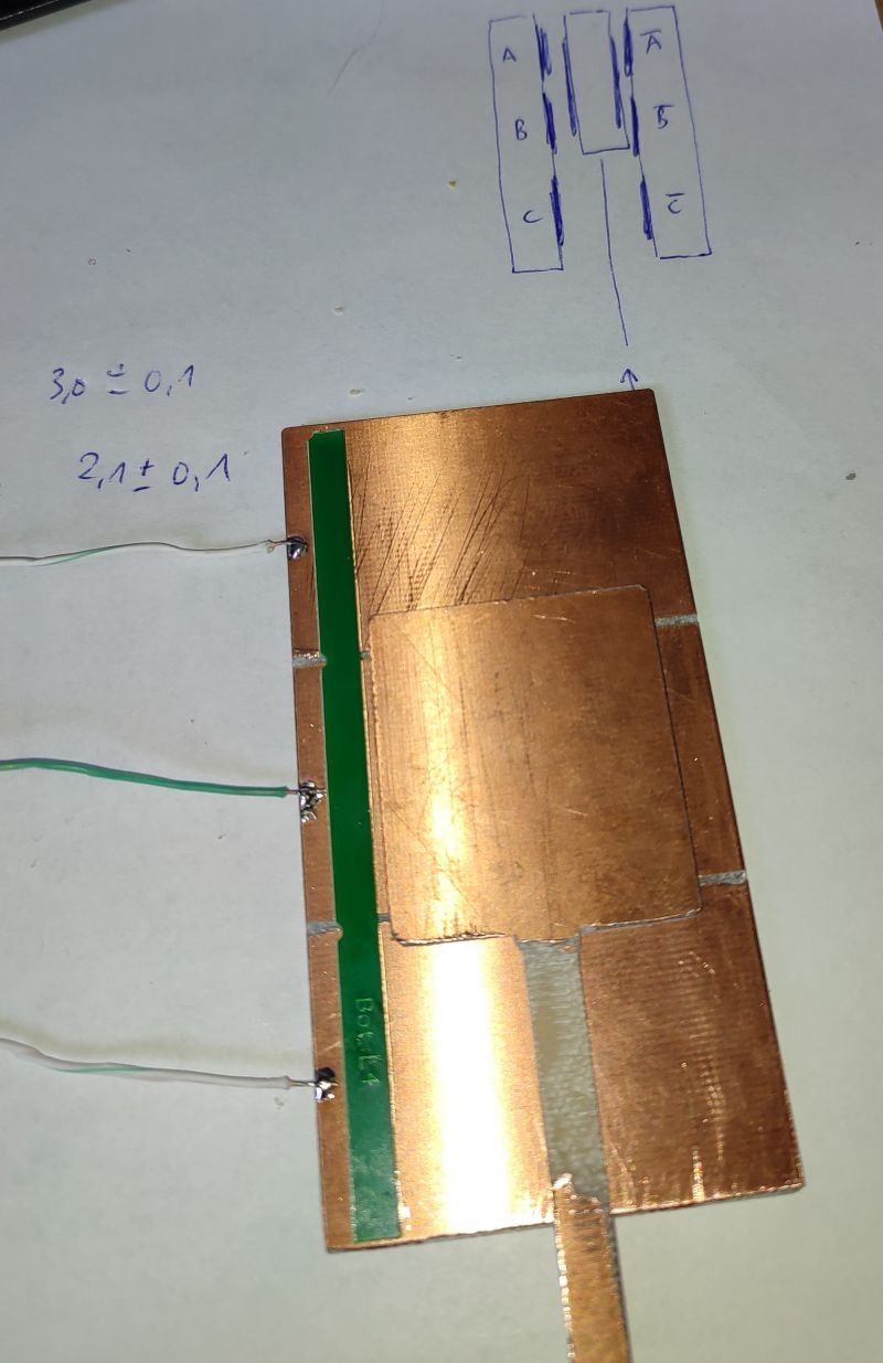
The capacitor plates can be made out of standard FR4 PCB material with the copper layer as electrodes and the solder mask as dielectric.
When I was working in the high-vacuum metallization (evaporation/sputtering) with different materials (aluminum/copper/gold/silver/magnesium/silicon/cadmium/...) on the roll-coaters (a machine that applied a thin layer of aluminum, thickness measured in angstrom's, over a 10km roll of plastic film or paper (used eg for paper capacitors/the aluminated paper in cigarette boxes/in food industry like plastic bag of chipster/....) using a high-vacuum chamber for the process, the thickness of the deposition was controlled:
on plastic translucent film with the optical principle (how much light is shelded by the thickness of the aluminum layer
on paper (not-translucent) with the RF, having aluminated paper running between the transmitter and receiver, and measuring how much the aluminum is shielding the RF field
Over a roll width of eg 1.5m there was ten/twelve sources of evaporation made of an silicon "boat" kept between two copper bars delivering the power. The boat is essentially a shaped diode which, when heated, melts the 1mm aluminum wire feed to it with a stepper motor. Care must be taken to not make the aluminum bath to big otherwise it creates a short between the copper bars routing the power through the aluminum bath instead of the silicon "boat" and thus loosing the temperature with the consequence of solidifying the bath.
The power applied on the boat at the end made the thickness on the film. So both, the motor speed and the power on the boat was controlled from the RF feedback. And every source, along the width of the roll had its own closed-loop control working very precisely. A 10km roll was metalized in about 4h IIRC (including the high-vacuum 10e-4mbar pump-time).
@ManAtWork so perhaps your idea of glass or pfte pipe inside the liquid bath can be elaborated in using an RF antenna inside the pipe and an receiver one under the cover and measure how much the liquid Sn is attenuating the RF signal.
An other option, since the liquid Sn is conductive at 250° and its conductivity up to 900° is also very stable in time, may be the measurement of capacitance between two electrodes of which one is isolated from the bath and the other is the bath itself
If you're willing to look in the RF direction, you could dip a wire (gray iron bar?) in the pot, connected to an RF signal generator and power meter. The lowest frequency that gives you a peak in your power reading will be a λ/4 stub.
Plenty of options here. What i'd do would be to go for the simplest and cheapest feasible solution.
I think going with the capacitive sensing idea seems like the good candidate to start with or the Time-of-Flight ranging sensor, whichever suits best.
The topic starts drifting toward the famous "barometer question" and the answers of Nils Bohr. We could also release drops of water at the top of the vessel and measure the time until we hear the explosions.
While there are some really good ideas I simply can't test them all. This is only one of the challanges of building this soldering machines. I start with the one with the highest "chance of success" vs. cost ratio.
@ManAtWork said:
To pickup the capacitor idea... The proposal with the differential transformer in post #13 can also be built with a differential capacitor instead:
Yes, if you drive that Sin and Cos, a passive coupling plate will sweep the pickup plate phase angle as it moves.
Or, you could make a Triangle wave Pin oscillator using the plate-C and then check the ratio of the frequencies - that's more like a touch sensor.
Thanks, Phil. This is great! Not that the eddy current inductive sensor is something I didn't know. But a change of perspective is sometimes really inspiring!
We could do it the other way round. Instead of measuring the tin level and adjust the pump motor speed accordingly to get the same fountain height at the nozzle we could simply move the nozzle below a simple standard sensor like an optical barrier or a proximity sensor. Then spin the pump up with increasing speed until the fountain reaches the desired level. We can then use the required speed of the motor to reversely calculate the tin level. That not only allows compensation of the tin level but we also find out if the pump, pipe or nozzle is clobbered and requires cleaning. And we totally get rid of the need to place anything into the pot where the conditions are not good for electronics or precision mechanics.
I wonder why I haven't noticed this possibility earlier. Sometimes we set our focus to the wrong detail of the overall problem.
A disadvantage of the nozzle vs. reservoir tin level measurement is that it needs extra time and interruption of the soldering process. But if we do it twice, once before and once after soldering a board the tin consumption can be recorded and extrapolated so that we can predict the required intervals for checking the level and re-fill.
I'll try to finish the Goertzel sensor as an exercise, anyway.
Yes, interesting. If we had a limited and boring standard microprocessor I wouldn't mind spending $3+ for an external converter (or $100+ for the eval board which is at least available, right now, the bare chip isn't). But come on, we have the Propeller2. I think it can do almost everything the LDC1000 can do. It can measure inductance, resonant frequency, Q factor all in software.
@ManAtWork said:
...If we had a limited and boring standard microprocessor I wouldn't mind spending $3+ for an external converter (or $100+ for the eval board which is at least available, right now, the bare chip isn't). But come on, we have the Propeller2. I think it can do almost everything the LDC1000 can do. It can measure inductance, resonant frequency, Q factor all in software.
Spot on !
The added bonus is that you only do it once in software and then can reproduce the functionality at almost no cost. Not to mention the easy path to enhance this functionality. Contrary to what you can achieve with separate hardware, that costs money with every single piece. And not only that.
That would be great to implement the eddy current LCR sensing on the Prop2, a nice demo of its capabilities. I'm interested in how you would go about it. The Prop2 could maybe even do multiple channels, like some of the application specific HID chips that TI now offers in the LDC lineup.
I'm still happily stuck with the Prop 1, which simply does not have that capability without external support. I did buy into the original LDC1000 and EVM board when it first came out, my goal being toroidal water conductivity measurement. The EVM board was a great help for proof of concept.
By the way, the bare chip LDC1101 is in stock at several distributers. (But then you have to contend with the 3mm, 10-pin VSON package!). The original LDC1000 is listed as obsolete.
I have to practice a little more with the Goertzel analyzer. I took my first exercise, the capacitive position sensor from post #45 is working. It is fairly linear in the range where the moving plate overlaps all three electrodes of the stator plate. I just had to adjust the gain and the scope range a little bit.
One more no-moving-parts idea. Wrap a few turns of wire around one end of an old ferrite loopstick core. Dip the other end in the solder. Being a ceramic, it should handle the heat.
Anyway, connect a cap in parallel with the coil to make a resonant tank. While the resonant frequency of the tank won't change with height, the q should change very significantly as a shorted sleeve (the solder) is slid over (covers deeper) the end of the stick, increasing the coupling between the coil and the solder. This would basically be the inductive measurement mentioned elsewhere, but would allow running at a much lower frequency and further distance.
So I know this is old but several years ago I was asked to come up with a way to measure the level of a tank which contained very hot oil. Unable to find a suitable level sensor, I used a brass float attached to a colored target by a stiff rod and looked at the target with a PIXY cam (CMU Cam) which can output the Y coordinate of the target. Every few seconds, turn on the light and look at how high the target is. Kind of an oddball approach, but damn it is still working today :-)
Like filling socks with explosive and using axle grease on the outside as an adhesive to make something like a satchel explosive to disable tank tracks (as seen in Saving Private Ryan). At first glance it looks like a stupid idea, but it works, so it isn’t.
I agree that using a camera isn’t stupid if it works… that was kinda the point.
I think I see, the "Law" will be about team brainstorming of ideas. Naturally, without trying it, there is many assumptions on the table about how an idea would develop and function. So the "and it works" part is actually an unknown at the time.


Comments
The melting pot should be closed more or less to avoid oxigen coming in. So what about having a cone as a cover (inverted hopper) and as the tin reaches the tube of the hopper, every little change in volume results in a large change in tin level.
You might get enough thermal profile by looking at the side of the pot with a thermal camera ?
The part full with solder will be quite even, and then the sides will cool down above that, perhaps with enough change to then predict the fill level point with a curve-fit ?
As a quick-and-dirty solution, braze two 1 inch copper pipe caps together to make a float. Braze an arm onto the float. Braze a fulcrum/pivot on the container. Cantilever the arm over the edge of the melting pot to a switch/position sensor.
The copper and brazing rod has a melting point much higher than the tin, and once the copper gets coated with molten tin it shouldn't react much at all. I'm not suggestin this as a permanent solution, but it's a good "two adult beverages and an hour puttering in the workshop" project.
By the sounds of it, both the copper and the brazing will dissolve (without melting) into the tin.
Based on my own (limited) experience, I doubted your answer and started googling a bit. Yup! Bigger than day, Evan was right. This paper really was an eyeopener:
https://app.aws.org/wj/supplement/WJ_1981_01_s19.pdf
What does seem to work exceedingly well is grey iron, an believe it or not, hollow grey iron spheres are cheap and plentiful and used for decorations in ornamental fencing.
So yeah… ixnay on the copper float idea for any long-term use.")
maybe that's why the solder tips are ironed.
The capacitance of a parallel plate coapacitor is proportional to the area and inverse proportional to the distance if (and only if) the area is large compared to the distance. This condition is difficult to achive unless one would make a ring electrode around the riser pipe. Furthermore a single parameter is always sensitive to unwanted side effects like temperature, dirt, wear or whatever. I don't say it's impossible but it would require much effort for calibration and linearization.
So when building a accurate sensor it's always a good idea to design it in a way that the output signal is the difference of two values that change in the same direction with the unwanted effects and in opposite direction with the parameter to be measured. This way the errors are balanced out and the result depends only on the "real" signal.
The dissolution problem can be totally avoided by making the float out of a non-metallic material. Teflon (PTFE) or PEEK are good candidates. Teflon is available in blocks as (citchen) cutting boards. For prototypes FR4 and epoxy could also be used but they probably won't last very long as the glass fiber layers tend to de-laminate when exposed to 250°C for a longer time. Even glass or clay may be used. However, as the whole assembly requires cleaning from time to time and the tin expands and shrinks a lot when heating up and cooling down I'd prefer a less brittle material.
To pickup the capacitor idea... The proposal with the differential transformer in post #13 can also be built with a differential capacitor instead:
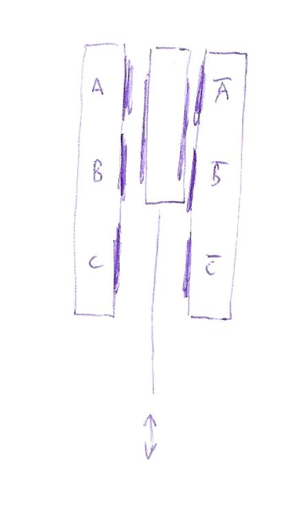
If the connections to the propeller pins are short one of the two sides would be sufficient like on the Goertzel demo board. However I'd use differential (inverted/non-inverted) signals so that the capacitance of the cables have less influence. The final output signal depends on the capacitance ratio of A-B vs. B-C (and A-B inverted vs. B-C inverted) only like in a wheatstone bridge. The absolute values of the individual caps don't matter. This should make the sensor less sensitive to mechanical tolerances (horizontal play, dielectric wear), temperature change, dirt and so on.
I also thought about using a lever+fulcrum or rack+pinion mechanism to drive a rotary encoder but this is all to complicated if simpler solutions exist with purely linear movement.
The capacitor plates can be made out of standard FR4 PCB material with the copper layer as electrodes and the solder mask as dielectric.
When I was working in the high-vacuum metallization (evaporation/sputtering) with different materials (aluminum/copper/gold/silver/magnesium/silicon/cadmium/...) on the roll-coaters (a machine that applied a thin layer of aluminum, thickness measured in angstrom's, over a 10km roll of plastic film or paper (used eg for paper capacitors/the aluminated paper in cigarette boxes/in food industry like plastic bag of chipster/....) using a high-vacuum chamber for the process, the thickness of the deposition was controlled:
Over a roll width of eg 1.5m there was ten/twelve sources of evaporation made of an silicon "boat" kept between two copper bars delivering the power. The boat is essentially a shaped diode which, when heated, melts the 1mm aluminum wire feed to it with a stepper motor. Care must be taken to not make the aluminum bath to big otherwise it creates a short between the copper bars routing the power through the aluminum bath instead of the silicon "boat" and thus loosing the temperature with the consequence of solidifying the bath.
The power applied on the boat at the end made the thickness on the film. So both, the motor speed and the power on the boat was controlled from the RF feedback. And every source, along the width of the roll had its own closed-loop control working very precisely. A 10km roll was metalized in about 4h IIRC (including the high-vacuum 10e-4mbar pump-time).
@ManAtWork so perhaps your idea of glass or pfte pipe inside the liquid bath can be elaborated in using an RF antenna inside the pipe and an receiver one under the cover and measure how much the liquid Sn is attenuating the RF signal.
An other option, since the liquid Sn is conductive at 250° and its conductivity up to 900° is also very stable in time, may be the measurement of capacitance between two electrodes of which one is isolated from the bath and the other is the bath itself
If you're willing to look in the RF direction, you could dip a wire (gray iron bar?) in the pot, connected to an RF signal generator and power meter. The lowest frequency that gives you a peak in your power reading will be a λ/4 stub.
10cm = 750MHz
15cm = 500MHz
5cm = 1500MHz
I don't know if this was already mentioned or not, or if it's precise enough, but could you point a laser ping into the pot through a glass window?
Plenty of options here. What i'd do would be to go for the simplest and cheapest feasible solution.
I think going with the capacitive sensing idea seems like the good candidate to start with or the Time-of-Flight ranging sensor, whichever suits best.
The topic starts drifting toward the famous "barometer question" and the answers of Nils Bohr. We could also release drops of water at the top of the vessel and measure the time until we hear the explosions.
While there are some really good ideas I simply can't test them all. This is only one of the challanges of building this soldering machines. I start with the one with the highest "chance of success" vs. cost ratio.
+1
Right. One needs to put a stop to pondering options and start experimenting with one that seems most promising.
Sometimes it helps to see how others are doing it:
https://www.micro-epsilon.com/applications/branch/Elektronikproduktion/Schwallloetanlagen-Loetwellenhoehenmessung/
-Phil
Yes, if you drive that Sin and Cos, a passive coupling plate will sweep the pickup plate phase angle as it moves.
Or, you could make a Triangle wave Pin oscillator using the plate-C and then check the ratio of the frequencies - that's more like a touch sensor.
Thanks, Phil. This is great! Not that the eddy current inductive sensor is something I didn't know. But a change of perspective is sometimes really inspiring!
We could do it the other way round. Instead of measuring the tin level and adjust the pump motor speed accordingly to get the same fountain height at the nozzle we could simply move the nozzle below a simple standard sensor like an optical barrier or a proximity sensor. Then spin the pump up with increasing speed until the fountain reaches the desired level. We can then use the required speed of the motor to reversely calculate the tin level. That not only allows compensation of the tin level but we also find out if the pump, pipe or nozzle is clobbered and requires cleaning. And we totally get rid of the need to place anything into the pot where the conditions are not good for electronics or precision mechanics.
I wonder why I haven't noticed this possibility earlier. Sometimes we set our focus to the wrong detail of the overall problem.
")
A disadvantage of the nozzle vs. reservoir tin level measurement is that it needs extra time and interruption of the soldering process. But if we do it twice, once before and once after soldering a board the tin consumption can be recorded and extrapolated so that we can predict the required intervals for checking the level and re-fill.
I'll try to finish the Goertzel sensor as an exercise, anyway.
The eddy current approach, per Phil’s link, could employ TI’s LDC1000 inductance to digital converter:
https://www.ti.com/product/LDC1001?keyMatch=LDC1000
No moving parts, no direct contact, dead simple construction, and immunity from dross fouling; what’s not to like?
Yes, interesting. If we had a limited and boring standard microprocessor I wouldn't mind spending $3+ for an external converter (or $100+ for the eval board which is at least available, right now, the bare chip isn't). But come on, we have the Propeller2. I think it can do almost everything the LDC1000 can do. It can measure inductance, resonant frequency, Q factor all in software.
Spot on !
The added bonus is that you only do it once in software and then can reproduce the functionality at almost no cost. Not to mention the easy path to enhance this functionality. Contrary to what you can achieve with separate hardware, that costs money with every single piece. And not only that.
That would be great to implement the eddy current LCR sensing on the Prop2, a nice demo of its capabilities. I'm interested in how you would go about it. The Prop2 could maybe even do multiple channels, like some of the application specific HID chips that TI now offers in the LDC lineup.
I'm still happily stuck with the Prop 1, which simply does not have that capability without external support. I did buy into the original LDC1000 and EVM board when it first came out, my goal being toroidal water conductivity measurement. The EVM board was a great help for proof of concept.
By the way, the bare chip LDC1101 is in stock at several distributers. (But then you have to contend with the 3mm, 10-pin VSON package!). The original LDC1000 is listed as obsolete.
I have to practice a little more with the Goertzel analyzer. I took my first exercise, the capacitive position sensor from post #45 is working. It is fairly linear in the range where the moving plate overlaps all three electrodes of the stator plate. I just had to adjust the gain and the scope range a little bit.
  dacpins   := 32 addpins 3
  adcpin    := 38
  adcmag    := 2 ' gain 10x

  frequency := 1000_000 ' 1MHz
  cycles    := 100
  phase     := 0

  coginit(newcog, @goertzel, @dacpins)

  debug(`scope_xy s 'Goertzel' samples 10 dotsize 20 size 300 range 1500_000 polar)

  repeat
    waitms(10)
    debug(`s `(power, angle))
Next exercise will be how to build an eddy current proximity sensor...
One more no-moving-parts idea. Wrap a few turns of wire around one end of an old ferrite loopstick core. Dip the other end in the solder. Being a ceramic, it should handle the heat.
Anyway, connect a cap in parallel with the coil to make a resonant tank. While the resonant frequency of the tank won't change with height, the q should change very significantly as a shorted sleeve (the solder) is slid over (covers deeper) the end of the stick, increasing the coupling between the coil and the solder. This would basically be the inductive measurement mentioned elsewhere, but would allow running at a much lower frequency and further distance.
So I know this is old but several years ago I was asked to come up with a way to measure the level of a tank which contained very hot oil. Unable to find a suitable level sensor, I used a brass float attached to a colored target by a stiff rod and looked at the target with a PIXY cam (CMU Cam) which can output the Y coordinate of the target. Every few seconds, turn on the light and look at how high the target is. Kind of an oddball approach, but damn it is still working today :-)
One of Murphy’s Laws of Combat:
If it’s stupid and it works, then it’s not stupid.
Hmm, I'll bite. If it's stupid and it works then good chance it's a grenade with its pin pulled.
Using a camera isn't stupid. It might be overkill but if it still pays then that's not a problem.
I always the meaning was clear, but perhaps not:
Like filling socks with explosive and using axle grease on the outside as an adhesive to make something like a satchel explosive to disable tank tracks (as seen in Saving Private Ryan). At first glance it looks like a stupid idea, but it works, so it isn’t.
I agree that using a camera isn’t stupid if it works… that was kinda the point.
I think I see, the "Law" will be about team brainstorming of ideas. Naturally, without trying it, there is many assumptions on the table about how an idea would develop and function. So the "and it works" part is actually an unknown at the time.