Also you might want to double check that your DVI connector pinout is correct if you made your own board component. Things like reversing the footprint pinning are easy to do by mistake with male-female connectors.
Rogloh and I have the same Dell monitor, that has a DVI but not HDMI connector. We've both done a fair bit of successful testing with that setup.
Not sure about Roger but I use a HDMI to DVI molded cable - it has an hdmi connector at one end that plugs into the P2 digital video accessory board, and a DVI molded connector at the other end that goes to the monitor.
If you get really stuck I''ll take an ohmeter to that and buzz out the P0..7 connections through to various DVI pins. It should be something fairly simple
No, it wasn't quite that warm, but the p2 showed an elevated temperature.
Probably because everything boils down to a cooling pad.
That has brought me on the wrong track.
For reading the display values of the "normal" VGA monitors I once ran across something for the P1.
But here it was only an I²C bus if I remember correctly.
With the LCD/TFT monitors the pixel clock had to match exactly with the pixel output of the display otherwise there are unsightly washes.
With the old tube boxes this didn't matter because there are no horizontal pixels.
Modern monitors interpolate the pixels, which is not noticeable in pictures. Narrow lines then show a blur which is really noticeable.
@pic18f2550 said:
Modern monitors interpolate the pixels, which is not noticeable in pictures. Narrow lines then show a blur which is really noticeable.
All monitors, with LCD, can interpolate. It's a feature of the scan-converter that sits between the external video socket and the LCD panel. It's the bare panels that do not interpolate.
EDIT: That said, it's always good to know the native resolution of a monitor. Whole multiples scale nicer.
@pic18f2550 If you want to see what timing your monitor supports once you have read your EDID data from the I2C memory, you can use the attached open source C program I discovered online to decode it for you. You will first need to build this C program with something like this command if you are using a Unix based system with a C compiler such as gcc installed. For Windows you'll need to figure it out yourself.
MacBook-Pro$ gcc -o edid-decode edid-decode.c
You can then feed this EDID decoder program a file of hex bytes (or raw binary data I think too) collected from the device. Extracting that DDC/I2C data using the P2 is not shown here, that will be something you need to do yourself, although if you have a Mac and plug in the monitor you can use this command to get the monitor's EDID data string as hex bytes and then decode that data which simplifies things for just a one-off.
# to extract EDID on Mac OS X
ioreg -l | grep -5 IODisplayEDID
E.g. if the collected EDID hex data from the monitor's i2c FLASH/EEPROM was this:
For native DVI/HDMI, it's limited by link speed, which is 10x the pixel/dot rate. Prop2, overclocked, maxes out around 350 MHz. Which is 35 Mpixels/s. Any resolution that fits within this is doable. 35e6 / 50 vsync = 700,000 (vtotal x htotal). Reduced blanking allows hblank to be as low as 96 dots and vblank can be less than 10 lines.
Square-root of 700k = 836.7. That gives a hint to start from. If you want 16:9 display aspect with square aspect pixels then 1024x576 is suitable for 50 Hz display. If you want 60 Hz display then 960x540 is better choice.
An option is to go thru a LVDS FPD-link route, relying on P2 DVI mode to basically output just 7 bits per color per pixel, and just zeroing the fourth data lane, in cases the display supports it (most of the one I've studied do it, without problems).
This would limit the color selection to 18 bpp, but seems to not be a problem pic18f2550 cares too much.
Sending each color literally, and programming the streamer nco rollover to grab fresh data each seven clocks seems a bit wastefull, memory-consumption-wise, but can be done, without problems.
Also those LCD displays seems to happyly accept lower scan rates, wich will help a lot.
As for the conversion from P2 output-levels to LVDS, perhaps the better option is to use standard available ic's, able to convert them to the aproppriate differential levels, the displays will be confortable to work with.
P.S. Sure, by rolling the streamer NCO at seven clocks per pixel, the pixel rate will be scaled-up, then, e.g., at 350 MHz, it would give a nice 50 Mpixels/second (10/7), wich is really something to consider.
Also, if one don't minds spending a bit of time with the rendering, each 10 pixels/commands would occupy only seven longs, and the memory leveraging ratio will be maximized (30/32).
Due the fact that LVDS drivers will convert single-lane LVCMOS to differential signaling, and that two streamers can be overlapped, each one occupying only four alternate pins (three, in fact, because the clocks needs to be controlled by smart pins, to be shaped 3/4, as required by FPD-link rules), each group of eight pins, originally meant to output HDMI signalling, would be able to carry two complete FPD-links, at the same time, wich is a big win too.
To avoid too much crosstalk/interference, each link should be routed at each side of the pcb. Will need to coexist with four stubs, due to the transposing vias, at one of the links, but four planes could ensure enough shielding, and better routing perspectives, in general.
Back in 2020, there were some efforts from @n_ermosh registered at the following thread:
@pic18f2550 said:
What is the maximum resolution possible with the P2 at 16/24bit?
The memory should not be considered.
@evanh said:
For native DVI/HDMI, it's limited by link speed, which is 10x the pixel/dot rate.
For analog VGA output you can do even better and output 1920x1200 60Hz 24bpp if you can generate sufficient internal data to feed the output using other COGs. This can be converted into HDMI externally with a cheap ~$15AUD adapter.
With some external PSRAM 16bit wide you could probably just about source a full frame buffer at this same resolution with 16 bit colour but you'd not have much bandwidth left over to write this buffer, or you might have to drop the frame rate a little to allow more memory bandwidth. I've certainly managed 8bpp already at this resolution.
It's possible to get 1920 pixels on a line with a VGA to HDMI adapter, or via a TFP410 RGB parallel TMDS encoder device, or from P2 pins directly via DVI/HDMI, with the latter case only if your display can accept very low refresh rates.
I have not had good experiences with VGA to HDMI converters.
They are always sufficient for pictures or films.
But they are completely unsuitable for representations such as in the CAD field.
HDMI will probably only be suitable for the future when the image information is shifted out at more than 1/10 of the system clock.
@pic18f2550 said:
I have not had good experiences with VGA to HDMI converters.
They are always sufficient for pictures or films.
But they are completely unsuitable for representations such as in the CAD field.
If scaling is involved, I'd agree. Although the particular converter I used seemed to have pixel perfect alignment when I examined it on my monitor in a 1920 pixel wide mode which is the native width of the monitor I used. In some cases I did notice some sort of colour level compression - maybe it was conversion into 16-235 levels or some such thing, black seemed dark gray but it might have been related to incorrect DVI input settings on my monitor. Not too sure, didn't delve into that.
HDMI will probably only be suitable for the future when the image information is shifted out at more than 1/10 of the system clock.
Or use a TFP410 type of TMDS encoder device if you need a full digital path out of the P2.


Comments
Also you might want to double check that your DVI connector pinout is correct if you made your own board component. Things like reversing the footprint pinning are easy to do by mistake with male-female connectors.
Rogloh and I have the same Dell monitor, that has a DVI but not HDMI connector. We've both done a fair bit of successful testing with that setup.
Not sure about Roger but I use a HDMI to DVI molded cable - it has an hdmi connector at one end that plugs into the P2 digital video accessory board, and a DVI molded connector at the other end that goes to the monitor.
If you get really stuck I''ll take an ohmeter to that and buzz out the P0..7 connections through to various DVI pins. It should be something fairly simple
There's a jumper on the Eval Board that supplies 5 Volts to the accessory headers. Without it set, there is no 5 Volts.
EDIT: Oh, you're using the Edge Board. Does the carrier even have 5 Volts on those accessory headers?
I have found the root of the evil.
A completely uninitiated pin has spit in my soup.
I have checked everything on the adapter except the Smile pin.
3,3V pin has a termination with ground.
With this nothing can go.
Let's see how I get a soldering iron in the hotel.
Cool. Or hot - the regulator will be at finger burning temperature.
No, it wasn't quite that warm, but the p2 showed an elevated temperature.
Probably because everything boils down to a cooling pad.
That has brought me on the wrong track.
When I have fixed the problem I will continue.
Thank you.
Question.
What do you use to convert your images to 16bit format?
Photoshop
I don't have Photoshop, and I'm not going to buy it anymore.
I have found an online converter on the net.
Let's see if something useful comes out.
I noticed that the BMP header is not constant but that its length is different.
With me it is now 54 bytes long.
With the right info, you should be able to embed the file correctly.
I use GIMP.
Has anyone ever read the DDC channel?
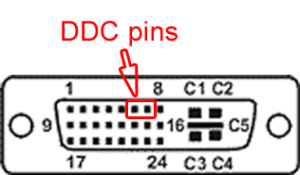
Not seen anyone use ddc here…
For reading the display values of the "normal" VGA monitors I once ran across something for the P1.
But here it was only an I²C bus if I remember correctly.
With the LCD/TFT monitors the pixel clock had to match exactly with the pixel output of the display otherwise there are unsightly washes.
With the old tube boxes this didn't matter because there are no horizontal pixels.
Modern monitors interpolate the pixels, which is not noticeable in pictures. Narrow lines then show a blur which is really noticeable.
All monitors, with LCD, can interpolate. It's a feature of the scan-converter that sits between the external video socket and the LCD panel. It's the bare panels that do not interpolate.
EDIT: That said, it's always good to know the native resolution of a monitor. Whole multiples scale nicer.
As with pretty much any media format conversion, FFMPEG is your friend, though it's a bit of a pig to install on windows.
ffmpeg -i input_image.png -f rawvideo -pix_fmt rgb565le output_file.datwill convert the image into raw 16bpp data.If you want to resize it, you can do
ffmpeg -i input_image.png -vf scale=640:512 -f rawvideo -pix_fmt rgb565le output_file.datThe EEPROM in the monitor should behave like an AT24C02.
So an I²C bus.
I'll take care of that later, but first there must be a picture.
@pic18f2550 If you want to see what timing your monitor supports once you have read your EDID data from the I2C memory, you can use the attached open source C program I discovered online to decode it for you. You will first need to build this C program with something like this command if you are using a Unix based system with a C compiler such as gcc installed. For Windows you'll need to figure it out yourself.
You can then feed this EDID decoder program a file of hex bytes (or raw binary data I think too) collected from the device. Extracting that DDC/I2C data using the P2 is not shown here, that will be something you need to do yourself, although if you have a Mac and plug in the monitor you can use this command to get the monitor's EDID data string as hex bytes and then decode that data which simplifies things for just a one-off.
E.g. if the collected EDID hex data from the monitor's i2c FLASH/EEPROM was this:
then it can be decoded using this, and it will show some details such as supported resolutions/timings:
MacBook-Pro$ ./edid-decode edid3.txt Extracted contents: header: 00 ff ff ff ff ff ff 00 serial number: 41 2f bd 00 00 00 00 00 00 11 version: 01 03 basic params: 80 6e 3e 78 2a chroma info: d7 b3 ae 51 50 94 23 0c 4a 47 established: 21 08 00 standard: 81 80 01 01 01 01 01 01 01 01 01 01 01 01 01 01 descriptor 1: 66 21 50 b0 51 00 1b 30 40 70 36 00 4e 6c 42 00 00 1e descriptor 2: 01 1d 80 d0 72 1c 16 20 10 2c 25 80 4e 6c 42 00 00 9e descriptor 3: 00 00 00 fd 00 17 3d 0f 45 0f 00 0a 20 20 20 20 20 20 descriptor 4: 00 00 00 fc 00 50 49 4f 4e 45 45 52 5f 50 44 50 0a 20 extensions: 01 checksum: c7 EDID version: 1.3 Manufacturer: PIO Model bd Serial Number 0 Made in year 2007 Digital display Maximum image size: 110 cm x 62 cm Gamma: 2.20 DPMS levels: Off RGB color display First detailed timing is preferred timing Display x,y Chromaticity: Red: 0.6826, 0.3173 Green: 0.3134, 0.5810 Blue: 0.1386, 0.0498 White: 0.2890, 0.2802 Established timings supported: 640x480@60Hz 4:3 HorFreq: 31469 Hz Clock: 25.175 MHz 800x600@60Hz 4:3 HorFreq: 37900 Hz Clock: 40.000 MHz 1024x768@60Hz 4:3 HorFreq: 48400 Hz Clock: 65.000 MHz Standard timings supported: 1280x1024@60Hz 5:4 HorFreq: 64000 Hz Clock: 108.000 MHz Detailed mode: Clock 85.500 MHz, 1102 mm x 620 mm 1360 1424 1536 1792 hborder 0 768 771 777 795 vborder 0 +hsync +vsync VertFreq: 60 Hz, HorFreq: 47712 Hz Detailed mode: Clock 74.250 MHz, 1102 mm x 620 mm 1920 2448 2492 2640 hborder 0 540 542 547 562 vborder 0 +hsync +vsync interlaced VertFreq: 50 Hz, HorFreq: 28125 Hz Monitor ranges (GTF): 23-61Hz V, 15-69kHz H, max dotclock 150MHz Monitor name: PIONEER_PDP Has 1 extension blocks Checksum: 0xc7 (valid) CTA extension block Extension version: 3 41 bytes of CTA data Video data block VIC 20 1920x1080i@50Hz 16:9 HorFreq: 28125 Hz Clock: 74.250 MHz VIC 5 1920x1080i@60Hz 16:9 HorFreq: 33750 Hz Clock: 74.250 MHz VIC 31 1920x1080@50Hz 16:9 HorFreq: 56250 Hz Clock: 148.500 MHz VIC 16 1920x1080@60Hz 16:9 HorFreq: 67500 Hz Clock: 148.500 MHz VIC 18 720x576@50Hz 16:9 HorFreq: 31250 Hz Clock: 27.000 MHz VIC 3 720x480@60Hz 16:9 HorFreq: 31469 Hz Clock: 27.000 MHz VIC 19 1280x720@50Hz 16:9 HorFreq: 37500 Hz Clock: 74.250 MHz VIC 4 1280x720@60Hz 16:9 HorFreq: 45000 Hz Clock: 74.250 MHz VIC 17 720x576@50Hz 4:3 HorFreq: 31250 Hz Clock: 27.000 MHz VIC 2 720x480@60Hz 4:3 HorFreq: 31469 Hz Clock: 27.000 MHz VIC 22 1440x576i@50Hz 16:9 HorFreq: 15625 Hz Clock: 27.000 MHz VIC 7 1440x480i@60Hz 16:9 HorFreq: 15734 Hz Clock: 27.000 MHz VIC 21 1440x576i@50Hz 4:3 HorFreq: 15625 Hz Clock: 27.000 MHz VIC 6 1440x480i@60Hz 4:3 HorFreq: 15734 Hz Clock: 27.000 MHz VIC 32 1920x1080@24Hz 16:9 HorFreq: 27000 Hz Clock: 74.250 MHz VIC 1 640x480@60Hz 4:3 HorFreq: 31469 Hz Clock: 25.175 MHz Audio data block Linear PCM, max channels 2 Supported sample rates (kHz): 48 44.1 32 Supported sample sizes (bits): 24 20 16 Speaker allocation data block Speaker map: FL/FR - Front Left/Right Vendor-specific data block, OUI 000c03 (HDMI) Source physical address 1.0.0.0 Supports_AI DC_36bit DC_30bit DC_Y444 Maximum TMDS clock: 225MHz Video latency: 17 Audio latency: 17 Interlaced video latency: 34 Interlaced audio latency: 34 Extended tag: Video capability data block YCbCr quantization: No Data (0) RGB quantization: Selectable (via AVI Q) (1) PT scan behaviour: Support both over- and underscan (3) IT scan behaviour: Always Underscanned (2) CE scan behaviour: Always Overscannned (1) Underscans PC formats by default Basic audio support Supports YCbCr 4:4:4 Supports YCbCr 4:2:2 1 native detailed modes Detailed mode: Clock 74.250 MHz, 1102 mm x 620 mm 1920 2008 2052 2200 hborder 0 540 542 547 562 vborder 0 +hsync +vsync interlaced VertFreq: 60 Hz, HorFreq: 33750 Hz Detailed mode: Clock 27.000 MHz, 1102 mm x 620 mm 720 732 796 864 hborder 0 576 581 586 625 vborder 0 -hsync -vsync VertFreq: 50 Hz, HorFreq: 31250 Hz Detailed mode: Clock 27.000 MHz, 1102 mm x 620 mm 720 736 798 858 hborder 0 480 489 495 525 vborder 0 -hsync -vsync VertFreq: 59 Hz, HorFreq: 31468 Hz Checksum: 0xc1 (valid)OK 960x600 is a bit too much.
960x600x8bit = 576kB
I want to make a frame around the 640x256 (163,84kByte) output window.
Top and bottom 172 lines to center the image in height.
To center the width I will probably use the video memory.
A colored frame would be nice.
What is the maximum resolution possible with the P2 at 16/24bit?
The memory should not be considered.
For native DVI/HDMI, it's limited by link speed, which is 10x the pixel/dot rate. Prop2, overclocked, maxes out around 350 MHz. Which is 35 Mpixels/s. Any resolution that fits within this is doable. 35e6 / 50 vsync = 700,000 (vtotal x htotal). Reduced blanking allows hblank to be as low as 96 dots and vblank can be less than 10 lines.
Square-root of 700k = 836.7. That gives a hint to start from. If you want 16:9 display aspect with square aspect pixels then 1024x576 is suitable for 50 Hz display. If you want 60 Hz display then 960x540 is better choice.
An option is to go thru a LVDS FPD-link route, relying on P2 DVI mode to basically output just 7 bits per color per pixel, and just zeroing the fourth data lane, in cases the display supports it (most of the one I've studied do it, without problems).
This would limit the color selection to 18 bpp, but seems to not be a problem pic18f2550 cares too much.
Sending each color literally, and programming the streamer nco rollover to grab fresh data each seven clocks seems a bit wastefull, memory-consumption-wise, but can be done, without problems.
Also those LCD displays seems to happyly accept lower scan rates, wich will help a lot.
As for the conversion from P2 output-levels to LVDS, perhaps the better option is to use standard available ic's, able to convert them to the aproppriate differential levels, the displays will be confortable to work with.
P.S. Sure, by rolling the streamer NCO at seven clocks per pixel, the pixel rate will be scaled-up, then, e.g., at 350 MHz, it would give a nice 50 Mpixels/second (10/7), wich is really something to consider.
Also, if one don't minds spending a bit of time with the rendering, each 10 pixels/commands would occupy only seven longs, and the memory leveraging ratio will be maximized (30/32).
Due the fact that LVDS drivers will convert single-lane LVCMOS to differential signaling, and that two streamers can be overlapped, each one occupying only four alternate pins (three, in fact, because the clocks needs to be controlled by smart pins, to be shaped 3/4, as required by FPD-link rules), each group of eight pins, originally meant to output HDMI signalling, would be able to carry two complete FPD-links, at the same time, wich is a big win too.
To avoid too much crosstalk/interference, each link should be routed at each side of the pcb. Will need to coexist with four stubs, due to the transposing vias, at one of the links, but four planes could ensure enough shielding, and better routing perspectives, in general.
Back in 2020, there were some efforts from @n_ermosh registered at the following thread:
https://forums.parallax.com/discussion/171516/p2-fpd-link-lvds-displays
For analog VGA output you can do even better and output 1920x1200 60Hz 24bpp if you can generate sufficient internal data to feed the output using other COGs. This can be converted into HDMI externally with a cheap ~$15AUD adapter.
With some external PSRAM 16bit wide you could probably just about source a full frame buffer at this same resolution with 16 bit colour but you'd not have much bandwidth left over to write this buffer, or you might have to drop the frame rate a little to allow more memory bandwidth. I've certainly managed 8bpp already at this resolution.
Ok, so generating a line with 1920 pixels is not possible with the P2.
I will probably make do with 960 pixels.
It's possible to get 1920 pixels on a line with a VGA to HDMI adapter, or via a TFP410 RGB parallel TMDS encoder device, or from P2 pins directly via DVI/HDMI, with the latter case only if your display can accept very low refresh rates.
I did 1024x576 @ 50 Hz, signalling 624 lines and 1140 total horizontal pixels (to get Atari/Amiga compatible timings) @ 354 MHz
As @rogloh said an adapter can give 1080p.
I have a couple different ones from Amazon that give 1080p + sound for around $10 from VGA.
Also, I have done native 1080p to a DLP projector that takes a 10Hz input amazingly.
I did VGA 1920x1080 pixels as a test for a logic analyser when we received the first Rev A glob tops. So 1080p is certainly possible.
I have not had good experiences with VGA to HDMI converters.
They are always sufficient for pictures or films.
But they are completely unsuitable for representations such as in the CAD field.
HDMI will probably only be suitable for the future when the image information is shifted out at more than 1/10 of the system clock.
If scaling is involved, I'd agree. Although the particular converter I used seemed to have pixel perfect alignment when I examined it on my monitor in a 1920 pixel wide mode which is the native width of the monitor I used. In some cases I did notice some sort of colour level compression - maybe it was conversion into 16-235 levels or some such thing, black seemed dark gray but it might have been related to incorrect DVI input settings on my monitor. Not too sure, didn't delve into that.
Or use a TFP410 type of TMDS encoder device if you need a full digital path out of the P2.