

P2 HDMI Monitor resolution 1920x1200 and Videodata 640x256 Pixel
 pic18f2550
Posts: 400
pic18f2550
Posts: 400
Hello,
does anyone know a HDMI driver to create the format 640x512.
If the resolution is larger, that is also not a problem, that could be worked around with a frame.
As rgb 16Bit would also be sufficient.
Comments
This can be done, I've done 720p and 1080p. But, the problem is that the refresh rate is going to be less than 60 Hz at these resolutions.
Some display devices are forgiving with refresh rate, but others are not...
Issue here is that the HDMI clock can only be as fast as the P2 clock. The minimum HDMI clock is 250 MHz and that gets you 480p at 60 Hz.
The HDMI drivers I've seen are all 24bpp color. But, your color data can be less than that.
640x512 isn't too much more than 640x480, so it'll work at 60Hz fine, just have to clock at around ~270MHz
Is the pixel color information always in long format?
No, I really need 512 lines.
More lines would be no problem.
Actually 256 lines would be enough, but I don't know how the typeface will look afterwards.
With VGA with the P1, I had a lot of possibilities to change the timing, so that I hit the pixels.
Is the pixel color information always in long format?
No, can be either RGBX8888 longs, RGB565 words, RGB332 bytes, some other random formats or bytes/nibbles/pairs/bits indexing into the LUT as a palette
That resolution is nominally 50 Hz display. Which should work at the minimum 250 MHz HDMI clock. Though, I imagine higher clocks can be used anyway. Just have larger blanking times.
Just tried my video driver out with this custom timing below and was quickly able to get 640x512 resolution sent over DVI/HDMI @ 60Hz with a 252MHz P2 to my Dell LCD monitor. So yes it can be done. But YMMV depending on your own monitor's timing requirements and capabilities. An HDTV with an HDMI input might be more stringent with what it supports for example.
Of course a P2 outputting 640x512 with 16 bpp graphics is not going to all fit in hub memory if fully bitmapped, though it could do that from HyperRAM - I need to get back to finish that last bit off and finally release it (I have been holidaying somewhat away from the P2 for a while now and enjoying the summer break here). It was about 99% done the last time I'd worked on it, just documenting and adding some examples IIRC.
I have made some changes to the "Spiral Demo".
Can someone check this for me?
Since I still have no P2 board.
Yep, seems to work, producing 65 Hz video output. Tight blanking! Doesn't assemble correctly in Flexspin though. The ASMCLK macro isn't recognised.
I've attached a flexible variant of Chip's code that I hacked up some months back. There's a straight set of constants at the beginning for experimenting with. Including choosing the clock parameters individually. I've set it to 912x512 as another test case.
This is good news. I have taken it over.")

Unfortunately, the image consumes too much memory.
I still need 64k as buffer.
Does the value "width" really have to be set to 912 or is 640 enough?
What is output on the HDMI when the value is smaller.
Does rdfast stay in the range "##width*height/64" and starts again from the beginning,
or does it leave the range?
Why the thought.
I am considering moving the "rdfast" command into the range from the "line" generation.
If "rdfast" should move only in the range "##width*height/64", then one could generate with a loop leader each line a new starting point.
First, the "hbackp" would be omitted as memory.
Second, the image would be shifted, but with a bit of software the image could be corrected.
field mov hsync0,sync_000 'vsync off mov hsync1,sync_001 callpa #vbackp,#blank 'top blanks mov i,##height 'set visible lines mov iy,##bitmap 'Startpunkt setzen line rdfast ##width*/64,iy 'set rdfast to wrap on bitmap add iy,ix call #hsync 'do horizontal sync xcont m_rf,#0 'do visible line djnz i,#line 'another line? callpa #vfrontp,#blank 'bottom blanks ix long width iy res 1 i res 1Any multiple of 8 pixels works for horizontal. Hence why 912 was just an example.
DVI/HDMI seems to be quite good at conveying the resolution, when compared to LCDs scaling VGA signaling.
With RDFAST size specified as zero, it is unbound and will naturally loop at 1 MB. With any other size, like above, the RDFAST will loop at that range.
Yep, very doable.
Blanking takes no hubRAM. All the blanking streamer (XCONT) modes are direct register data source, ie: it takes the S operand as its data directly. The FIFO index into hubRAM is unchanged until the next bitmap portion (labelled m_rf).
If I have understood all this correctly, this setting should be correct.
This would make it easier to handle.
width = 912 - 272 htotal = width + hfrontp + hpulse + hbackp = 1104 Pixel height = 512 vtotal = height + vfrontp + vpulse + vbackp hfrontp = 16 + 136 hpulse = 80 hbackp = 96 + 136 vfrontp = 3 vpulse = 1 vbackp = 12That works. Though, there's more flexibility with both the clock rate and the scan rates. I've got that example set at 330 MHz clock rate and vertical scan is 56 Hz, therefore you can up the scan rates, by not having such large hblanking, and/or lower the clock rate toward the minimum 250 MHz.
BTW: I've not read any documentation on it ( I saw something in some source code that gave me this conclusion), but I suspect that VRR can be triggered, on VRR capable monitors, simply by making the vertical blanking length a dynamic parameter. Whether it's back or front porch, both or even the sync pulse length, I couldn't guess.
A driver dynamization, by passing an array, would be helpful, because then the resolutions can be changed and if necessary adapted during operation.
The pixel clock rate and the number of pixels are related and decide the _clkfreq.
An integration of a USB driver is therefore a bit complicated.
But I don't need it at this point.
At most the X/Y coordinates and which mouse pointer type would be interesting.
But I have this in another post already in work.
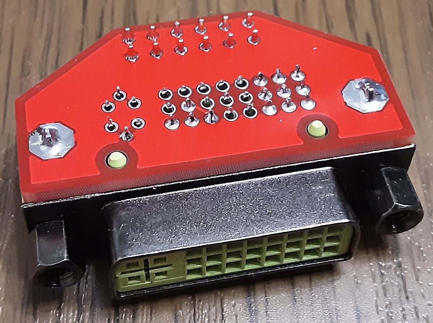
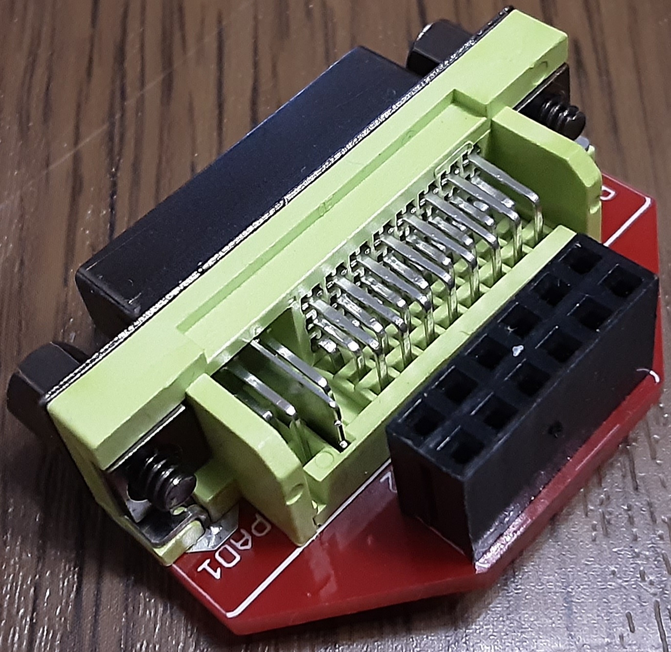
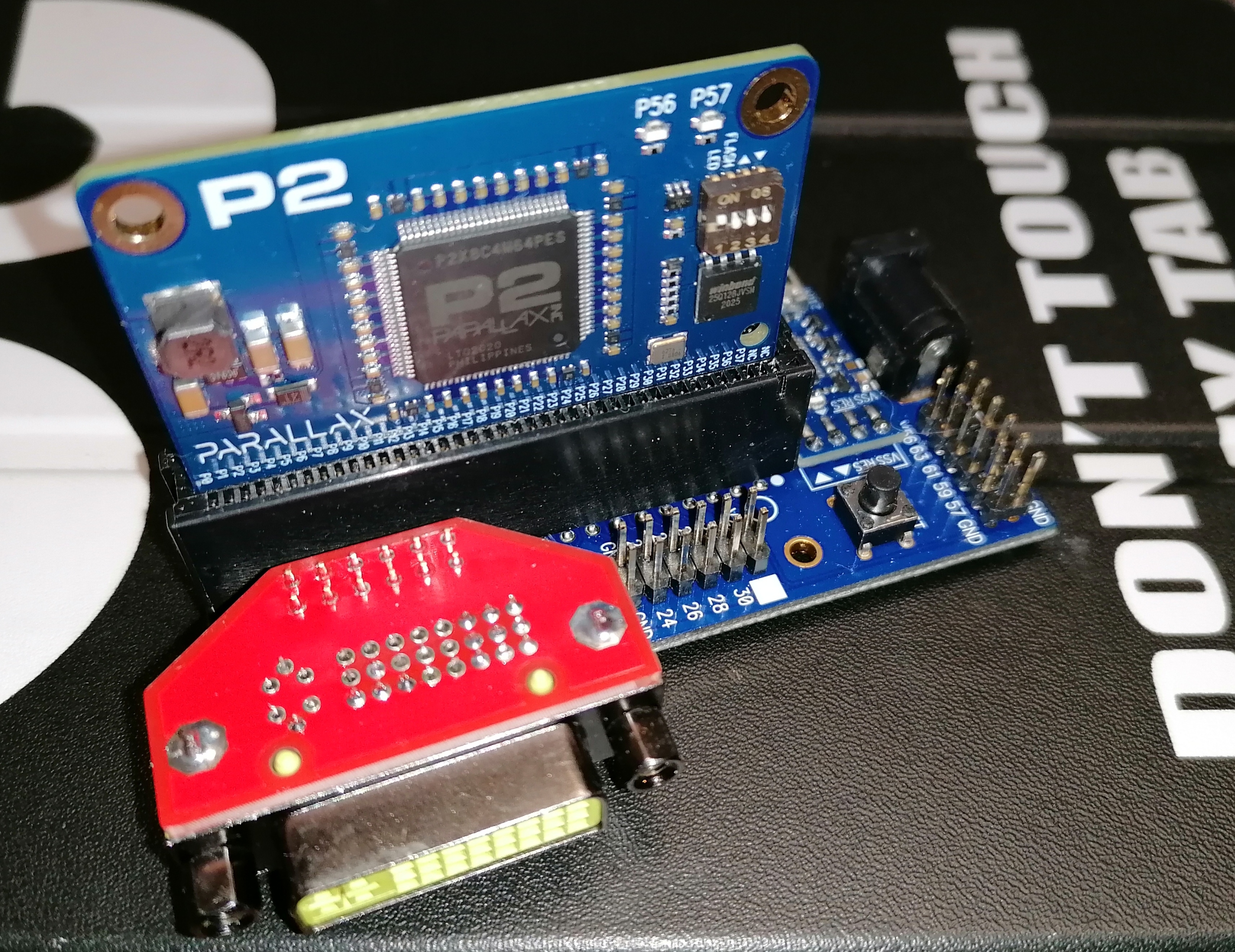
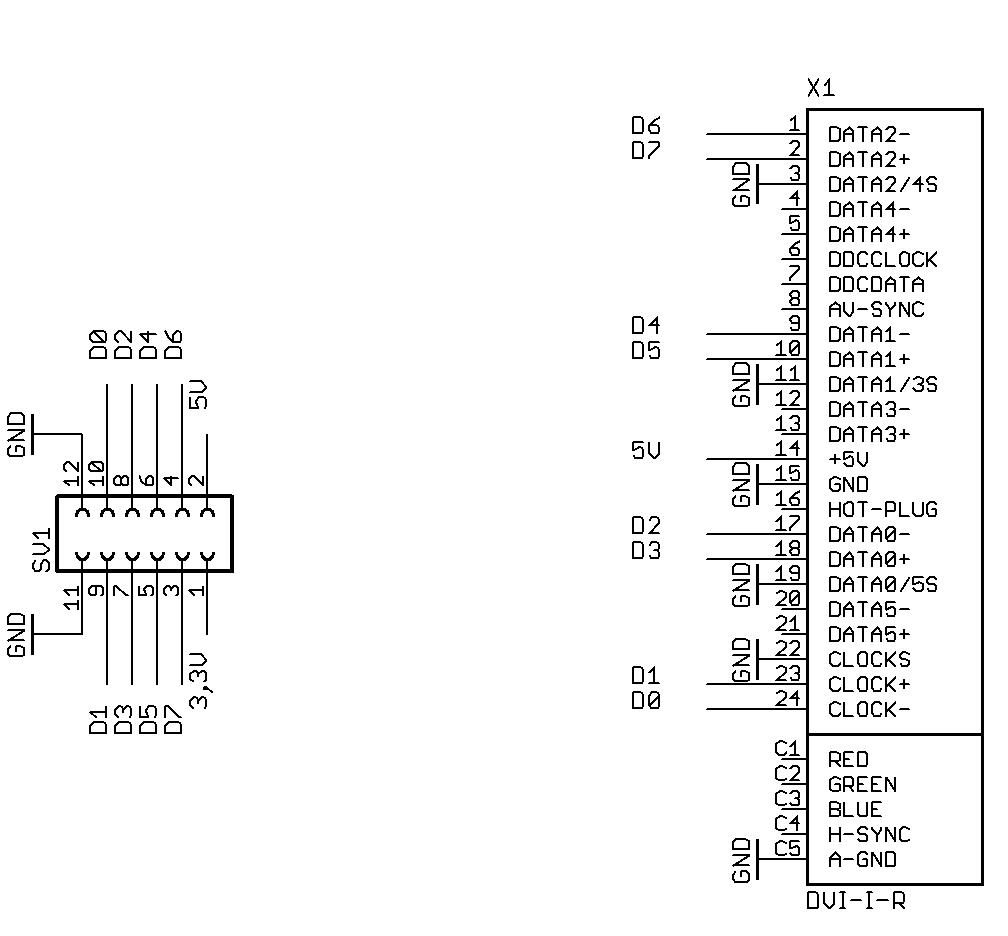
I once carved myself a DVI adapter.
Looks handy for older monitors and to avoid cable dongles. DVI was nice way back when, unfortunately it was even bulkier than VGA though and died out once HDMI was used in PC monitors.
I'd actually like to get a Dual-Link DVI working with a P2 somehow for a 2560x1600 monitor but it first requires conversion from two parallel video outputs (or VGA), given that the P2 can't output its TMDS signals much faster than about a 36MHz pixel rate.
Would it be worth trying to put a tfp410 on a board with a prop?
Well, that could still double the Prop2's native DVI bandwidth by using two streamers without any dongle.
I'm not sure this buys you anything unless you also use something like HyperRam to store the image.
Got a board that uses tfp410 to output image from EVE3 GPU though. That might be interesting, if it works...
Yeah but only for those monitors that can take dual link inputs. And these will be very high resolution ones - I've only ever seen it used with those first 2560x1600 monitors that came out in the early to mid 2000's, because you can still do 1920x1200 with single link DVI (using reduced blanking). I think a pair of tfp410's might work if you could get the pixel phase right on the pair but this eats up almost all the P2 pins if you want 24bpp colour and no spare pins for external memory to source it. The simple way, if you can get the pixel sync to work right (and it's a big if), is probably to use two of those cheap VGA to HDMI converters/chips.
If I can get a hold of some of those chips I might make a breakout for it to try out.
I do not want to use an extra chip.
I would rather burn a 2nd P2.
For a second monitor with 1920x1080x8bpp rgbi8 the memory is not enough anyway (518400 bytes).
Something is stuck.
Since I only have the small board, I set the HDMI pin to 8.
The HDMI demo is loaded.
The LED flashes.
The monitor does not start.
The P2 warms up well.
Is there an explanation for this command?
setcmod #$100In the PASM docu you can wish 512 values.
@pic18f2550 said:
From the P2 H/W documentation
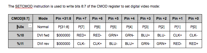
The other bits in the CMOD register are used for analog video control and are tersely described in the Colorspace Converter section.
Something doesn't fit.
setcmod #$100
but
"The SETCMOD instruction is used to write bits 8:7"
---> setcmod #$10 ?
You're losing it! setcmod #$10 is bit4.
What about the 5 volts, is that jumpered on the Eval Board? Some monitors need the 5 volts supplied.
The 5V are connected to the DVI socket pin 14.
You're not alone, by any means.
Me too, need of a new one, and some decent eyes (even just a right one, would suffice...).
I noticed some unsoldered pins in your photos... Maybe you were just doing the ones needed, but perhaps you missed one?
It should work if wired correctly...
Here's a code that works at WVGA resolution with most monitors I think. Rigged for basepin=8.
Some TVs won't take it though...