Weird Motor Behavior
 lardom
Posts: 1,659
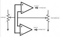
I did an experiment using two comparators to see if I could get a DC motor to behave like a servo. I connected a control-potentiometer to the inputs of two comparators, one inverting input and the other non-inverting. I did the same with the motor's feedback potentiometer using the opposite inputs. The comparator outputs were fed to an h-bridge.
I thought this would allow me to control the position of the motor without having to use a micro-controller. At worst I thought the motor would chatter as it kept trying to find the neutral point. What I got was more like Parkinsons disease because the motor would turn to the spot but shake continuously.
I have already done it with a Prop and an ADC chip. I wanted to know if I could do the same thing with a simpler circuit.
I don't know if it's worth going any further. I would love to hear an explanation for the shaking behavior.
I removed the PCB from an old servo and connected the five wires to a breadboard for the experiment.
I drew up the image below to show the basic idea.


Comments
That's it! I knew that was the correct explanation the moment I read it. Thank you.
I know from my experiments with a Prop and an ADC that I had to do those very things you mentioned in the "cure".
-Phil
I watched a video where the narrator said late model cars have a power-window control module with a "ripple counter". He said the mechanical commutator creates ripples when it changes contacts which the module uses to determine distance. I said to myself if that's true 'maybe' I can use comparators to count pulses in DC motors.
I will test diodes to see if if there is anything useful.
-Phil
It absolutely is time for me to learn how to filter out electrical noise from my motor circuits.
The feedback resistors Phil is referring to are placed between the output and +input of the comparator. They make the comparator work like a Schmitt trigger and create a dead zone around the set point. Of course they also reduce the position accuracy. The old analog drive pipetters I worked on used two high gain op amps and transistors in an H bridge drive circuit for the x and y motors, and had feedback potentiometers to adjust the dead band. They only had to get close enough to the desired position to place a tiny tube in a test tube, but still required frequent calibration. The switch to stepper motors on this equipment was a blessing.
I think I understand. I'll set up an experiment to see how the motor behaves.
EDIT: If I understand correctly, the feedback resistor would be a small resistance.
-Phil
I keep hoarding stocking up on these for small motors (under $1): https://forums.parallax.com/discussion/168432/h-bridges-of-madison-county-77-cents The Ebay link in that post is dead, so see https://www.ebay.com/itm/142061997859 Truth table at https://forums.parallax.com/discussion/download/122689/h-bridge TT MX1508.jpg
Edit: Gramps here in the forum several years ago was using relays to drive a window motor. His post contains videos showing before & after dynamic braking. https://forums.parallax.com/discussion/123305/heavy-lifting-with-gasp-relays
@erco, thanks for the links. I definitely could use motor drivers that have dynamic braking.