@JRoark said:
I covet your case! Where did you get that?
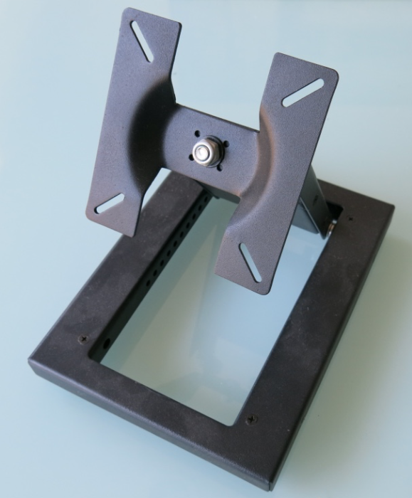
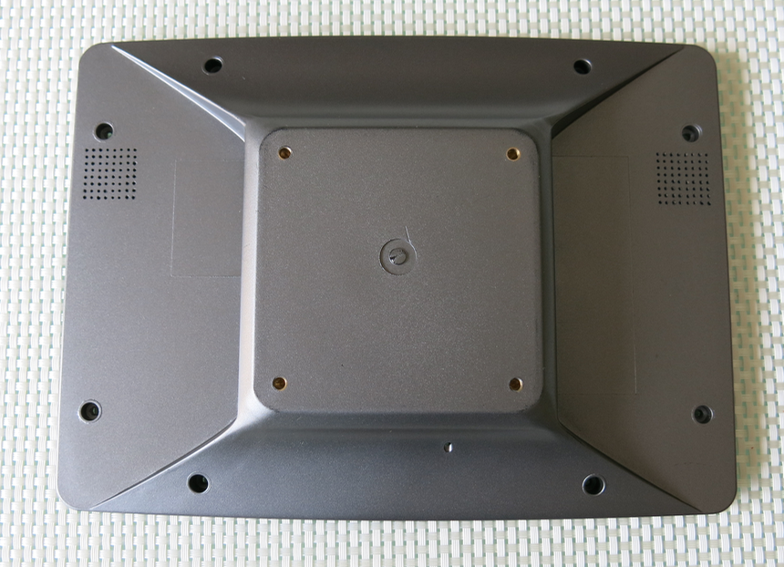
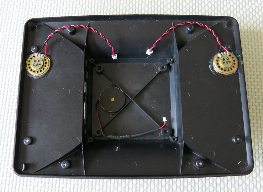
I believe it was out of an old touchscreen based POS terminal from way back (like they use in shops for cash registers etc). I even have the dusty old metal stand for it too which could come in handy. If you look on AliExpress or Alibaba, etc, I think you might find something similar these days, although probably with somewhat larger screens. This particular case shows its age as it even has a cutout for a full size USB-B socket so its probably over 15 years old! Still it's perfect for what I need and includes just the right sockets I wanted. Tricky part was locating suitable DC and audio jacks with the right height lining up with the holes - I spent some hours trawling through data sheet dimensions on Mouser etc finding matching parts. The SD, VGA, Ethernet and USB stuff are at least standard dimensions and easy to fit.
@Cluso99 said:
When I connected my real z80 pcb on top of my RetroBlade2 the P2 and regs became quite hot. I stuck on the heat sinks to the P2 cpu and regs (from a RPi set of 4) but were still hot. The RetroBlade2 was just on the desk so no airflow under either. I extended the socket pins to give a little more space between the pcbs and put a tiny 5V fan near one end - nothing special, jus sitting on the bench. Amazingly cool now
Yeah it's amazing how much cooler a P2 can run with just a little air blowing on it. When I was stress testing my P2ME2 just having that fan directing air let me run it hard and not burn my fingers on the GND hole at the back of the board.
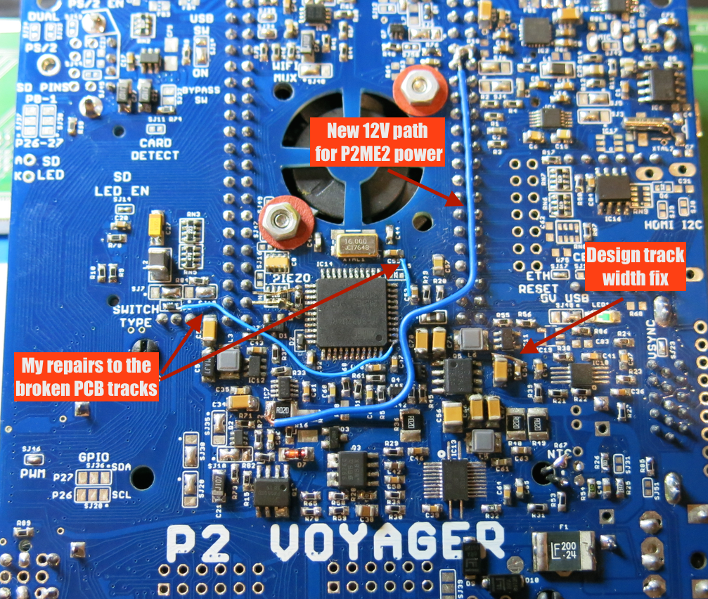
I think the P2 should be fine in my design as the fan blows air right onto it and it can crank up if under really heavy load. I've also now split my regulator loads by feeding 12V into the P2ME2 directly with an internal wiring mod so the 5V buck regulator on the Voyager board now doesn't power the P2ME2 but only powers the LCD (which pulls 750mA max at full brightness but probably more likely ~500mA at typical levels), and any external USB device and internal audio amplifier. I think its little plastic encased inductor will survive now. I do know it could cope with 1.7A but it got rather hot then (still within its rated temp) and I was a little concerned about it. So after this wiring change I'm not too worried. Probably the only issue for me now is getting sufficient fresh air into the case so I what I might do is drill some more holes if I find it is needed during summer.
Comments
There's nothing like just that tiny bit of airflow to spread things out. Makes a huge difference
I believe it was out of an old touchscreen based POS terminal from way back (like they use in shops for cash registers etc). I even have the dusty old metal stand for it too which could come in handy. If you look on AliExpress or Alibaba, etc, I think you might find something similar these days, although probably with somewhat larger screens. This particular case shows its age as it even has a cutout for a full size USB-B socket so its probably over 15 years old! Still it's perfect for what I need and includes just the right sockets I wanted. Tricky part was locating suitable DC and audio jacks with the right height lining up with the holes - I spent some hours trawling through data sheet dimensions on Mouser etc finding matching parts. The SD, VGA, Ethernet and USB stuff are at least standard dimensions and easy to fit.


Yeah it's amazing how much cooler a P2 can run with just a little air blowing on it. When I was stress testing my P2ME2 just having that fan directing air let me run it hard and not burn my fingers on the GND hole at the back of the board.
I think the P2 should be fine in my design as the fan blows air right onto it and it can crank up if under really heavy load. I've also now split my regulator loads by feeding 12V into the P2ME2 directly with an internal wiring mod so the 5V buck regulator on the Voyager board now doesn't power the P2ME2 but only powers the LCD (which pulls 750mA max at full brightness but probably more likely ~500mA at typical levels), and any external USB device and internal audio amplifier. I think its little plastic encased inductor will survive now. I do know it could cope with 1.7A but it got rather hot then (still within its rated temp) and I was a little concerned about it. So after this wiring change I'm not too worried. Probably the only issue for me now is getting sufficient fresh air into the case so I what I might do is drill some more holes if I find it is needed during summer.
Update: Here are the mods I made under the board:
