The "Artist" robot
Hello everybody,
This is my attempt to make a ground painter robot in order to scribble on large areas like street, yards or sidewalks.
The project has 3 parts:
Part 1: The main body of the robot (Chassis, electronics, Power etc.)
Part2: The painting mechanism of the robot (I have designed 3 different ways of writing. The problem is still open)
Part3: The programming procedure that makes the several drawings (letters, geometric drawings, images) into command code for the robot
I hope that youll enjoy my journey for this goal and you will find useful information as well as Im waiting for your proposals and your feedback
Part1: The main body of a robot
For this purpose we need a robot with big and strong wheels able to move comfortably.
Arlo and Eddie robots are very suitable for this purpose. Its big and strong wheels are ideal for movements on streets and sidewalks. Both robots have also a lot of space for additional development and mechanisms essentials for the painting
However on my design, I decided to keep only the 2 main wheels (Left and Right) and choose a different chassis design that is close to the Stingray robot
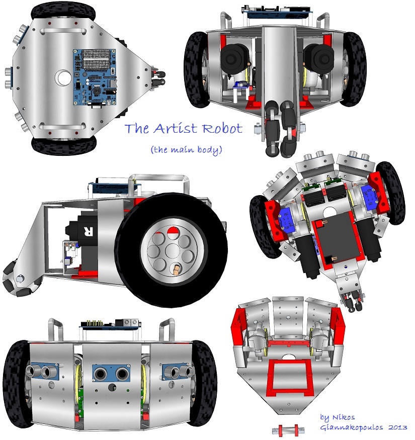
Except of the main wheels, the robot chassis has also 8 aluminum parts, 4 plastic parts from a 3d printer and an aluminum omni wheel .

The owners of a 3d printer know well, that the best way to test a 3d designed accessory is to print it and try its functionality in the real world.
Technical difficulties prevent me to do this so the only I have made till now is to gather the 8 aluminum parts of the chassis and put them together with the Motor Mount and Wheel Kit (#27971) (the wheel kit from Eddie robot).
For those who want to follow this project I strongly recommend the use the Motor Mount & Wheel Kit - Molded Plastic for many reasons (I ll explain details on my next posts.)
The entire philosophy of the robot follows the logic of the Arlo Robotic Platform System
and will be able to program it using the spin language or the Propeller C using the SimpleID tool obtaining all the advantages from the ActivityBot programming.
At the moment here are some photos from chassis parts and from a rough assembly
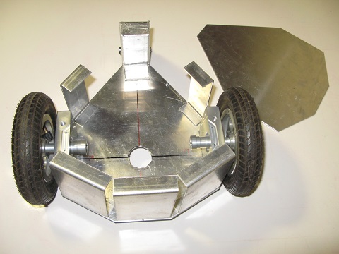
The 8 aluminum parts of the chassis

Put them together without screws ...

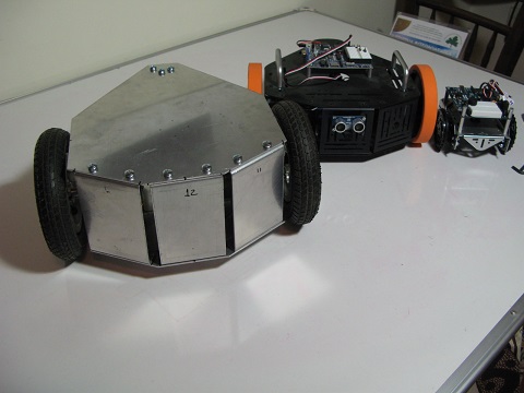
A first rough assembly in order to compare the size with the Stingray and The ActivityBot

Nikos Giannakopoulos
This is my attempt to make a ground painter robot in order to scribble on large areas like street, yards or sidewalks.
The project has 3 parts:
Part 1: The main body of the robot (Chassis, electronics, Power etc.)
Part2: The painting mechanism of the robot (I have designed 3 different ways of writing. The problem is still open)
Part3: The programming procedure that makes the several drawings (letters, geometric drawings, images) into command code for the robot
I hope that youll enjoy my journey for this goal and you will find useful information as well as Im waiting for your proposals and your feedback
Part1: The main body of a robot
For this purpose we need a robot with big and strong wheels able to move comfortably.
Arlo and Eddie robots are very suitable for this purpose. Its big and strong wheels are ideal for movements on streets and sidewalks. Both robots have also a lot of space for additional development and mechanisms essentials for the painting
However on my design, I decided to keep only the 2 main wheels (Left and Right) and choose a different chassis design that is close to the Stingray robot
Except of the main wheels, the robot chassis has also 8 aluminum parts, 4 plastic parts from a 3d printer and an aluminum omni wheel .
The owners of a 3d printer know well, that the best way to test a 3d designed accessory is to print it and try its functionality in the real world.
Technical difficulties prevent me to do this so the only I have made till now is to gather the 8 aluminum parts of the chassis and put them together with the Motor Mount and Wheel Kit (#27971) (the wheel kit from Eddie robot).
For those who want to follow this project I strongly recommend the use the Motor Mount & Wheel Kit - Molded Plastic for many reasons (I ll explain details on my next posts.)
The entire philosophy of the robot follows the logic of the Arlo Robotic Platform System
and will be able to program it using the spin language or the Propeller C using the SimpleID tool obtaining all the advantages from the ActivityBot programming.
At the moment here are some photos from chassis parts and from a rough assembly
The 8 aluminum parts of the chassis
Put them together without screws ...
A first rough assembly in order to compare the size with the Stingray and The ActivityBot
Nikos Giannakopoulos


Comments
After the Atomic Flame Deluge comes and all computers and 3D printers are dead, Nikos will reign supreme!
edit: remember Hektor, the painting robot? Still fun to watch some 9 years later. Very fluid (?) motion.
Edit: better results at the 2-minute mark at https://www.youtube.com/watch?v=2xv3lLTWNRA "Hello World"
Looks kinda like my homemade StingRay - on steroids
Yeah! That was an earlier pic before I added Ping and two Sharp IR detectors and a MCP3202 ADC chip...
The motor controller and encoder stuff is "under the hood"
It's just collecting dust in the basement now...
No sir, it's waiting for Judgement Day to become self-aware.
Actually your design was one of the sources of my inspiration.
The Chassis construction was easy and not too expensive for me. I gave the patterns from paper in a local whitesmith and I have them for 20 euros.
However the Artist is much bigger than a Stingray robot.
The Motor Mount and Wheel Kit makes this difference. As you can see from the next image there is a significance difference on the size of these two robots.
In the next posts you'll see that the Artist can carry internal even a battery same as the Arlo Robot!
erco,
No ..... this painting method is very extreme!!!!!
I would prefer something more Artistic Spray...... Chalk ...... or Sand... (remember Skryf from one of your posts?)
Nikos,
Your motors and wheels are much beefier than what I used. What size battery are you planning on using? I used a 5Ah 12V gell cell.
It will be interesting to see what it weighs when you get a finished product.
Good Luck!
- Ron
Although I have enough space for two choices
Choice A: 12V 5.4AH dimensions 90mm X100mmX 70mm
Choice B: 12V 7.2AH dimensions 150mm X95mm X65mm
I'll use the choice A because this battery is much more lighter from the second and because I don't need the use of robot for to many hours
This is one very neat robust base, ideal for taking on more serious works of art....
I think I saw somewhere (i am sure it was posted in the forum) a robot that was dropping either flour or sand along a street (ie dotmatrix style ) ... ;-)
The handles are perfect, its so difficult to tame these metal beasts....
I am also glad to see the heavy batteries are forward of the centre-line ... my S2 tends to lift its single boggy wheel on fast changes of direction.
Looking forward to seeing what you will be attaching/pouring through the "Art Port"
regards G
Yesterday was a day full of tests and printing of the Artists plastic parts.
A double HB-25 holder was the first part I made. This part designed in order to hold the two HB-25 of the robot. This part will be in the center inside the robot where my access will be limited. In order to can screw it tight on the chassis base, I put 3 secure nuts inside the plastic holder . Now I can screw this accessory on the chassis internal without hold the nut with any tool from the inside .
Another basic part of the robot is the bearing block extensions.
These two extensions must be strong in order to hold the motor mount and wheel kits from the top of the chassis.
They have a lot of plastic and best quality printing that took me 2 hours for every one......
Gareth, you talk for the ,Skryf......
Yes this robot is great inspiration .....!!!!!!!.
Is one of the three ways I have in mind in order to achieve my goal....
The extension is placed on top of the bearing Block. The motor kit I use is the discontinued Mount and Wheel Kit (#27971) (the wheel kit from Eddie robot).
I think that the ideal for this robot is the Motor Mount & Wheel Kit - Molded Plastic for 3 reasons:
1) Less weight (the most important)
2) The black plastic bearing block of the Motor Mount & Wheel Kit - Molded Plastic , would suits perfect with the black 3d printed extension (as a material and as a color) and it would give the “sense” of a compact part (and not of an extension)
3) Ken has already analyzed the technical advantages of this new mot kit (more accurate and precise movements, cost, and much more….)
Some other essential parts of the Artist you can see in the next image:
1) The battery Holder, that keeps the battery stable in the robot’s base. This base follows also the idea of the double HB-holder with embedded nuts for easier assembly
2) Two smaller holders for small electronic parts like the voltage regulator.
This system consisted of a switch panel with 3 power switches, (one main for the entire robot, one for the HB-25s and one for the board).
This panel has also 6 pairs of cables.
One pair comes from the battery, 2 pairs go to the HB-25s, one pair goes to the voltage regulator and Propeller board, one to the Charging socket and the last to one additional power connection for extra devices.
This system of cables is a little bit messy....The god news is that you can avoid all this stuff with the new Arlo Power Distribution Board for the Arlo Robotic Platform that announced yesterday by Ken
I made some essential holes on the chassis parts and I think that Im ready for the assembly .
I hope that the final synthesis will meet my expectations....
I hope it functions exactly as you intend.
(Just in case, however it works, be sure to say "that's what I meant for it to do". Works for me!
Thank you Erco!
I'll learn it very soon....
The assembly of the Artist robot had 12 steps, and took me about 75 min.
Step 1: Upgrade the old motor mount and wheel kit with the 36 position encoders. (You can avoid this step using the NEW Arlo Motor Mount & Wheel Kit Aluminum or Plastic)
Step 2: / Prepare the top part of the chassis. Mount the 2 aluminum handles and the 4 aluminum standoffs.
Step3: Prepare the bottom and side part of the chassis. Mount the 3 side mount plates and the tail wheel mount plate
Step4: Put together the top and bottom part of the chassis. Mount the two parts of the chassis from step 2 and step 3.
Step 5: Mount the “switch panel” with the power distribution system.(You can use the NEW Arlo Power Distribution Board for the Arlo Robotic Platform )
Step 6: Mount the right motor and wheel kit. In this step we use the 3D-printed baring block extension.
Step 7: Mount the HB-25s. In this step we use the 3D-printed double base for the HB-25s. First we mount the Hb-25s on the base. Then we connect the cables from the encoders, the motors and power distribution system. Then we put the entire module inside the robot.
Step 8: Mount the battery. We connect the battery with the power distribution system and we use the 3D-printed battery holder in order to screw the battery inside the robot.
Step 9: Mount the left motor and wheel kit and the rest 2 slim sides mount plates. In this step we use the 2nd 3D-printed baring block extension.
Step 10: Mount the “Tail wheel”
Step 11: Mount the left and right wheels.
Step 12: Mount the Propeller Activity Board & sensors. In this step we mount the Board the necessary sensors and we connect all the cables.
The robot is almost ready. The time to try Andy’s Arlodrive code is coming……
Nikos Giannakopoulos.
I added only a holder for the Vecho 360 speaker in order to run the Alro code with WAV.
Here is the final result:
The Artist features:
Brain: Parallax Propeller
Programming Language: Propeller C
Weight: 6.4 Kgr
Dimensions (LxWxH):37cmX32cmX23cm
Wheel Diameter: 15,5cm
Distance Between Wheels: 28,5 cm
Motors RPM: 150
Max Velocity (Theoretically) : 1,21 m/sec
Time for 1 full rotation (with Max speed): 0,73 sec
I haven't finished all the tests with the robot, but I can say that the result was beyond my expectations!
Andy's Arlo Drive code is a miracle!!!
His code is a truly treasure !!! It makes things very simple and very powerful!!!
Nikos Giannakopoulos
Max velocity
This velocity is theoretically right because we not take into account parameters like friction weight etc.
If we want to have an accurate number of the max velocity the best way is to measure the time than needs the robot in order to travel in a certain distance...
Nikos Giannakopoulos
Thank you Whit! . I hope you'll find interesting and the next posts!
The sure is that you can apply theese calculation on every differential robot with different dimensions.....
If The Artist makes 1 full rotation each wheel will travel the perimeter C of the red circle.
C=π*diameter
The diameter AB of this circle is the distance AB between two wheels. From post #21 you can see that AB = 28,5cm. So C=3,14*28,5cm= 89,49cm. From the same post you can also see that he max velocity of each wheel is V=1,21m/sec=121,675cm/sec . So the time that needs robot to make a full rotation is time = C/V=0,735sec
Nikos Giannakopoulos
Gravity center is the center of the mass of the robot and is a point that the robot balances as you hold it from this point.
Practically I found the Axis of balance of the robot (Blue axes) holding the robot from different points and trying to found the point that the robot balanced.
The gravity center of a robot is very important and specifies the entire behavior of the robot.
According David Anderson of the Dallas Personal Robotics Group, the gravity center is ideal to be behind the axle that connects 2 wheels and close to this axle.
The distance of the Artists gravity center from the axle according my measurements is 4,5cm.
The rotation center is also very important, because this point is the best for the painting mechanism.
Of course we can put the painting mechanism in other different points of the robot, but this will make our programming code and calculations much more difficult.
The Artist center of rotation is the middle of the axle that connects 2 wheels (red axis).
It is also useful to know the rotation area of the robot.
When the robot makes various maneuvers we must know the rotation area in order to program the robot to avoid the obstacles.
The rotation area of the Artist is a circle with radius 24,5cm (green circle).
After a lot of tests and Andys help, I made an important upgrade to Artists main board.
I replaced the Propeller Activity Board with the Propeller Board of Education.
I put back the Propeller Activity Board in my ActivityBot robot kit.
So I can test again all the offering code from Parallax tutorials!.
Except from the obvious benefit (I have again active my precious ActivityBot), the new board offers to the Artist some significance characteristics:
1) The microphone. (It gives me the ability for advanced applications with speak recognition)
2) The VGA video output port. (It gives me the ability to add a small VGA display in the robot )
3) The 4-16 VDC power input could give me the ability to power the board directly from the 12V battery without the use of a Voltage Converter Regulator.
All the rest characteristics of the two bards are very similar. They use the same I/O pins for Xbee and SD card. The only change you must do is to connect the motors on different pins from P12 & P13 (I choose P18 &P19).
Following Andy's advice, I used the servo_pins(18,19) and drive_servoPins(18,19) commands in order to change the Pins for the motors.
I think that the "Stingray" design is a good choice for a robot!
In the next post I'll post some Videos...
Nikos
Calibration is a very important procedure for a robot.
The Arlo drive that uses the “Artist” robot, has a calibration procedure as the calibration method of the ActivityBot.
In the next video you can see the calibration of the robot.
[video=youtube_share;ZnDjxrPliIY]
I also made some tests for the rotation accuracy. I used the drive_goto(steps,-steps) command to spin the robot with full speed. From my first rough measurments, I saw that 33 steps gives a rotation almost 90 degrees, 67 steps gives a rotation almost 180 degrees, 100 steps gives a rotation almost 270 degrees and 134 steps gives a rotation almost 360 degrees.
I’II come back in this issue and I’ll explain further the topic using math.
Nikos Giannakopoulos
In this post I’ll try to explain in details the Artist movements and gives some general formulas that we can use in every robot based on some crucial characteristics of the robot.
The 36 position encoders,that uses Artist (the same as the Arlo Robot) have 36 spokes, separated by 36 spaces, for a total of 72 ticks. If the wheel turns 1/72th of a turn, (that’s a tick’s worth), it will travel 48,67cm /72=0,676 cm (on post #22 you can see that the perimeter of the wheel is 48,67 cm)
So if we want to give a formula for the distance that a robot travels executing the command Drive-goto (1,1) distance for 1 Tick=(pi*wheel_diameter)/2*Encoder-Spokes)=3.14*15.5cm/2*36=48.67cm/72=0,676cm
So if you have a robot that uses the Drive_Goto command and has encoders, you can put the encoders’ spokes and the wheel diameter on the above formula, and you will find the distance for 1 tick. If you want to find out how many ticks your program needs to tell to your robot to travel for a certain distance you must devide distance by distance_for_1_tick
ticks= distance/distance_for_1_tick
For the Artist robot the number of ticks that we need for a certain distance is: ticks = distance cm