Bresenham's line algorithm - ( Stepper motor pre-requisite )
Here is the first part of a navigation and plotting idea i have for my $20 robot series using stepper motors.
(and drive my mini etch-a-sketch board)
Goal :-
Get from x1,y1 to x2,y2 ........ a straight line ...... in an efficient way.
Solution :-
Bresenhams line algorithm
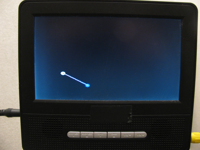
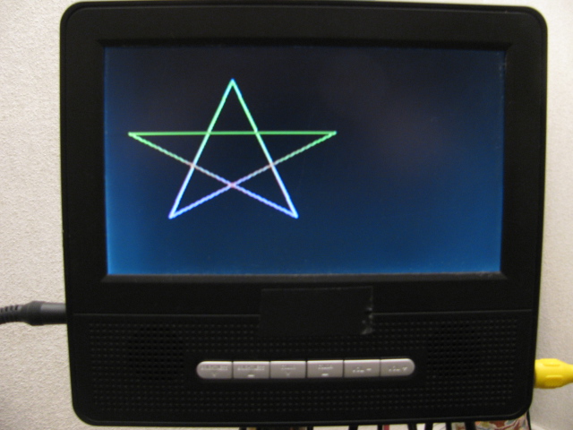
The code idea came after reading a Wiki article :- http://en.wikipedia.org/wiki/Bresenham%27s_line_algorithm
It was almost a cut and paste deal.....with tweaking to convert to Spin code.
This is a basic way to move an xy plotter - laser cutter - cnc from point to point......
The code that follows below draws a simple "dot to dot" straight line to a TV display (tnx Chip Gracey) .
I will be using this "dot to dot" approach to send steps to my stepper motors...
I hope this code helps anyone searching a start into XY plotting physical devises.
Program :-
Update 20130120 :-
Slimlined call routine.....( & removed annoying "quit" from loop command tsktsktsk)
Update 20130122 :-
From theory into practise.
Mechanics and resulting software generated lines .
(albeit plauged with backlash from cheap etchAsketch...however you can see its leaning in the right direction)
![IMG_0952[1].JPG](https://forums.parallax.com/uploads/attachments/63065/95666.jpg)
![IMG_0953[1].JPG](https://forums.parallax.com/uploads/attachments/63065/95667.jpg)
Data set for the 16 magic lines :-
Update 20130125 :-
Getting to grips with sin and cos :-
LCD screen for theory and >>>>>>>>>>>>>>>>>>>>>>>>>>>>>>>>>>>VVV for EAS reality
Spirals are taking shape.....
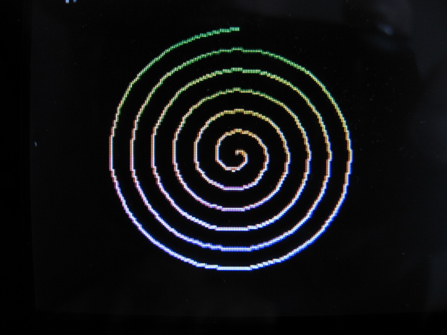
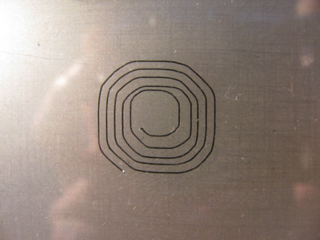
Astute readers will notice a CW - CCW error in my coding.
(not sure if its an error with lcd code or stepper code yet, it will "Iron out" when i start scaling the routines down )
Spiral code (first attempt) :-
Update 20130130 :-
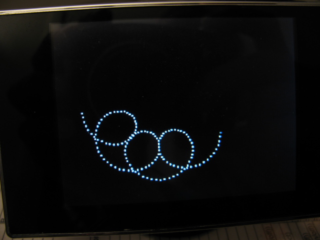
Now plotting epicycloids :-
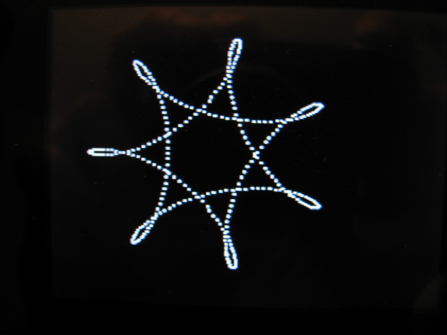
and Hypocycloids :-
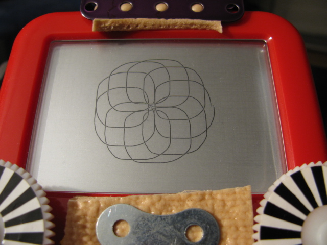
And Etch-A-Sketch driven by the code :-
Why do i use and need drawing routines......
Well...... its not only the start and stop coordinates i am interested in....... i need to know also the "In-betweens" for stepper motor control.
also :- calculating 360 points for a circle (with sin cos ) can be very time consuming ..when you could do it instead with 36 points and just join the dot2dots.
(and drive my mini etch-a-sketch board)
Goal :-
Get from x1,y1 to x2,y2 ........ a straight line ...... in an efficient way.
Solution :-
Bresenhams line algorithm


The code idea came after reading a Wiki article :- http://en.wikipedia.org/wiki/Bresenham%27s_line_algorithm
It was almost a cut and paste deal.....with tweaking to convert to Spin code.
This is a basic way to move an xy plotter - laser cutter - cnc from point to point......
The code that follows below draws a simple "dot to dot" straight line to a TV display (tnx Chip Gracey) .
I will be using this "dot to dot" approach to send steps to my stepper motors...
I hope this code helps anyone searching a start into XY plotting physical devises.
Program :-
{{ ┌───────────────────────────────────────────┐
│ Bresenham's line algorithm │
│ Plotting a line between points │
│ ie ( x1,y1 - x2,y2 ) │
│ Demo Code : Gareth │
│ aka Youtube :- Chiprobot │
│ Graphics by Chip Gracey (Parallax) │
└───────────────────────────────────────────┘}}
CON
_clkmode = xtal1 + pll16x
_xinfreq = 5_000_000
_stack = ($3000 + $3000 + 100) >> 2 'accomodate display memory and stack
x_tiles = 16
y_tiles = 12
paramcount = 14
bitmap_base = $2000
display_base = $5000
lines = 5
thickness = 2
mode = 1
VAR
long tv_status '0/1/2 = off/visible/invisible read-only
long tv_enable '0/? = off/on write-only
long tv_pins '%ppmmm = pins write-only
long tv_mode '%ccinp = chroma,interlace,ntsc/pal,swap write-only
long tv_screen 'pointer to screen (words) write-only
long tv_colors 'pointer to colors (longs) write-only
long tv_hc 'horizontal cells write-only
long tv_vc 'vertical cells write-only
long tv_hx 'horizontal cell expansion write-only
long tv_vx 'vertical cell expansion write-only
long tv_ho 'horizontal offset write-only
long tv_vo 'vertical offset write-only
long tv_broadcast 'broadcast frequency (Hz) write-only
long tv_auralcog 'aural fm cog write-only
word screen[x_tiles * y_tiles]
long colors[15]
OBJ
tv : "tv.spin" ' by Chip Gracey (Parallax)
gr : "Graphics.spin" ' by Chip Gracey (Parallax)
PUB start | i, j, dx, dy
'*********** GRAPHICS SETUP ********************
'start tv
longmove(@tv_status, @tvparams, paramcount)
tv_screen := @screen
tv_colors := @colors
tv.start(@tv_status)
'init colors
repeat i from 0 to 15
colors[i] := $00001010 * (i+4) & $F + $2B060C02
' 0=black ' 1=Crazy rainbow ' 2=white ' 3=blue 'init tile screen
repeat dx from 0 to tv_hc - 1
repeat dy from 0 to tv_vc - 1
screen[dy * tv_hc + dx] := display_base >> 6 + dy + dx * tv_vc + ((dy & $3F) << 10)
'start and setup graphics
gr.start
gr.setup(16, 12, 0, 0, bitmap_base)
{{ ┌───────────────────────────────────────────────────────────┐
│ Bresenham's line algorithm │
│ Transcribed from :- │
│ http://en.wikipedia.org/wiki/Bresenham%27s_line_algorithm │
└───────────────────────────────────────────────────────────┘ }}
gr.colorwidth(1,1) ' crazy thin rainbow line colour
drawline ( 585,493,124,158)
drawline ( 124, 158,300,700)
drawline ( 300,700,476,158)
drawline ( 476,158,15, 493)
drawline ( 15, 493,585, 493)
pub drawline(x1, y1, x2, y2) | sx,sy,ddx,ddy,err,e2,colour
x1:=x1/4 ' scale the coords to fit screen
x2:=x2/4
y1:=y1/4
y2:=y2/4
ddx := ||(x2-x1) ' "||" = ABS(x2-x1) ie force any negative result to positive
ddy := ||(y2-y1)
if (x1 < x2)
sx := 1
else
sx := -1
if (y1 < y2)
sy := 1
else
sy := -1
err := ddx-ddy
repeat
gr.plot(x1,y1)
gr.copy(display_base)
if ((x1 == x2) AND ( y1 == y2))
quit
e2 := 2*err
if e2 > -ddy
err := err - ddy
x1 := x1 + sx
if e2 < ddx
err := err + ddx
y1 := y1 + sy
DAT
tvparams long 0 'status
long 1 'enable
long %001_0101 'pins caution>>> set up to your graphic pin outputs
long %0000 'mode
long 0 'screen
long 0 'colors
long x_tiles 'hc
long y_tiles 'vc
long 10 'hx
long 1 'vx
long 0 'ho
long 0 'vo
long 0 'broadcast
long 0 'auralcog
{{
┌──────────────────────────────────────────────────────────────────────────────────────────────────────────────────────────────┐
│ TERMS OF USE: MIT License │
├──────────────────────────────────────────────────────────────────────────────────────────────────────────────────────────────┤
│Permission is hereby granted, free of charge, to any person obtaining a copy of this software and associated documentation │
│files (the "Software"), to deal in the Software without restriction, including without limitation the rights to use, copy, │
│modify, merge, publish, distribute, sublicense, and/or sell copies of the Software, and to permit persons to whom the Software│
│is furnished to do so, subject to the following conditions: │
│ │
│The above copyright notice and this permission notice shall be included in all copies or substantial portions of the Software.│
│ │
│THE SOFTWARE IS PROVIDED "AS IS", WITHOUT WARRANTY OF ANY KIND, EXPRESS OR IMPLIED, INCLUDING BUT NOT LIMITED TO THE │
│WARRANTIES OF MERCHANTABILITY, FITNESS FOR A PARTICULAR PURPOSE AND NONINFRINGEMENT. IN NO EVENT SHALL THE AUTHORS OR │
│COPYRIGHT HOLDERS BE LIABLE FOR ANY CLAIM, DAMAGES OR OTHER LIABILITY, WHETHER IN AN ACTION OF CONTRACT, TORT OR OTHERWISE, │
│ARISING FROM, OUT OF OR IN CONNECTION WITH THE SOFTWARE OR THE USE OR OTHER DEALINGS IN THE SOFTWARE. │
└──────────────────────────────────────────────────────────────────────────────────────────────────────────────────────────────┘
}}
Update 20130120 :-
Slimlined call routine.....( & removed annoying "quit" from loop command tsktsktsk)
{{  ┌───────────────────────────────────────────────────────────┐
    │              Bresenham's line algorithm                   │
    │                  Transcribed from :-                      │
    │ http://en.wikipedia.org/wiki/Bresenham%27s_line_algorithm │
    └───────────────────────────────────────────────────────────┘ }}


  gr.colorwidth(1,1)     ' crazy thin rainbow line colour

  drawline (112,100, 25, 50)
  drawline ( 25, 50, 62,125)
  drawline ( 62,125,100, 50)
  drawline (100, 50, 12,100)
  drawline ( 12,100,112,100)


pub drawline(x1, y1, x2, y2) | sx,sy,ddx,ddy,err,e2

  ddx := ||(x2-x1)       '  "||" = ABS(x2-x1)  ie force any negative result to positive
  ddy := ||(y2-y1)
  err := ddx-ddy

       sx := -1
   if (x1 < x2)
       sx := 1

       sy := -1
   if (y1 < y2)
       sy := 1

   repeat until ((x1 == x2) AND ( y1 == y2))  '  origin has wandered to its goal YAY...better stop
      gr.plot(x1,y1)
      gr.copy(display_base)

      e2 := 2*err

       if e2 > -ddy
         err := err - ddy
         x1 := x1 + sx

       if e2 < ddx
         err := err + ddx
         y1 := y1 + sy
Update 20130122 :-
From theory into practise.
Mechanics and resulting software generated lines .
(albeit plauged with backlash from cheap etchAsketch...however you can see its leaning in the right direction)
![IMG_0952[1].JPG](https://forums.parallax.com/uploads/attachments/63065/95666.jpg)
![IMG_0953[1].JPG](https://forums.parallax.com/uploads/attachments/63065/95667.jpg)
Data set for the 16 magic lines :-
'  U=Up  D=Down R=Right L=Left        RL=draw line from Right to Left
' the 1,0,-1 are for my reference and i have used them to filter the steppers up down right left movements.
drawline (0,0,0,250)  ' -1  1  0 -1                line U
drawline (0,250,0,0)  ' -1 -1  0 -1                line D
drawline (250,0,0,0)  ' -1 -1 -1  0                line RL
drawline (0,0,250,0)  '  1 -1 -1  0                line LR
drawline (0,0,250,250)'  1  1 -1 -1                line UR
drawline (250,250,0,0)' -1 -1 -1 -1                line DL
drawline (0,250,250,0)'  1 -1 -1 -1                line DR
drawline (250,0,0,250)' -1  1 -1 -1                line UL
drawline (0,0,100,300)'  1  1 -1 -1    1  1  0 -1  line UR steep
drawline (100,300,0,0)' -1 -1 -1 -1   -1 -1  0 -1  line DL steep
drawline (0,300,100,0)'  1 -1 -1 -1    1 -1  0 -1  line DR steep
drawline (100,0,0,300)' -1  1 -1 -1   -1  1  0 -1  line UL steep
drawline (0,0,300,100)'  1  1 -1  0    1  1 -1 -1  line UR shallow
drawline (300,100,0,0)' -1 -1 -1 -1   -1 -1 -1  0  line DL shallow
drawline (300,0,0,100)' -1  1 -1  0   -1  1 -1 -1  line UL shallow
drawline (0,100,300,0)'  1 -1 -1 -1    1 -1 -1  0  line DR shallow
Update 20130125 :-
Getting to grips with sin and cos :-
LCD screen for theory and >>>>>>>>>>>>>>>>>>>>>>>>>>>>>>>>>>>VVV for EAS reality
Spirals are taking shape.....


Astute readers will notice a CW - CCW error in my coding.
(not sure if its an error with lcd code or stepper code yet, it will "Iron out" when i start scaling the routines down )
Spiral code (first attempt) :-
circles := 10      'starting spiral size
 repeat Steps from -180 to 180  step 1 ' Integer PI step values ie choose 360 points
      xx2:= 500+f32.FTrunc(fx)     ' this preserves the old X,Y end plot ... to be then used as origin of the next new line.
      yy2:= 400+f32.FTrunc(fy)

      fx := f32.FFloat( Steps )        '  convert integer Pie (numnumnum) to FloatingPoint Pie
      circleFloat := f32.FFloat(circles) '  convert integer circle to FloatingPoint circle
      fy := fx                       '  duplicate value for Cos bit
      fx := f32.FMul( fx, constant( pi / 30.0 ) )     ' Scale to actual PI values
      fx := f32.FMul( f32.sin( fx ), circleFloat )     ' calculate Sin(fx)* circle size

      fy := f32.FMul( fy, constant( pi / 30.0 ) )     ' Scale to actual PI values
      fy := f32.FMul( f32.cos( fy ), circleFloat )     ' calculate Cos(fy)* circle size
         xx1:=500+f32.FTrunc(fx)
         yy1:=400+f32.FTrunc(fy)

      drawline(xx1/5,yy1/5,xx2/5,yy2/5)
    circles++
Update 20130130 :-
Now plotting epicycloids :-

and Hypocycloids :-

And Etch-A-Sketch driven by the code :-

Why do i use and need drawing routines......
Well...... its not only the start and stop coordinates i am interested in....... i need to know also the "In-betweens" for stepper motor control.
also :- calculating 360 points for a circle (with sin cos ) can be very time consuming ..when you could do it instead with 36 points and just join the dot2dots.


Comments
-Phil
My first idea is just to send the step pulses direct from the algorithm to allow for straight line , it should work (not forgetting i have to work out the orientation of robot to get to next waypoint).... there still much "to do"
The class of algorithms like Bressenhams are know as DDA (digital differential analysers - named by analogy (!) with analog computers I believe).
The basic trick is also know as coherence - any calculation that is done repetitively using a step variable can be reduced in order. Thus in BLA
each step to the next line only involves addition/subtraction instead of multiplication or division as the naive geometric approach would use.
Similarly Bressenham's circle algorithm replaces square-root calculations with 2 addition/subtractions as you step from one point to the next.
Consider the pseudo-code
  for i = 0 to 10
    print i * 7
You can replace this byproduct = 0 for i = 0 to 10 print product product = product+7 // an addition here maintains the product without having to multiplyAnother way to think of this is to express the higher order operation recursively: And as you step the variable you compute the (say) square in lock-step using the recursive relation - typically extra state has to be maintained.
What i have noticed with this methode is that no artifacts (holes in the line) appear ... its one continous flow....the next pixel is always adjacent.
.... here is just some screen test outputs which will be confirmed with and Etch-A-Sketch pad driven by stepper.
There appears to be only 14 combinations to draw a connecting dot2dot line......
Heck, everything works in a simulation! Robotics is real-world with all it's ugly little singularities, but you know that, Gareth!
Please dont ask me to explain this yet .... it took me all evening and it does give me XY forward/reverse step instructions for both steppers :-
The Magic 14 (i hope only 14) ways to draw continuous dot2dot lines.
drawline (0,0,0,50) ' -1 1 0 -1
drawline (50,0,0,0) ' -1 -1 -1 0
drawline (0,0,50,0) ' 1 -1 -1 0
drawline (0,50,0,0) ' -1 -1 0 -1
drawline (0,0,50,50) ' 1 1 -1 -1
drawline (50,50,0,0) ' -1 -1 -1 -1
drawline (0,50,50,0) ' 1 -1 -1 -1
drawline (50,0,0,50) ' -1 1 -1 -1
drawline (0,0,60,90) ' 1 1 -1 -1 & 1 1 0 -1
drawline (60,90,0,0) ' -1 -1 -1 -1 & -1 -1 0 -1
drawline (0,90,60,0) ' 1 -1 -1 -1 & 1 -1 0 -1
drawline (60,0,0,90) ' -1 1 -1 -1 & -1 1 0 -1
drawline (0,0,90,60) ' 1 1 -1 0 & 1 1 -1 -1
drawline (90,0,0,60) ' -1 1 -1 0 & -1 1 -1 -1
They are programmed in however i cant see any patterns in the data to create a simple formular from the above data.....(it is there ... i just cant see it)
The first observation is that the sign of each step can be factored out at the start - for a given straight line segment
the sign of the steps in x and y can be recorded at the start, and the x and y deltas made all positive.
Then during the loop you progress the major axis every time and the minor axis whenever the test succeeds, so
the cases are
step major only
step major and minor together.
So 2 cases
[SIZE=1][FONT=courier new]'this if for first octant only.
PUB MakeLineSteps(x0,y0,x1,y1) : ya | xp,yp,dx,dy
  xp := x0   ' points xp and yp will be visited
  yp := y0
  dx := x1 - x0     ' dy / dx is the slope of the line
  dy := y1 - y0
  repeat dx+1     ' number of steps is known in advance
     plot(xp,yp)   ' this not shown plots each point
     xp++                ' step right by one
     ya += dy    ' the accumulation
     if ya => dx        ' modulo dx
       ya -= dx
       yp++              ' if overflow, step up by one[/FONT][/SIZE]
In the first octant, the slope of the line is the ratio of two positive integers dy / dx, with dx>dy. There are a total of dx steps to the right, and dy steps up. At each step to the right, the algorithm adds dy to an accumulator. If the accumulator is less than dx, then do not take a step up. If the accumulator is greater than or equal to dx, then take a step up and subtract dx from the accumulator.It needs a wrapper for the other 7 octants. I didn't try to work that out, but it would be similar to the Bresenham wrapper.
The wrapper is implemented now in lineAlgorithm3.spin
adx = abs(dx) * MAX_VELOCITY
ady = abs(dy) * MAX_VELOCITY
sdx = sign(dx)             'Sign is -1, 0 or +1.
sdy = sign(dy)
px = ady / 2
py = adx / 2
while dx or dy
  delay(dt)
  px = px + veloc
  py = py + veloc
  if (px >= ady) then
    px = px - ady
    step (x, sdx)
    dx = dx - sdx
  if (py >= adx) then
    py = py - adx
    step (y, sdy)
    dy = dy - sdy
This is a very-much stripped-down version, but it gives the flavor of the dynamics involved. The variable veloc can be varied during the course of the movement to accommodate ramping. It should always be less than or equal to MAX_VELOCITY.
-Phil
-Phil
A sign method is pretty simple to write:
This works because conditionals, when true, return -1.
-Phil
Here are the nuts and bolts of the first stage........
The magic 16 lines ........ however there is some backlash on my "etch a sketch" ....(i have a way to eliminate it though ..stay tuned)
17 boxes drawn in a loop.
There is some rounding of the corners.......i have to tweak the software deadband control.
Bottom left is the origin ..... you can see an issue with the aluminium powder clogging up.
So if you take the axel direction that is the longest and make that speed: 1.0 (max stepper speed)
And the shorter get it's value to be calculated to be 0.246 etc, that you use for it's accumulator.
If you keep adding to the counters, both will move close to a analog fashion and they should end up at the end position at the same time.
Im a missing something?
Well if you ignore friction, non-uniform machining of motor pole step-grooves, eccentric alignment of axle, electrical
phase difference between A and B not being exactly 90 electrical degrees, non-perfect matching of drive currents in the
two windings, then yes, unlimited precision
http://hektor.ch/Videos/
Heres my first attempt at Circles......
Now with Formula driven code...
fx := f32.FMul( f32.sin( fx ), circleFloat ) ' calculate Sin(fx)* circle size
fx := f32.FMul( fx, constant( pi / 180.0 ) )
fy := f32.FMul( f32.cos( fy ), circleFloat ) ' calculate Cos(fy)* circle size
fy := f32.FMul( fy, constant( pi / 180.0 ) )
Would it qualify for entry into your "Oval" challenge if i squash them a tad .
You know tonyp12, what you are describing is also lingering in my cortex and somehow, some way, this is what i sincerely hope will happen. (just as soon as I transfer the coding to a propeller stepper enabled robi)
Plan B is to devise (a dead reckoning compass) deal (its another long shot)..
Throw a sun dial on that EAS and put it in a museum!
fx := f32.FMul( fx, constant( pi / 45.0 ) ) ' Scale to actual PI values
fx := f32.FMul( f32.sin( fx ), circleFloat ) ' calculate Sin(fx)* circle size
fy := f32.FMul( fy, constant( pi / 180.0 ) ) ' Scale to actual PI values
fy := f32.FMul( f32.cos( fy ), circleFloat ) ' calculate Cos(fy)* circle size