

QuadX - my latest Propeller with Propellers
 JasonDorie
Posts: 1,930
JasonDorie
Posts: 1,930
This is a project I've been working on for some time, and it's gotten to a point where I think the code is mature enough to release.
I'm including two things here : The code for the quad itself and the executable and source for the configuration program.
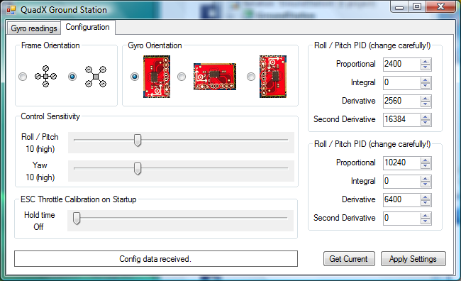
The quad code supports flying in a + or X configuration, as well as a couple different mounting options for the gyro. My quad uses the X configuration, and has the gyro rotated 90 degrees counter-clockwise. If you are going to use a different setup, you'll need to change the configuration appropriately, either in the code, or using the config program. Please note that I have done basically NO TESTING of anything but my own frame setup. I'm working on building a new frame so I can do so, but haven't yet. Whether you use the same setup as me or not, you should do some very basic tests before attempting to fly to ensure that the four motors respond appropriately to flight stick input.
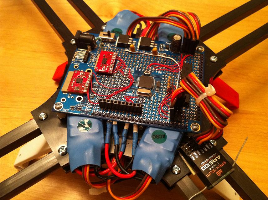
I do not have a schematic, however the amount of soldering involved is very minimal. I use a single Propeller ProtoBoard, an ITG-3200 gyro breakout from SparkFun, eight 3-pin headers to connect the remote receiver and ESCs to, and four 10k resistors between the receiver and the Prop. All the pin numbers are documented at the top of the main SPIN file.
Note that this quad is NOT self leveling or self hovering. It flies like a helicopter, albeit a very stable one. If you have never flown an R/C helicopter before, find someone who has, or practice in a large, flat, grassy area like a soccer field. Do not try to fly it in your living room, garage, driveway, or anywhere near people or things.
Edit: I have added the new Servo8Fast.spin object that allows arbitrary pin assignments, and control of both fast (250hz) and slow (50hz) outputs from a single driver. It is not currently used by the QuadX code, but will be in a future update.

I'm including two things here : The code for the quad itself and the executable and source for the configuration program.
The quad code supports flying in a + or X configuration, as well as a couple different mounting options for the gyro. My quad uses the X configuration, and has the gyro rotated 90 degrees counter-clockwise. If you are going to use a different setup, you'll need to change the configuration appropriately, either in the code, or using the config program. Please note that I have done basically NO TESTING of anything but my own frame setup. I'm working on building a new frame so I can do so, but haven't yet. Whether you use the same setup as me or not, you should do some very basic tests before attempting to fly to ensure that the four motors respond appropriately to flight stick input.
I do not have a schematic, however the amount of soldering involved is very minimal. I use a single Propeller ProtoBoard, an ITG-3200 gyro breakout from SparkFun, eight 3-pin headers to connect the remote receiver and ESCs to, and four 10k resistors between the receiver and the Prop. All the pin numbers are documented at the top of the main SPIN file.
Note that this quad is NOT self leveling or self hovering. It flies like a helicopter, albeit a very stable one. If you have never flown an R/C helicopter before, find someone who has, or practice in a large, flat, grassy area like a soccer field. Do not try to fly it in your living room, garage, driveway, or anywhere near people or things.
Edit: I have added the new Servo8Fast.spin object that allows arbitrary pin assignments, and control of both fast (250hz) and slow (50hz) outputs from a single driver. It is not currently used by the QuadX code, but will be in a future update.

Comments
Used to pass through Bakersfield on my way to visit my parents in Modesto until I moved to TX.
I received both the ITG3200 and the ADXL-345 from Sparkfun this week. I have ordered a Gadget Gangster Propeller Platform USB and the ProtoPlus board to act as a shield for the sensors and Receiver/ESC connections. The rectangular shape of the Propeller Platform will fit better in my Rad Rotary quad than the Parallax Propeller Protoboard which presently has an Arduino Uno and an Aeroquad v 1.6 Shield.
Regards,
TCIII
Your QuadX spin code is missing the following code: Basic_I2C_Driver. This driver is not in the Propeller Library and is not in your spin code file. Do you still intend to use this Driver written by Mike Green in 2007 or update to one of the newer drivers?
Regards,
TCIII
Basic_I2C_Driver.spin
Your latest QuadX code compiles correctly when the Basic_I2C_Driver object is added to the library. However, when I load the compiled code, I get nothing but garbage coming back to the Propeller Terminal. I fell back to your code from around October 2011 and even though it is kind of bare bones, I found that I am getting output from the Gyro and it changes as I move the Gyro around in P/R/Y. Something is happening with the latest code that causes it to output garbage.
Regards,
TCIII
Thanks for the info. Much appreciated. I changed the Propeller code baud rate to 406800, detached my FTDI cable and began to receive Gyro data. However, the communication seems to be only one way. I can receive Gyro data, but the Get Current and Apply Settings buttons do not seem to work. Regards,
TCIII
Tom - I re-uploaded the QuadX package and made sure all the comm speeds were set to 115,200, and that my quad was sending valid data to the ground station when flashed with this code. I also included the missing Basic_I2C driver.
The updated Ground Station code works great as it is smoother and is able to update the EEPROM settings. Much appreciated.
I will implement the Gyro configuration changes per your email suggestion. Might get it work after all.
Regards,
TCIII
It looks like my Sparkfun ITG-3200 Gyro is toast. It would never give a stable output when used with my Parallax Propeller even when level. I attached it to an Arduino Nano and used the demo code supplied by Sparkfun to confirm the state of the Gryo.
The demo program displayed the following raw data rates for the X, Y, and Z axed: -63,~ 4, and ~5 when level. However, when I moved the Gyro in any axis, no matter what direction about the axis, the readings went all over the place indicating a defective Gyro. I always use a static safe work station with grounding strap and a grounded tip Weller solder station so how the part became damaged is a mystery. Word to the wise here: Be as careful as possible with this Gyro as it seems that it can be easily damaged even with proper safegards. I cannot return it to Sparkfun since I added the two pull-up resistors to the board. It might be best to use off-board pull-up resistors incase you have a defective Gyro and then you can return it for a replacement.
Regards,
TCIII
as you do I am using a Gadget Gangster Propeller Platform USB and the ProtoPlus to test parts of Jason program.
ITG3200 and ADXL345 seem to work and also give results with the DCM program and visualizer.
For the moment it is only tests on a stand before trying to fly.
Jean Paul
I think that I received a damaged ITG3200 from Sparkfun as it just would not give stable readings when level nor when tilted in any axis. The test with the Arduino Nano confirms that it would give a quasi stable reading when level, but the readings were random +/- values when tilted in any axis. I have another ITG3200 Gyro from Aeroquad on one of their Shield boards and it works fine. I might take the Gyro to work and check it under a microscope to make sure the pullup resistors are soldered on correctly. However I initially used off board pullups and the Gyro acted the same way as with the onboard pullups. This is not the first time that I have had a defective product from Sparkfun that I could not return for a replacement. I must say that Jason was most helpful with the troubleshooting and went out of his way over the Christmas holidays to help me troubleshoot the Gyro.
Regards,
TCIII
I was using Jason's Ground Station application and the readings were going all over the place when I tilted the Gyro on the Gadget Gangster Propeller Platform USB. I have another ITG3200 mounted on an Aeroquad Shield board and it correctly outputs raw gyro data when tilted about all three axes. I used the Sparkfun Arduino code with an Arduino Nano to confirm the operation of the Gyro.Parallax will not allow the .pde file to be uploaded. However here is a link to the application on the Sparkfun website: http://www.sparkfun.com/tutorials/265
Someone had messed with the code and inserted Degrees where the raw data should have been. Once I corrected that error, I was able to receive raw data from the Gyro. The Sparkfun app basically sets the Gyro up per the Inversense application instructions. I was able to get a stable raw data reading of X: -63, Y: 5, Z: 8 when the Gyro was level. But when I rotated it about any of the axes, no matter what direction I moved in, I would get wild +/- raw data outputs indicating a defective Gyro.
Regards,
TCIII
I reworked the pullup resistors on the Gyro and checked it out again on my Arduino Nano. As you indicate, the readings are very stable at rest, go wild when moved, and then restabilize when at rest again. On the Nano, the at rest values are very stable varying only +/- a couple of raw units. I wish that I could say the same about when the Gyro is attached to the Propeller. Since I reworked the pullups, the readings on Jason's Ground Station look better than before, but are still quite noisy and do not converge anywhere near zero for each axes at rest like Jason's values above. Very strange to say the least.
Regards,
TCIII
Edit: Loaded proper file.
The Gyro is still during the first two seconds or more per your instructions. The Gyro is laying on a flat surface during start up. It is laying on the same flat surface whether I am testing with the Arduino Nano or the Gadget Gangster Propeller Platform USB.
Regards,
TCIII
Thanks for the modified code. I will give it a try shortly.
That did the trick Dave. Much appreicated. I have not looked at your modified code yet, but it will be interesting to understand what modifications you made to Jason's ITG-3200-pasm.spin code to get it to work so well. In my case, it looks like I need the accelerometer input to provide stable Gyro output. I wonder why my setup will not give stable output without the use of the accel? Jason is able to get stable output without the accel. What gives?
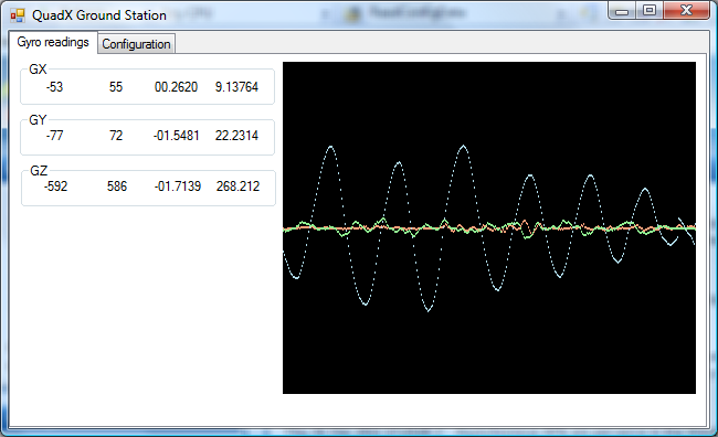
Attached is a screen shot using Dave's ITG-3200-pasm-mod.spin code while the second screen shot shows Jason's original ITG-3200-pasm.spin code.
Regards,
TCIII
So the modified code that you directed me to still only uses just the Gyro and no Accel, right? I guess that the missing NAK fix worked for me which is demonstrated by the screen shots above. Thanks for the help. Now on to incorporating the Accel input.
Regards,
TCIII
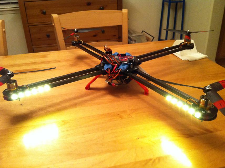
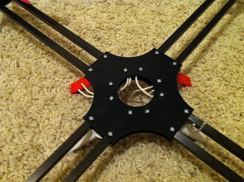
I've attached a few pics - I'm quite happy with how it turned out.
The missing NAK & i2cStop calls are supposed to be there. The QuadX code currently only uses the gyro, but the ITG/ADXL driver is shared between that code and a version I'm working on that includes self-leveling. That code actually works, and is quite stable, but before I had a chance to finish tuning and cleaning it up I had a crash that wrote off my board (hence the previous post with my new frame). Once I have a platform with a gyro & accel combo up & running again, I can finish up the full stability code.
(dont like to connect Propeller or Radio on the motors lipo battery BEC)
But dont know how many mAh this receiver use ?
Any idea ?
Jean Paul