

PropTouch Propeller Platform Handheld Kit
 jazzed
Posts: 11,803
jazzed
Posts: 11,803
I've been working on this design for a while and am getting ready to shoot boards.
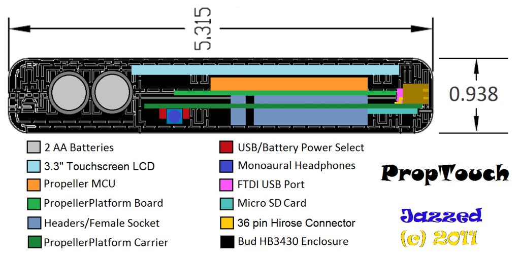
The design uses a Propeller Platform short board for the micro. It is designed for a specific Propeller board, but could easily accept any Propeller Platform short board with a compatible assembly. I may create boards which would include other micros at some point.
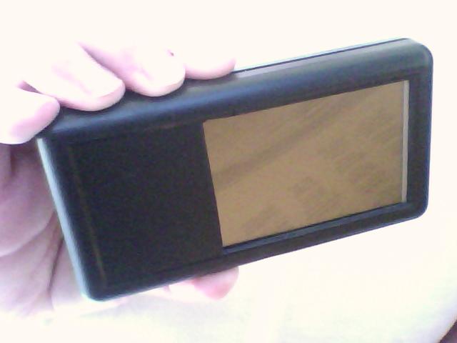
Shown is a package with LCD (262K colors and separate Graphics RAM) in a modified Bud Industries HB3430 enclosure. Depending on interest I will pay to have BUD industries modify the enclosure for a finished look.
The LCD could be replaced with some other Propeller Platform module: that is, you don't have to have an LCD, it could be another board. The LCD with touch-screen is available from Mouser/Digikey. There are other LCDs which could be used with a special Propeller Platform module.
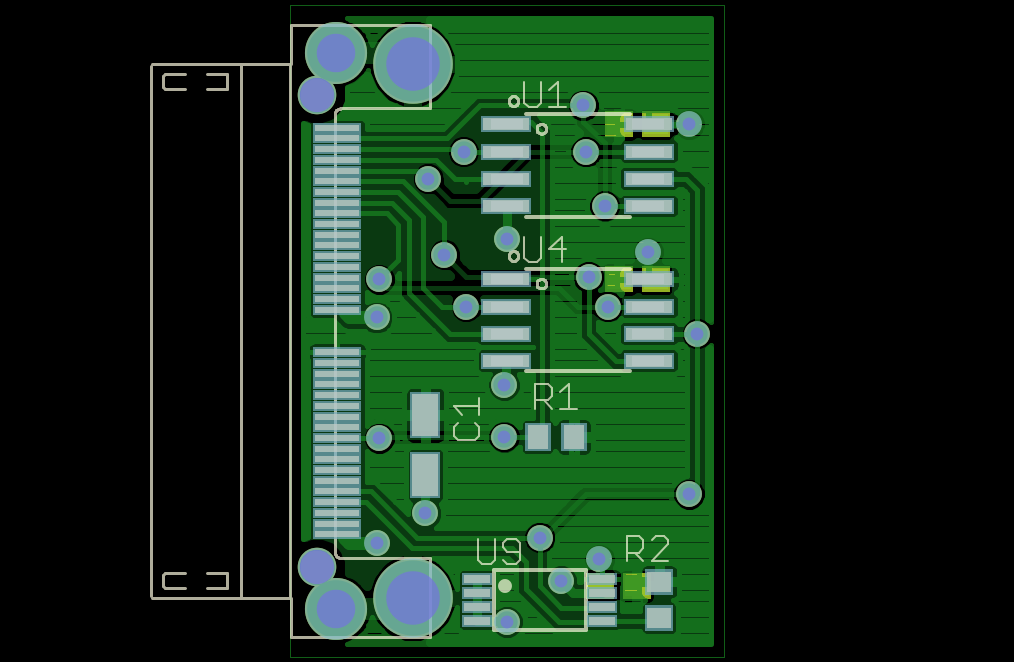
The motherboard has components listed in the Enclosure Stackup as well as footprints for 2 quad-SPI Flash chips (fast access and non-volatile storage). I expect that the Flash chips could be programmed with code or data taken from the SD card and 262K color mode on LCD. Catalina, PropellerJVM, or other language such as XBASIC (when ready) that can fetch/execute code from external memory would benefit from speedup provided by this temporary storage. An optional SRAM module can be used with 65K color mode on the LCD (number of colors available depends on the number of propeller pins in use).
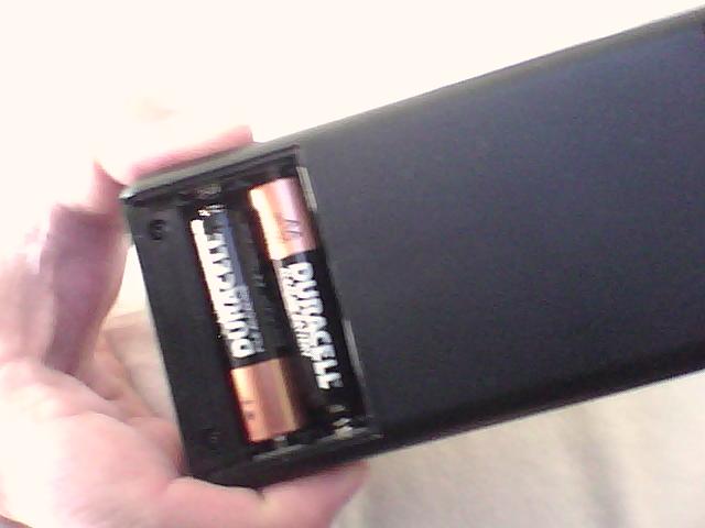
The motherboard has a switch that lets you select USB or AA battery power. A jumper on the motherboard will allow using power provided by a Propeller Platform board if necessary.
There is room for a small 4 button membrane switch below the LCD.
I'm hoping to have kits for this and SpinSocket32 modules available for UPEW.
If you are interested in this project, please comment. If there is no interest, it will go on the shelf.
I'll have a prototype to show at UPEW, but it would also be useful to know how many kits i should make. The assembled boards will be fairly cheap as is the enclosure - I have some Propeller Platform boards that fit in the stackup and they will be available for you to add your hardware.

Stackup:

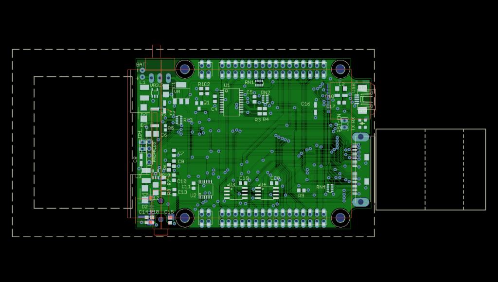
Motherboard module shows outline of enclosure and expansion modules:

Optional Flash/EEPROM module 1.2" x 0.8"

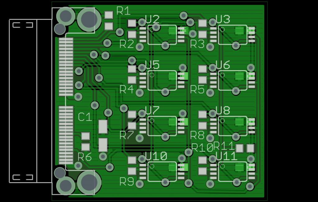
Optional IO Expander module 1.2" x 1.3". Also a compatible connector for cables is available.

Optional SRAM/Flash/EEPROM module 1.2" x 1.7":

Here is a picture of the cable connector shell for expansion ports. I may be able to squeeze a Flash cartridge into one ... we'll see.
.JPG)
Also attached but not shown in line is picture of a 1.2" x 1.3" SRAM module.
The design uses a Propeller Platform short board for the micro. It is designed for a specific Propeller board, but could easily accept any Propeller Platform short board with a compatible assembly. I may create boards which would include other micros at some point.
Shown is a package with LCD (262K colors and separate Graphics RAM) in a modified Bud Industries HB3430 enclosure. Depending on interest I will pay to have BUD industries modify the enclosure for a finished look.
The LCD could be replaced with some other Propeller Platform module: that is, you don't have to have an LCD, it could be another board. The LCD with touch-screen is available from Mouser/Digikey. There are other LCDs which could be used with a special Propeller Platform module.
The motherboard has components listed in the Enclosure Stackup as well as footprints for 2 quad-SPI Flash chips (fast access and non-volatile storage). I expect that the Flash chips could be programmed with code or data taken from the SD card and 262K color mode on LCD. Catalina, PropellerJVM, or other language such as XBASIC (when ready) that can fetch/execute code from external memory would benefit from speedup provided by this temporary storage. An optional SRAM module can be used with 65K color mode on the LCD (number of colors available depends on the number of propeller pins in use).
The motherboard has a switch that lets you select USB or AA battery power. A jumper on the motherboard will allow using power provided by a Propeller Platform board if necessary.
There is room for a small 4 button membrane switch below the LCD.
I'm hoping to have kits for this and SpinSocket32 modules available for UPEW.
If you are interested in this project, please comment. If there is no interest, it will go on the shelf.
I'll have a prototype to show at UPEW, but it would also be useful to know how many kits i should make. The assembled boards will be fairly cheap as is the enclosure - I have some Propeller Platform boards that fit in the stackup and they will be available for you to add your hardware.
Stackup:
Motherboard module shows outline of enclosure and expansion modules:
Optional Flash/EEPROM module 1.2" x 0.8"
Optional IO Expander module 1.2" x 1.3". Also a compatible connector for cables is available.
Optional SRAM/Flash/EEPROM module 1.2" x 1.7":
Here is a picture of the cable connector shell for expansion ports. I may be able to squeeze a Flash cartridge into one ... we'll see.
Also attached but not shown in line is picture of a 1.2" x 1.3" SRAM module.
640 x 480 - 22K
640 x 480 - 24K
1024 x 513 - 77K
1024 x 580 - 65K
1014 x 662 - 76K
1024 x 651 - 93K
1024 x 580 - 80K
1024 x 621 - 102K
Comments
My hat is off to you for using an existing design (The Propeller Platform Board) and incorporating it into your work! This earns you ***** stars from this direction!
Would you mind doing a detailed submission to Propellerpowered.com?
OBC
@OBC. I see a submit a new project page on PropellerPowered.com. Can I edit the entry if necessary?
'Looks like an elegant design: well-conceived and nicely executed! Congrats!
-Phil
Thanks Phil. Wish me luck finishing this before UPEW.
So, to recap the operational modes and Cartridge "cart" pin availability, you can have:
- Motherboard only with SD card (no LCD, headphones, on-board Flash): 24 free cart pins.
- Motherboard with SD card and SPI LCD (no headphones or on-board Flash): 19 free cart pins.
- Motherboard only with SD card and on-board Flash (no LCD or headphones): 14 free cart pins.
- Motherboard only with SD card, on-board Flash, headphone connected, (no LCD): 13 free cart pins.
- Motherboard with all features and SPI (slow) 262K color LCD: 7 free cart pins.
- Motherboard with all features and Parallel 262K color LCD: no free cart pins.
- Motherboard with all features and Parallel 65K color LCD: no free cart pins, up to 256KB fast SPI SRAM.
The optional onboard flash is 2MB fast access byte wide quad-SPI similar to SpinSocket-Flash and Rayman's FlashPoint. I forgot to mention the LCD has it's own Graphics RAM, so Propeller HUB RAM is available for your application.One of the configurations above should allow a cart with X-bee or some other interfaces.
If I had room for a gyro and an accelerometer on the motherboard I would include it.
As it stands now, a gyro/accelerometer cart is a good expansion candidate.
This rocks! I'd be interested in a #2
I won't be at UPEW, but I am planning on UPEC
Any ballpark on price?
Would be pretty in other colors too.
I keep scouring ebay for cheap LCDs in cases the right
size to be useful for uC projects... I found some small
picture viewers but they were just too tiny to fit much inside.
Plus none had touch screens.
@Holly, try this in the attachment. It's the Varitronix 1.72" SPI LCD with touch screen in an HB3641 case, I plan to make a Propeller PCB for this too (separate power or Lipo battery/charger). A pair would make nice set of "digital eyes" for robot expressions.
I see what you mean about the eyes thing.
That would work very well.
I bet if we just knew the right people in China to talk to we
could get large runs of something like this at a bargain price.
I have been building up a list of salesmen and tech people
in China for 2 years now and it is starting to pay off. I get
at least one email a week with some kind of great offer.
Thanks to everyone for all the input and kind words. Several boards are on order and I should have the motherboard for testing within a week.
rocketbrand at gmail dot com
I think Walter the Robot just got his new control panel and I got a new palm pilot.
So all I did was go to Bud Industries and browse their enclosures... Well, then I had to do the usual round of mouser and sparkfun and 4D systems and look at LCD's. Here it is 4 hours later, I have 20 sketches on napkins, 13 (potential) parts lists and you have officially created a monster. I think I might just have to make one of these bad boys myself! Small joystick, x-bee, bluetooth. Tax return is coming in... Kari wants an iPad... Leaves me an opening to order parts...
I GOTTA START DESIGNING SOME PCBS!!
Yup, you have officially created a monster... Such a cool idea and project. Maybe we should all make our own version and have some kinda show and tell later!
http://www.mouser.com/Search/ProductDetail.aspx?R=254TA103B50Avirtualkey67110000virtualkey774-254TA103B50A
The one I got is pretty stiff. The version with the longer actuator is probably better.
I have to say that I've bought many enclosures looking for the right thing on this project.
Finding the right LCD/enclosure combo is difficult.
Hmm...nice.
Here's a status update for anyone following along.
Got 2 motherboard prototypes yesterday. There are no show stoppers so far.
The power sections are working so far and I can program a Propeller on either USB or battery power.
USB powered VDD is 3.37V with about 20mVpp ripple (small load).
2AA powered VDD is 3.36V with about 8mVpp ripple (small load).
LCD backlight voltage is about 19VDC with similar ripple (no load yet).
I really like the fact that my power switch behaves like a on/off switch when only one type of power is connected. It is also a power source select when both USB and battery are connected. Since the power switch does have an intermediate unconnected state, it also behaves like a reset button
The Propeller Platform board-to-board connector system works but I'll probably change the footprint to require the dual-entry female plugs rather than allowing for the through-hole connectors for manufacturability. It's possible that this is a better stacking solution all around since it would allow boards to have only the the female plugs and be stacked like pancakes with any interboard clearance on un-soldered long male headers - the number of boards stacked depends on how long are the male headers.
I'm impressed with the Hirose ST series connector solution. I'm certain that small dongle cartridges can be made now that I have samples of the cable shell. My footprint on the motherboard works, but needs a little tuning to ensure easy placement. This connector solution is not as cheap as some others, but it allows full access to 32 propeller pins with a spare for LCD parallel bus configuration .
There are some dirty laundry items like small mechanical alignment issues and a few schematic errors, so a respin is required.
More to come ...
--Steve
Quick update.
I got the LCD lit up yesterday and have been doing some preliminary battery life testing with the LCD back-light on. The back-light is by far the highest current consumer in the "system" so if that's not usable, nothing is. Based on *current* results it appears the project remains viable.
Fortunately, my back-light circuit is connected to the LCD PWM output which is configurable. The PWM can be set to suck the most energy of course but that's not recommended at all
(All this data is with the LCD active. That is: the LCD is not in standby/sleep mode. On standby, the LCD is practically not connected.)
With my maximum LCD PWM setting I have been running on 2 fresh Duracell AA batteries for the last 6+ hours and there is still lots of power left relatively speaking. I'll do similar testing with 2 rechargable NiMH AA batteries later.
It should be noted that the power supply/other components pass the "teenager test" - that is, no high pitch squeals are detected
The 2AA batteries lasted 12 hours with the LCD backlight turned continuously on to "maximum" brightness.
Obviously the LCD backlight will not be on continuously on battery power and standby modes take very little energy. A battery monitor is included on the board, so power management could make 2 AA's last a very long time.
Next up: get some pictures on that LCD.