

Homemade single side through hole open board for the Propeller hobbyist
 Jean-Marie
Posts: 128
Jean-Marie
Posts: 128
Hi,
First of all, excuse me for my superficial knowledge of English. Some people think we choose in which family we come into existence. Unfortunately I don't remember why I chose to come in a French speaking one.
A few months ago, I started learning Atmel AVR (Bascom + ASM). I felt a bit limited by using LCD display and switches to interact with the processor. So I started looking for connecting a keyboard and a PC monitor.
Although there are a few AVR solutions like µVGA on the web, I came across the Propeller 2 to 3 months ago and I quickly understood it was THE solution.
I first tried to program a small 'hello world' on a breadboard with the 3 transistors RS232 adapter : http://forums.parallaxinc.com/forums/attach.aspx?a=6685
Now I would like to go a bit further and etch a single side through hole board. Not only to connect a VGA monitor and a keyboard but I have read so many interesting experiments (Zicog, qz80, Ramblade, Propdos, LMM, CP/M, etc…) that I want the board as open as possible. I know it would be easier to buy a Demo board, a Proto board, a Lab board or a Ramblade but I really enjoy making things myself, so buying is not only four times more expensive but also four times less rewarding.
To start with, I was thinking of designing a sort of Demo board with the 40 DIL version, adding 4 x female connector strip with 10 pin each (8 I/O ports + 3.3V + GND). Also possibly adding some dip switches to disconnect TV / VGA and Keyboard / Mouse for compatibility with Hydra board.
I am sure I am not the only one with this idea but I couldn’t find such a homemade board through the whole forum . Could anyone show me a useful link ?
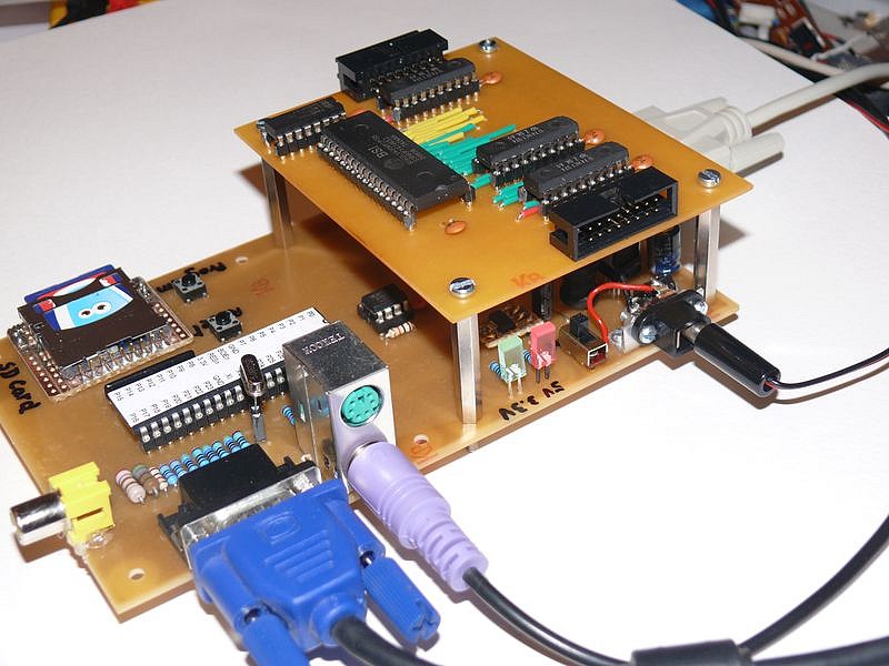
The board evolved to become a homemade Dracblade running KyeDos and CP/M.
See attached picture, schematics and PCB layouts
Jean-Marie
First of all, excuse me for my superficial knowledge of English. Some people think we choose in which family we come into existence. Unfortunately I don't remember why I chose to come in a French speaking one.
A few months ago, I started learning Atmel AVR (Bascom + ASM). I felt a bit limited by using LCD display and switches to interact with the processor. So I started looking for connecting a keyboard and a PC monitor.
Although there are a few AVR solutions like µVGA on the web, I came across the Propeller 2 to 3 months ago and I quickly understood it was THE solution.
I first tried to program a small 'hello world' on a breadboard with the 3 transistors RS232 adapter : http://forums.parallaxinc.com/forums/attach.aspx?a=6685
Now I would like to go a bit further and etch a single side through hole board. Not only to connect a VGA monitor and a keyboard but I have read so many interesting experiments (Zicog, qz80, Ramblade, Propdos, LMM, CP/M, etc…) that I want the board as open as possible. I know it would be easier to buy a Demo board, a Proto board, a Lab board or a Ramblade but I really enjoy making things myself, so buying is not only four times more expensive but also four times less rewarding.
To start with, I was thinking of designing a sort of Demo board with the 40 DIL version, adding 4 x female connector strip with 10 pin each (8 I/O ports + 3.3V + GND). Also possibly adding some dip switches to disconnect TV / VGA and Keyboard / Mouse for compatibility with Hydra board.
I am sure I am not the only one with this idea but I couldn’t find such a homemade board through the whole forum
. Could anyone show me a useful link ?The board evolved to become a homemade Dracblade running KyeDos and CP/M.
See attached picture, schematics and PCB layouts
Jean-Marie
800 x 600 - 121K

Comments
www.leonheller.com/Propeller/
It's got a large prototyping area, but I couldn't be bothered to drill all the holes.
I think I mentioned it in the Projects section, but it was some time ago.
You are welcome to the artwork file, if you want to make your own. I've got another version with the sort of I/O connections you mentioned.
▔▔▔▔▔▔▔▔▔▔▔▔▔▔▔▔▔▔▔▔▔▔▔▔
Leon Heller
Amateur radio callsign: G1HSM
Post Edited (Leon) : 7/24/2010 7:59:53 PM GMT
@Jean-Marie welcome to the forum! There's a lot of good stuff here but the built-in search function is pretty bad. I tend to go to Google and look for stuff with the term "site:forums.parallax.com" in the query. I studied French in secondary school but with time and disuse the only thing I remember how to say today is >>Je ne parle pas le francais.
Bienvenue! There's no need to apologize for your English. It's better than that of many native Anglophones in this forum!
-Phil
Many thanks for your link. I am happy not being the last of the Mohicans struggeling with UV and acid.
Your board has the 4 connectors which is probably the most important feature to stay open. You provided power and GND through the external holes. I am still hesitating to add it to the connectors, and perhaps not only 3.3V but also 5V.
____________________________________________________________________________________________
@ Localroger
Thanks for the search function.
You get 10/10 for your French.
_____________________________________________________________________________________________
@ Phipi
Well, the same 10/10 for you.
And thank you for your (French) words of welcome.
Unfortunately, I am sure I'll not keep getting 10/10 for my English.
▔▔▔▔▔▔▔▔▔▔▔▔▔▔▔▔▔▔▔▔▔▔▔▔
Jean-Marie
gadgetgangster.com/
The boards are cheap, and the propeller platform is open source (mit licensed). So you can access the design to be inspired...
If you start a new design from scratch check the forum sticky threads,
propeller.wikispaces.com/ mainly the hardware section, the discussion about decouping capacitors, and OBC's tutorials.
ucontroller.com/Propeller%20Protoboard%20Designs%20for%20the%20Beginner.pdf
and
www.warrantyvoid.us/tiki-index.php?page=Hardware
Massimo
▔▔▔▔▔▔▔▔▔▔▔▔▔▔▔▔▔▔▔▔▔▔▔▔
Leon Heller
Amateur radio callsign: G1HSM
Nice board! This may well be my next home-PCB board!
Thanks!
OBC
▔▔▔▔▔▔▔▔▔▔▔▔▔▔▔▔▔▔▔▔▔▔▔▔
Propeller Feature Projects: PropellerPowered.com
Visit the: PROPELLERPOWERED SIG forum kindly hosted by Savage Circuits.
If you are doing your own pcb, just ensure you place the xtal close to the prop xtal pins and be sure to place decoupling caps (2 x 0.1uF is good, X7R type ceramic preferred) and a bulk cap (10uF Tantalum is good) close to both sets of power/ground pins and ensure they are directly connected together. You can search the forum for design discussions - use Google Advanced search (see link in my signature)
▔▔▔▔▔▔▔▔▔▔▔▔▔▔▔▔▔▔▔▔▔▔▔▔
Links to other interesting threads:
· Home of the MultiBladeProps: TriBlade,·RamBlade,·SixBlade, website
· Single Board Computer:·3 Propeller ICs·and a·TriBladeProp board (ZiCog Z80 Emulator)
· Prop Tools under Development or Completed (Index)
· Emulators: CPUs Z80 etc; Micros Altair etc;· Terminals·VT100 etc; (Index) ZiCog (Z80) , MoCog (6809)·
· Prop OS: SphinxOS·, PropDos , PropCmd··· Search the Propeller forums·(uses advanced Google search)
My cruising website is: ·www.bluemagic.biz·· MultiBlade Props: www.cluso.bluemagic.biz
That is a really nice, simple board....
Welcome Jean-Marie!
We are glad you are here.
▔▔▔▔▔▔▔▔▔▔▔▔▔▔▔▔▔▔▔▔▔▔▔▔
justasm.blogspot.com/
Homemade is great fun. This board www.smarthome.viviti.com/propeller started on a large protoboard with point to point wiring using wire-wrap wire. I've got lots of blank boards if you want one - $10 for one or $20 for three, and the price includes shipping anywhere in the world. I use sockets and some of the chips have been recycled on many different boards.
But it is more fun to make it yourself!
On that webpage is a schematic. Most of the schematic is borrowed from other standard propeller circuits. You can build it in stages. Maybe start with a large blank protoboard. Build the regulators. Build the propeller plus eeprom plus minimal download circuit (transistor or max232, it does not matter).
Add a keyboard socket plus resistors.
Add a VGA or a TV or both.
Add an sd card - just a socket plus a few resistors.
Then if you really want to, you can add the external ram.
I think Toby did a single side version. It would end up a lot bigger, and I'm not sure how many wire links he had.
The whole board might be complicated, but each section is easy to do.
I did try running this through the autorouter once with single side, but it never got close to a solution.
Veroboard might be another option.
Even use a breadboard/prototype board. They used to be expensive, but they are not much more than a solder board now - you can at least change things quickly on a breadboard.
It is fun to have a basic circuit, and then spend 5 minutes soldering and get something on a VGA display. Then another 5 minutes soldering and a keyboard works. The propeller can be very addictive in this way!
▔▔▔▔▔▔▔▔▔▔▔▔▔▔▔▔▔▔▔▔▔▔▔▔
www.smarthome.viviti.com/propeller
I have made many PCBs using the Toner Transfer Method and hand drilling. I found that the cheapest "Value" photo paper gave the best results, consistantly, but glossy magazine paper can work with a bit more fiddling involved. I tend to enjoy the design and construction more than the eventual programming bits.
I lost a load of my layouts when I formated in haste, but if there were a board that you wanted then I am sure I could get some files to you. I use FreePCB to get the Gerber files which I print out with their surgested ViewMate. I know that it is not the best for laying out or vast libraries, but they are cheap, inexpencive and do not cost much.
▔▔▔▔▔▔▔▔▔▔▔▔▔▔▔▔▔▔▔▔▔▔▔▔
Why did I think a new, more challenging, job was a good idea ??
Thanks to your links, I discover Gadget Gangster and their Platform. I like the idea of modules piling up like Arduino. But probably it isn't so easy to realise with a one side PCB : the pin headers are underneath.
So perhaps the connectors of the SpinStudio Mainboard are more adapted to the (modest) hobbyist.
_________________________________________________________________________________
@ Leon
You remind me a story. A long time ago, I spent a while in New Zealand. One of my professors knew quite a lot of French, but he had learned it from books. Each time he spoke to me in French, I didn't understand him because I was sure he was speaking English. When I was told it was French, it didn't help and most often I had to ask him to "translate" it in English.
__________________________________________________________________________________
@Sylvie369
Congratulations for your effort. As long as you express yourself like the Queen Elisabeth, it shouldn't be necessary to write it in French.
I know that my name sounds like a girl name (although it is definitely masculine in French). Your name sounds feminine. Girls or ladies are not numerous in electronic forums.
___________________________________________________________________________________
@Cluso99
Thanks for the tips.
By the way, thanks for your fantastic job with your Ram to 6 Blades.
___________________________________________________________________________________
@HollyMinkowski
Thanks for your words of welcome.
I saw in your blog that you are interested in the Propeller AND in the AVR. I think I will not forget it.
___________________________________________________________________________________
@Dr_Acula
Your board is certainly as clever as the boards of Cluso. Is it because the Aussie air is stronger than anywhere else ? Is it because you have the opportunity to suck fresh blood from your patients ? I don't know but I have read your site 2 to 3 times in the last weeks and it is not finished. Your prices are also very attractive.
___________________________________________________________________________________
@Toby Seckshund
To make PCB, I usually use a very modest program (called TCI) or sometimes Eagle. I print the design on a transparency with an inkjet printer. Then UV exposure, NaOH to reveal and Cupric Acid + H2O2 to etch. It isn't perfect but still enough for one side PCB and very cheap.
▔▔▔▔▔▔▔▔▔▔▔▔▔▔▔▔▔▔▔▔▔▔▔▔
Jean-Marie
Message Edité (Jean-Marie) : 7/25/2010 9:42:29 PM GMT
▔▔▔▔▔▔▔▔▔▔▔▔▔▔▔▔▔▔▔▔▔▔▔▔
Leon Heller
Amateur radio callsign: G1HSM
Platform board ($10 for PCB) which is double-sided. There are two rows of header holes on each side of the board - you can choose to solder the headers on the top, bottom or one of each. Gadget Gangster also offers a ProtoPlus board (composite video and audio) gadgetgangster.com/find-a-project/56.html?projectnum=254 and a VGA AV module gadgetgangster.com/find-a-project/56.html?projectnum=346.
One word of advice - if you buy the bare Propeller Platform board gadgetgangster.com/find-a-project/56.html?projectnum=168 by itself, I recommend also buying the 3.3V and 5.0V regulators from Gadget Gagster because they're in short supply and the pin arrangement is different from a 7805 or 2940 regulator. You can get the regulator's here gadgetgangster.com/find-a-project?subcat=39
As long as I can, I would rather keep on building my own cards than buy already made ones. So I continue to look for the best solution.
My last idea was to use a 10 inches or 25 cm flat ribbon cable like the one for hard drive ide. That sort of cable has 40 ways in 2 rows of 20. The 40 pin box headers are common, strong and cheap and each time you add or pile up a new module, it isn't difficult to crimp a new female connector along the cable and plug it into the module.
40 way connectors are just a good size. There is room for the 4 x 8 I/O ports, 3.3V, 5V, GND and 5 spare ways for later use.
What do you all think about it ?
▔▔▔▔▔▔▔▔▔▔▔▔▔▔▔▔▔▔▔▔▔▔▔▔
Jean-Marie
Just be careful when crimping. I had contact problems between the cable and the connector.
I see you have understood. But your model is more expansive ... and more explosive
_________________________________________________________________________
Hello Max72
I didn't realise the double row wouldn't fit on a breadboard.
... unless you solder a connector and 2 x 20 pin headers on a small perfboard. This could fit in the middel of a breadboard.
▔▔▔▔▔▔▔▔▔▔▔▔▔▔▔▔▔▔▔▔▔▔▔▔
Jean-Marie
Re crimping your own 10 and 20 pin cables, I put them in a vice.
I think a homebrew board is a great idea. Please keep us updated with photos!
▔▔▔▔▔▔▔▔▔▔▔▔▔▔▔▔▔▔▔▔▔▔▔▔
www.smarthome.viviti.com/propeller
Seen your realizations, your encouragement and support is really meaningful.
Although I am retired, it takes me a lot of time to design and build something, so I am still far from the photo. But it should come...
▔▔▔▔▔▔▔▔▔▔▔▔▔▔▔▔▔▔▔▔▔▔▔▔
Jean-Marie
Some of the "Airwires" are planned, but most are corrections/rethinks.
Most of the ones that actually get used are cased and at work where I am the only one that can do such stuff, the younger ones are just not that way inclined.
I have yet to find a suitable UV source, for PCB experiments. Buying one is against the rules ! (mostly HERS).
Sorry the pics are a bit rough, my camera seems to be dying
▔▔▔▔▔▔▔▔▔▔▔▔▔▔▔▔▔▔▔▔▔▔▔▔
Why did I think a new, more challenging, job was a good idea ??
Post Edited (Toby Seckshund) : 7/28/2010 11:04:56 AM GMT
A sheet of glass sits on the wood strips at the top. I used ordinary fluorescent tube units and ballasts for the UV tubes.
It cost me about £20. There is room for a third tube which would reduce the exposure time. It's 11 minutes with the two tubes.
▔▔▔▔▔▔▔▔▔▔▔▔▔▔▔▔▔▔▔▔▔▔▔▔
Leon Heller
Amateur radio callsign: G1HSM
Post Edited (Leon) : 7/28/2010 11:53:42 AM GMT
I have been wondering how long it would take to expose a board with my arc/tig welder, from a reasonable distance is should give good results, perhaps only if I get desperate.
Graham
▔▔▔▔▔▔▔▔▔▔▔▔▔▔▔▔▔▔▔▔▔▔▔▔
Leon Heller
Amateur radio callsign: G1HSM
I remember somthing about ordinary paper soaked in cooking oil or WD40.
I could use the Sun I suppose, that should only take a few months, here in England.
▔▔▔▔▔▔▔▔▔▔▔▔▔▔▔▔▔▔▔▔▔▔▔▔
Why did I think a new, more challenging, job was a good idea ??
I put the PCB on the table, then a square thick glass on top and I cover it with the sun lamp. My exposure time is 3 minutes.
▔▔▔▔▔▔▔▔▔▔▔▔▔▔▔▔▔▔▔▔▔▔▔▔
Jean-Marie
Post Edited (Jean-Marie) : 7/29/2010 7:22:54 AM GMT
▔▔▔▔▔▔▔▔▔▔▔▔▔▔▔▔▔▔▔▔▔▔▔▔
Why did I think a new, more challenging, job was a good idea ??
▔▔▔▔▔▔▔▔▔▔▔▔▔▔▔▔▔▔▔▔▔▔▔▔
Jean-Marie
This is the first design of a very basic board. It has the double voltage (5V from a PC power unit or from an external AC adapter and 3.3V from LM1086 regulator.
Instead of the USB Propeller Plug, I use the RS232 connexion with 3 transistors and some resistors. This is much cheaper and works perfectly.
The 32K EEPROM is present, as well as the 5 Mhz crystal.
The special feature is the 2 x 20 pin box header soldered at right angle near the edge of the PCB. There is room for the 4 x 8 I/O pins. In the middle, there are 8 spare pins divided into 4 pins for GND, 2 pins for 5V and 2 pins for 3.3V. (I am not sure what to use these spare pins for. Perhaps you have an idea).
Of course, this is a one side PCB, although there are 6 (green) straps.
The overall dimensions are 10 x 8 cm ( = half the Europe PCB size) = 3.9" x 3.15"
▔▔▔▔▔▔▔▔▔▔▔▔▔▔▔▔▔▔▔▔▔▔▔▔
Jean-Marie