

STARTED Testing my RS485 Interface Board, Voltage Issue FIXED! Now for the CODE!
 DavidM
Posts: 640
DavidM
Posts: 640
HI,
Its taken a while to find some time to start building my RS485 Interface Board ( I received a LOT OF ADVICE some time ago in a previous posting, so thanks heaps to all those that helped). I have had the PCB's & all the components sitting here for months.
I have soldered on the PCB the MAIN components to at least test the POWER circuits.
I have the I/O pins set up that go to the prop chip as necessary , (i.e inputs/outputs set Hi or low As required by default) I hope?
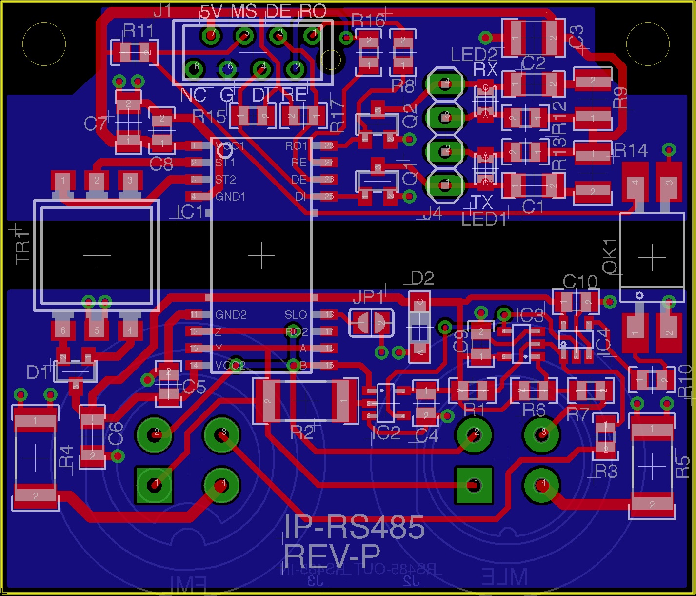
I have attached all relevant docs ( if you wish to help)
So far I have discovered a problem...
(PROBLEM 1)
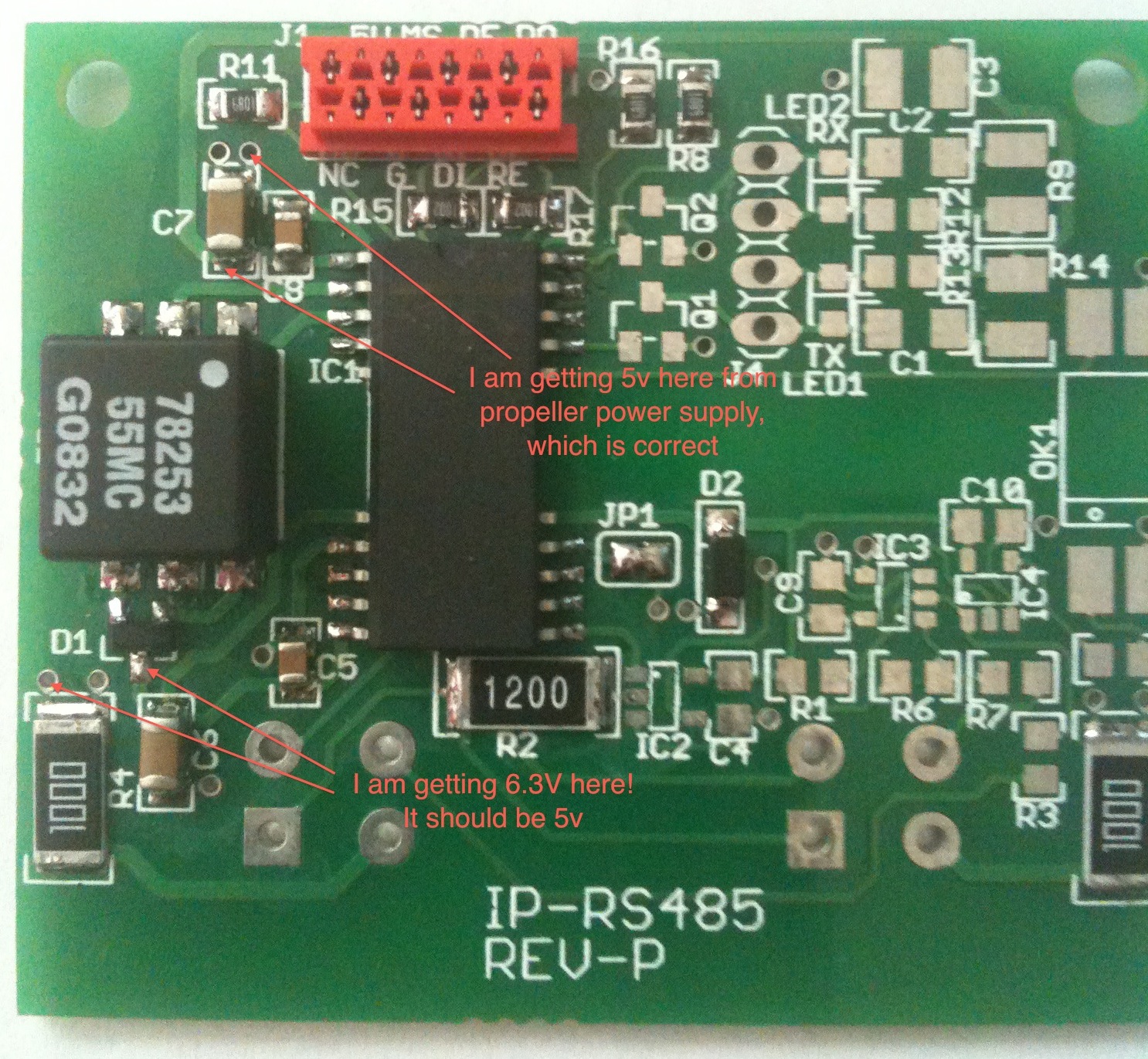
I have 5V coming in from my micro-match header as expected and the IC INPUT SIDE is getting 5V as well, but I am reading 6.16 volts on the output of the Transformer!
(QUESTION 1)
Can any advise why I don't get 5v?
Thanks
Dave M
Post Edited (DavidM) : 2/20/2010 11:35:08 AM GMT
Its taken a while to find some time to start building my RS485 Interface Board ( I received a LOT OF ADVICE some time ago in a previous posting, so thanks heaps to all those that helped). I have had the PCB's & all the components sitting here for months.
I have soldered on the PCB the MAIN components to at least test the POWER circuits.
I have the I/O pins set up that go to the prop chip as necessary , (i.e inputs/outputs set Hi or low As required by default) I hope?
I have attached all relevant docs ( if you wish to help)
So far I have discovered a problem...
(PROBLEM 1)
I have 5V coming in from my micro-match header as expected and the IC INPUT SIDE is getting 5V as well, but I am reading 6.16 volts on the output of the Transformer!
(QUESTION 1)
Can any advise why I don't get 5v?
Thanks
Dave M
Post Edited (DavidM) : 2/20/2010 11:35:08 AM GMT

1427 x 1221 - 554K
1486 x 1371 - 777K
Comments
-Phil
So Are you saying that the 6.13 volts I am getting is..
a) Expected?
b) Safe for the MAX3535E?
If so, then so far my circuit is correct.
REGARDING 6.8V Zener, This was chosen to do exactly as you say , to CLAMP any higher voltages for supply to my other LOGIC CHIPS, I guess I need to double check that all my LOGIC CHIPS can operate in this range, I believe I went through this process when designing, but that was 6 months ago, I have to try and remember what i did,
Thanks
Dave M
I just re checked my DATA-SHEET'S FOR THE THREE LOGIC IC'S,
These 2 devices are ok..
IC3, SN74AHC1G86 max v = 7.0v (operating is 5.5v)
IC4, SN74AHC1G00 max v = 7.0v (operating is 5.5v)
but this device has a lower max voltage..
IC2, SN74LVC1G66 max v = 6.5v (operating is 5.5v)
So really my ZENER ( D2) should be lower than 6.8 , maybe 6.0v would be safer or even 5.5v ?
I can easily change the ZENER DIODE as apposed to adding a 5v regulator.
What do you think?
If I am getting 6.13 Volts then this is just below the limit for this LOGIC IC, so it should not be of a concern at the moment. I think I can remember that I had trouble getting some of the ic's at the correct voltage at the time of ordering, can't remember.
Thanks
Dave M
Also, never use the absolute maximum ratings as guidance for normal operating conditions. 74AHC parts are designed to run at 5V — and should be. I would not replace the zener to regulate the logic voltage to 5V. For one thing, it could draw excessive current from the transformer. You could try it, though, in a pinch. Just pick one that can handle the current, and make sure it won't overload the transformer.
But, for the best and most reliable design, you really need to leave VCC2 alone and add a low dropout 5V regulator to it for your other logic. Yes, I know that means modifying the PCB. Sometimes you just gotta do what you gotta do.
-Phil
I will keep this in mind, The 5V regulator idea would be easier enough to do, but yes it is a redesign, For now, I really just want to get all the logic circuit "WORKING" to prove my board design, So I will look into other zener diodes, for protection.
If I have an issue with too higher voltages ( for the logic) I guess I can tack on a regulator/caps, in place where the diode is.
Thanks
Dave M
You may still need the 6.8V zener for overvoltage protection of VCC2. The regulator should be in addition to that.
-Phil
I have just noticed that the analog switch, (IC2) Is NOT the Texas Instruments, SN74LVC1G66, Instead it should be MAXIM, MAX4514EUK+T which can handle up to 12v. My schematic was not updated.
I am now soldering on the LOGIC Devices, and will post a picture and the results soon,
Thanks
Dave M
I have added all the LOGIC Components, And all seems to be working exaclty according to my TRUTH TABLE ( in my schematic )
I get about 6.1 volts in all VCC2 lines, but the logic is working! ( so in my next revision I will first try a smaller ZENER , or a 5 volt regulator)
I get about 3.8 volts at OK1 Pin 4 When HIGH, so I may need a small series resistor before going to the prop pin (M/S line )
So now my board has..
1) AUTO TERMINATION
2) AUTO MASTER/SLAVE DETECT
Next is getting the LED's RX & TX circuit added and see if that lights up correctly
regards
Dave M
I have changed the ZENER to 5.1V and had to cut the track that supplied it power, I have added a 33R resistor in series with the zener.
I now get approx. 5.1 volts for all the logic power!
So thank to Phil for your help, it did the trick!
But I will probably use a 5V LDO Regulator in the next PCB Revision, I need to get the few PCB boards I have now working to some degree.
I have also added the rest of the components, That is the LED one shot circuits and the 2 X EN3 series connectors, The LED are driven by to logic level mosfets.
My next step is to actually get some RS485 code worked out!
I have the book "SERIAL PORT COMPLETE" and have read the sections on RS485.
I know I need to set up some kind of ADDRESS NUMBER, I am thinking of using a LONG which will also be the units UNIUQE SERIAL NUMBER eg "h00_00" to "hFF_FF". This will be stored in the EPPROM at the time of COMPILING (this is where those macros will come in handy!)
So..
Has any written an RS485 driver for propeller? I believe that I need use the "fullduplexserial" object.
My set up though is HALF DUPLEX, but this just means I send and receive alternatively and not at the same time, ( this should be no different to my normal serial stuff I do anyway)
Regards
Dave M
▔▔▔▔▔▔▔▔▔▔▔▔▔▔▔▔▔▔▔▔▔▔▔▔
Timothy D. Swieter, E.I.
www.brilldea.com - Prop Blade, LED Painter, RGB LEDs, 3.0" LCD Composite video display, eProto for SunSPOT
www.tdswieter.com
I'm trying a Simple RS485 home network . I'm in the first steps, and I use the Parallax Serial Terminal object whith a MAX487.
My protocol is sending from master to slave:
[noparse]:D[/noparse]DAACC
where:
":" is the start caracter
"DD" is destination slave
"AA" is action (AA="on"or "of") in this moment
"CC" checksum (the sum of ol the bytes)
All is in ASCII, for example DD is betwen 00 to 99.
Jaume Nogues
Barcelona
Spain