

My Stingray Look a Like Plywood Robotics Platform - Update 8 Real Brakes

Update 1: 1-29-2010 - Test Stand
Update 2: 2-1-2010 - Chassis (posted below)
Update 3: 2-2-2010 - Pings and Mounts (posted below)
Update 4: 2-4-2010 - Updated chassis plans v1.1 (taller tailwheel to help robot run level and notch for ping wire to run through mount), posted tailwheel assembly plans and pictures
Update 5: 2-10-2010 - Added a direction diagram in hopes to make sure we are all on the same page.
Update 6: 2-22-2010 - Banshee goes to school at my son's 4th grade class and show picture of updated ping mounts with wire slot.
Update 7: 2-26-2011 - Added new mounting style for pings. Went from three to two on Parallax's Ping Mounting Bracket #570-28015
Update 8: 7-5-2013 - Added real brakes Post #61
Now I know this looks like the Stingray(a great design) and no I'm not trying to sell it. I wanted to show what I am doing with wood and the awesome Parallax product line. I know what you’re asking, "Why didn't he just buy a Stingray?" and that's a great questions. One, I already had the wheel set to build a two wheeled robot. Second, I'm a wood worker. Three, I had the battery, wheels and other supplies from my other hobbies (Control line airplanes & RC cars). Four, I wanted this robot to be an outdoor robot to test sensors and programming for competing in a robomagellan even and I was worried about the ground clearance of the Stingray. Five, by building the chassis and accessories myself I could show the Boss (my Wife) that I was saving money even when ordering the Propeller Robot Controller Board and Stingray ping))) Kit. As you can see she said yes.
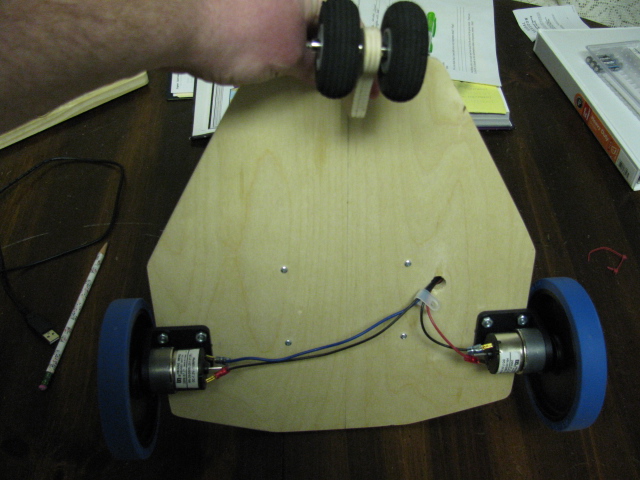
The chassis: 3/8 multi-ply plywood
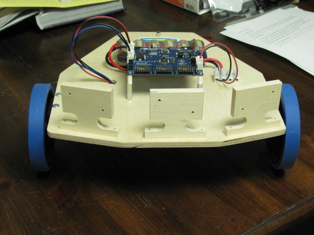
Controller: Propeller Robot Controller Board - #28230
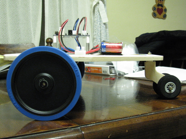
Battery: 6-cell, 4600 with Deans connector - held to chassis by Velcro
Motor/Wheels: Parallax 7.2v motor, Bracket and Wheel Kit - #570-0070
Connectors for Board power & Motor power: - Molex #0351560200 for plastic connectors (Mouser #538-35156-0200) and Mouser number for pins is 538-50217-8100 (Ordered both from Mouser and got initial info in Propeller Board manual available on Parallax.com)
Spade Connectors on motor: Dorman Products Inc. .110" (Found them at the local auto parts store in the electrical section and they are used for hooking up speakers and they are Gold Plated. Now doesn't that make you want to run out and by a case of them?)
Ping))) sensors: Stingray Ping Kit - #28985
Cool Detailing: Parallax Hat Decal - #125-00005 (Why don't they make a Propeller Decal for the car? Sure would make it easier to locate fellow Propeller Fans.)
I made my own ping))) sensor holders because Parallax was out of stock and well, I could make similar items in wood. After my Stingray Ping))) Kit gets here I will mount them and build guards that will be glued to the mounting boards on either side of the ping))) sensors and protrude out further than the sensor to protect them from an object strike or tip over.
First run was very enlightening! Using the motor test run code (in Board manual) to run both motors at the same time I downloaded the code to the board thinking in BOE-BOT speed that a 2 second motor run wouldn't take the robot too far. Man was I wrong!!! I set the robot down it raced across the floor near the speed of light right for my computer desk and Linux server box. I knew a crash was imminent and began chasing it. After hitting the desk and server, moving it about six inches, it began running the second half of the code, running the motors in reverse for 2 seconds. We met each other half way and when it slammed into my foot it felt like it broke my big toe! First run observation: Man this thing is fast and wear your steel toed work boots for the next test!
Sure hopes this inspires, like all the other cool plywood platforms did me, someone to get out in the shop and build. Nothing beats cabin fever like making a new robot with all the great products Parallax provides.
Tony
P.S. Erco, I think it needs some love handles.
Post Edited (Tony B.) : 4/29/2010 1:16:05 PM GMT
Update 2: 2-1-2010 - Chassis (posted below)
Update 3: 2-2-2010 - Pings and Mounts (posted below)
Update 4: 2-4-2010 - Updated chassis plans v1.1 (taller tailwheel to help robot run level and notch for ping wire to run through mount), posted tailwheel assembly plans and pictures
Update 5: 2-10-2010 - Added a direction diagram in hopes to make sure we are all on the same page.
Update 6: 2-22-2010 - Banshee goes to school at my son's 4th grade class and show picture of updated ping mounts with wire slot.
Update 7: 2-26-2011 - Added new mounting style for pings. Went from three to two on Parallax's Ping Mounting Bracket #570-28015
Update 8: 7-5-2013 - Added real brakes Post #61
Now I know this looks like the Stingray(a great design) and no I'm not trying to sell it. I wanted to show what I am doing with wood and the awesome Parallax product line. I know what you’re asking, "Why didn't he just buy a Stingray?" and that's a great questions. One, I already had the wheel set to build a two wheeled robot. Second, I'm a wood worker. Three, I had the battery, wheels and other supplies from my other hobbies (Control line airplanes & RC cars). Four, I wanted this robot to be an outdoor robot to test sensors and programming for competing in a robomagellan even and I was worried about the ground clearance of the Stingray. Five, by building the chassis and accessories myself I could show the Boss (my Wife) that I was saving money even when ordering the Propeller Robot Controller Board and Stingray ping))) Kit. As you can see she said yes.
The chassis: 3/8 multi-ply plywood
Controller: Propeller Robot Controller Board - #28230
Battery: 6-cell, 4600 with Deans connector - held to chassis by Velcro
Motor/Wheels: Parallax 7.2v motor, Bracket and Wheel Kit - #570-0070
Connectors for Board power & Motor power: - Molex #0351560200 for plastic connectors (Mouser #538-35156-0200) and Mouser number for pins is 538-50217-8100 (Ordered both from Mouser and got initial info in Propeller Board manual available on Parallax.com)
Spade Connectors on motor: Dorman Products Inc. .110" (Found them at the local auto parts store in the electrical section and they are used for hooking up speakers and they are Gold Plated. Now doesn't that make you want to run out and by a case of them?)
Ping))) sensors: Stingray Ping Kit - #28985
Cool Detailing: Parallax Hat Decal - #125-00005 (Why don't they make a Propeller Decal for the car? Sure would make it easier to locate fellow Propeller Fans.)
I made my own ping))) sensor holders because Parallax was out of stock and well, I could make similar items in wood. After my Stingray Ping))) Kit gets here I will mount them and build guards that will be glued to the mounting boards on either side of the ping))) sensors and protrude out further than the sensor to protect them from an object strike or tip over.
First run was very enlightening! Using the motor test run code (in Board manual) to run both motors at the same time I downloaded the code to the board thinking in BOE-BOT speed that a 2 second motor run wouldn't take the robot too far. Man was I wrong!!! I set the robot down it raced across the floor near the speed of light right for my computer desk and Linux server box. I knew a crash was imminent and began chasing it. After hitting the desk and server, moving it about six inches, it began running the second half of the code, running the motors in reverse for 2 seconds. We met each other half way and when it slammed into my foot it felt like it broke my big toe! First run observation: Man this thing is fast and wear your steel toed work boots for the next test!
Sure hopes this inspires, like all the other cool plywood platforms did me, someone to get out in the shop and build. Nothing beats cabin fever like making a new robot with all the great products Parallax provides.
Tony
P.S. Erco, I think it needs some love handles.
Post Edited (Tony B.) : 4/29/2010 1:16:05 PM GMT
640 x 480 - 152K
640 x 480 - 170K
640 x 480 - 192K

640 x 480 - 173K
Comments
Keep those updates coming, Tony!
▔▔▔▔▔▔▔▔▔▔▔▔▔▔▔▔▔▔▔▔▔▔▔▔
·"If you build it, they will come."
Edit - Tony, I had a chance check out your pics and specifications a bit more. I think it came out really well. I like your tailwheel and bracket. It looks very light too and ought to do well outside with the higher ground clearance. I think the homemade Ping))) brackets match the rest of the chassis nicely.
Great job! The motors are fast aren't they!
▔▔▔▔▔▔▔▔▔▔▔▔▔▔▔▔▔▔▔▔▔▔▔▔
Whit+
"We keep moving forward, opening new doors, and doing new things, because we're curious and curiosity keeps leading us down new paths." - Walt Disney
Post Edited (Whit) : 1/29/2010 4:55:45 PM GMT
The improvement s I have planned for the robot are:
1. Test stand to run robot on and not worry about it taking off
2. Carrying handles
3. Finer motor control using PWM because on/off is a little bit too rough on the motors and robot.
4. Ping))) sensors when they get here
5. LCD panel Havent decided on which one yet.
6. Homemade encoder system maybe using Parallax QTI sensors or the sensors Erco showed in the following forum post - http://forums.parallax.com/forums/default.aspx?f=10&m=420003
7. Parallax Accelerometer - # 28017
8. Parallax Compass module - # 29123
9. Parallax GPS module - # 28146 later # 28503 or maybe new modules just released
10. Data logging using either Parallax Memory Stick Datalogger - # 27937 or and most likely Parallax micro-SD Card Adapter - # 32312
11. Safety bumper switches/wires for missed objects
12. Cool blinking LEDs and sound
Hope to get test stand designed tonight and post the pictures and plans for it this weekend
Tony
Post Edited (Tony B.) : 4/8/2010 1:10:09 PM GMT
In picture 4 you can see that you can flip it over and have a small work table. My robotics tool box is on top to show it does work as a table and to hold the top to the base while the glue dries.
I’ll post the plans, but would like to know if forum members would like them in PDF or DXF format or both. With the DXF format you could load it into your CAD software and make full size printouts on 8 ½ x 14 paper of the parts you need to cut (supports and sides). I haven’t been able to make PDFs retain actual size no matter what I’ve tried. They always reduce the parts just a little to throw off all accuracy. Anyone solve this problem?
I have no way to test it, but with little to no modification I suspect this would work for the Stingray.
EDIT - Plans posted below.
Tony
Post Edited (Tony B.) : 4/8/2010 1:08:42 PM GMT
Ken Gracey
Here are the plans and instructions for building the Testing/Work Stand.
If Parallax has no objections
Ping))) kit arrived today
To use the DXF file make sure you right-click on the link and click "save target as"
Tony
Post Edited (T Bill) : 1/30/2010 9:42:27 PM GMT
No objections? No way - only support! Please share! That's why we offer the components - in hopes that people will do exactly what you've done. Glad to have another DIY chassis example that people can enjoy.
Ken Gracey
Parallax Inc.
Starting tomorrow I will be teaching electricity to the two 4th Grade classes at my son's elementary school. I will be teaching 8, 1/2 hour sessions to each class. Of course I will be getting they're attention by showing one of the greatest uses for electricity, building robots. I will be showing the BOE-Bot, Sumo Bot, this two wheeled robot and one other home made robot. I will also show them Parallax's website other robot videos.
Thanks,
Tony
Love the test stand. I am using a little box under my Stingray. Yours looks much more stable. Keep posting!
▔▔▔▔▔▔▔▔▔▔▔▔▔▔▔▔▔▔▔▔▔▔▔▔
Whit+
"We keep moving forward, opening new doors, and doing new things, because we're curious and curiosity keeps leading us down new paths." - Walt Disney
Here is another post - the plans for the chassis, tail wheel, and ping))) bracket. I will add pictures later tonight of tail wheel assembly and the Pings mounted as well as in a day or two the instructions and parts list.
To use the DXF file make sure you right-click on the link and click "save target as"
Tony
UPDATED PLANS 2-3-2010
Post Edited (T Bill) : 2/5/2010 1:53:43 AM GMT
I modified the mounts from the tall ones shown in the original photos in the first post.· The Chassis plans have the new design.· I think they look a lot better.·
One concern I had was the angle of the chassis to level.· The chassis is high in the front and made ·the ping sensor point up instead of level with the·ground.· It did throw the running off.· I leveled the chassis with a level ·by adding spacers to the tail wheel and the robot ran much better.
I had some issues with the “Pings on a Stingray” code.· The first issue was with the documentation that says to connect “the leftmost Ping to I/O three”· the right and center were to be connect to 0 and 1 respectively.· I thought it odd to hook it to three and not two.· I did it the way it said and nothing worked.· I moved it to 2 and everything worked great.· The second issue is covered in this post·http://forums.parallax.com/showthread.php?p=863896 switched the motor wires on the left motor and now it really roams great!!·
I need to work on tweaking the ping code for the outside pings I think because it would catch and hang on a corner.··Also, ·the minimum power sent to the motors is a little low.· Had some cases where the robot gets stuck and you could really hear the motors wine.
Inspired by Erco and his many good videos I am going to make a video and get it posted on YouTube.· That will be a first for me.
Edit: http://www.youtube.com/watch?v=Vjg_RIhvQyQ
Hope to have tail wheel pictures and plans real soon. ·(going to modify the tail wheel assembly to get the chassis closer to level).
I think I am going to call my robot "The Banshee"· because it is a screamer just like the Yamaha Banshee I use to ride and race.
The photos were taken by my son Matthew.
Tony
Post Edited (Tony B.) : 4/8/2010 1:12:04 PM GMT
Edit - By the way, I am still trying to figure·which part·the code makes the motor wiring on the Left motor need to be reversed (I know·reversing the wiring temporarily·solves the problem). I've been playing with it and I am not sure if the problem is in the Main program or the pwm object. I haven't been able to figure it out yet - I don't really want to change the wiring on the Stingray (since it tests properly, is wired per the instructions·and because standardization will matter as more code is written or we share with one another). Any ideas? Chris Savage hinted at this over on his site saying a earlier version of the Stingray was wired differently.
▔▔▔▔▔▔▔▔▔▔▔▔▔▔▔▔▔▔▔▔▔▔▔▔
Whit+
"We keep moving forward, opening new doors, and doing new things, because we're curious and curiosity keeps leading us down new paths." - Walt Disney
Post Edited (Whit) : 2/4/2010 2:01:40 AM GMT
Very nice craftsmanship on your bot. Clearly, you have·some·nice tools·and great woodworking skills; your ping holders look very professional, like wooden versions of the P'lax aluminum versions. I'll bet you could sell some of those to Forumites if you decide to go into mass production!·
▔▔▔▔▔▔▔▔▔▔▔▔▔▔▔▔▔▔▔▔▔▔▔▔
·"If you build it, they will come."
Post Edited (erco) : 2/4/2010 3:25:41 AM GMT
Did you ever think of making a wiring notch in the bottom to pass the wire through? Might work pretty well. I was thinking a half circle wide enough for the connector to slide through. It could hold the wire fixed as well.
Please see my edit above (in my previous post).
▔▔▔▔▔▔▔▔▔▔▔▔▔▔▔▔▔▔▔▔▔▔▔▔
Whit+
"We keep moving forward, opening new doors, and doing new things, because we're curious and curiosity keeps leading us down new paths." - Walt Disney
Post Edited (Whit) : 2/4/2010 1:57:49 AM GMT
That's a nice, sweet running machine, Banshee is befitting. Great video too!
Could you please post a copy of the code "Pings on Stingray" that you used? I would like to look at the why of left, right and center on your ping issue.
I’m glad to share this project!· Building and sharing our robots in community is a great way to go.· It helps keep me focused and motivated.·
I thought the video turned out OK as well.· I was really surprised just how easy the process was, but I learned the upload speed is nowhere near the download speeds.· I suspected this though.· I hope to post a new video later today shot in a larger area.
Whit, I haven’t studied the code yet on the wiring issue to the motors.· That was one of the goals for today.· You are right on when you say we have to keep a standard wiring plan for the Stingray.· What a mess if we don’t.· I’ll let you know what I come up with to help the discussion I have attached a diagram of my wiring as it is now.· Looking at the Stingray wiring, my black wires match its colored wires.· So, my left motor is wired opposite of the Stingray.· The right is the same. (Please make sure I have the pins right with the Propeller Robot Control Board).· Also, thanks for the slot suggestion on the mounts. I don’t like the wires flopping around like that.· It makes them too easy to get caught on something.· ·I will see what I can do.
Erco, thanks for the kind comments about my woodworking.· I will admit though there are some bloopers (clever camera angles to hide them).· It is so hard to slow down and do everything just right when you’re working in the shop bringing your latest creation to life.· I’ve tried to keep this robot simple and provide good plans and patterns so it can be built with just hand tools.· I’ll admit it though; it is really easy when you own a good collection of stationary power tools.· As you noted the mounts are patterned after Parallax’s mounts.· Parallax’s ·look good and provide protection that mine don’t.· I have a plan to address this issue, but not sure how it will look.· There’s nothing like polished aluminum to make you robot shine.· Going in to production?· It wasn’t my original intent (see first post), but with Parallax’s blessing I would think about it.· It would be a great joy of mine to see many new people getting involved in this great hobby.·
Rpdb, thanks for your comments.· I have posted the code below.· The issue with the pings was in the lead comment section of the code and not with the code its self.· In the code (Pings on a Stingray - Pri pings) expects to have the pings connected on pins 0,1,2, but the documentation block at the top of the "Pings on a Stingray" code, says hook them up to pins 0,1,3.· I initially hooked them as stated and they didn’t work.· I hooked· them up 0,1,2, and all worked well.
Tony
Updated Chassis plans "chassis v1.1" with updated tailwheel design and ping mount (slot for wires)
Post Edited (T Bill) : 2/5/2010 2:08:21 AM GMT
I believe you have the pins and your current wiring (left motor reversed) correctly shown. I figured that was you son in the video! I like the Ping))) bracket notch too!
What are you using to make your drawings?
▔▔▔▔▔▔▔▔▔▔▔▔▔▔▔▔▔▔▔▔▔▔▔▔
Whit+
"We keep moving forward, opening new doors, and doing new things, because we're curious and curiosity keeps leading us down new paths." - Walt Disney
Post Edited (Whit) : 2/5/2010 2:23:28 AM GMT
Just looked at the code, thanks for posting it. The pings are set to return values to an array of 3 globally accesable longs distance[noparse][[/noparse]0, 1 and 2] (left, center and right). It is an easy mistake for any of us to make on a zero based array to forget or confuse the third array member as 3 instead of 2 (zero is a number). You will see that Chip Gracey had the foresight to include commands such as lookup·vs. lookupZ where one works on a zero based array and the other starts at 1.
Hope that helps,
rpdb
· repeat
··· 'Read sensors
··· Left := Distance[noparse][[/noparse]1] * RISK_FACTOR <# Distance[noparse][[/noparse]2] * RISK_FACTOR···· 'left compared to center
··· Right := Distance[noparse][[/noparse]1] * RISK_FACTOR <# Distance[noparse][[/noparse]0] * RISK_FACTOR··· 'right compared to center
·········
24 - Reverse
25 - Forward
26 - Forward
27 - Reverse
In order for the SetMotor routine to work·for both motors,·the pin pairs must produce the same directions. It expects to be sent the lower pin of the pair and that pin to produce forward motion when PWM'd.
This arrangement follows the same logic that I used when hooking up the motor encoders. Instead of using the four pins attached as A,B,A,B, I attached them as A,B,B,A in order that forward wheel movement would produce positive numbers from·both wheels. Doing it otherwise, for both the wheel motors and the encoders, would require much more complex code to compensate for the mirroring of the left and right sides.
Duffer
▔▔▔▔▔▔▔▔▔▔▔▔▔▔▔▔▔▔▔▔▔▔▔▔
Any technology, sufficiently developed, is indistinguishable from magic.· A.C. Clark(RIP)
Thanks so much! Even better - It makes sense.
▔▔▔▔▔▔▔▔▔▔▔▔▔▔▔▔▔▔▔▔▔▔▔▔
Whit+
"We keep moving forward, opening new doors, and doing new things, because we're curious and curiosity keeps leading us down new paths." - Walt Disney
Post Edited (Whit) : 2/5/2010 7:56:12 PM GMT
Whit, I am using a CAD program called "TurboCAD Deluxe 16 2D/3D" it is sold by IMSIDesign. Their website is turbocad.com As you can see, I use the 2D part all the time and have worked with the 3D just a little. I have used this software for years. I want to learn and work more with 3D part as I develop more robots and accessories. I have a “Top Secret”
Tony
@Duffer, I PM'd Chris Savage about this to find out the scoop on why is the way it is.
▔▔▔▔▔▔▔▔▔▔▔▔▔▔▔▔▔▔▔▔▔▔▔▔
Whit+
"We keep moving forward, opening new doors, and doing new things, because we're curious and curiosity keeps leading us down new paths." - Walt Disney
My instructions for the Stingray say to hook up the colored (blue & green) wires to the positive terminals, and the white wires to the other terminal. This means that power applied in the "positive" direction across the terminals will result in the motors turning opposite directions (because they are rotated 180 degrees from eachother). That is why the two pins driving one motor are the opposite directions of the two pins driving the other motor. You could wire the motors differently to get things to match up on the pins if you wanted, but then your code will be different than other peoples code.
The code I downloaded for testing the pings (from the Stingray page in the store) has the motor controlling code setup to work with that arrangement (where the motors are wired as described and the pin pairs have opposite values for forward and reverse). I've verified this like 3-4 times now.
▔▔▔▔▔▔▔▔▔▔▔▔▔▔▔▔▔▔▔▔▔▔▔▔
Check out the Propeller Wiki·and contribute if you can.
Thanks for hanging in there with me on this question. Roy, my motor wiring is just as you decribed (which is per the intructions), but the code (Pings on a Stingray and Ping Demo) I have for testing the Pings - with no obstacle in front of the Pings -·makes the the right motor spin forward and the left motor spin in reverse.
Is this what you are verifying or are you saying that yours works correct when wired according to the instructions?
▔▔▔▔▔▔▔▔▔▔▔▔▔▔▔▔▔▔▔▔▔▔▔▔
Whit+
"We keep moving forward, opening new doors, and doing new things, because we're curious and curiosity keeps leading us down new paths." - Walt Disney
Post Edited (Whit) : 2/6/2010 2:41:18 PM GMT
▔▔▔▔▔▔▔▔▔▔▔▔▔▔▔▔▔▔▔▔▔▔▔▔
Whit+
"We keep moving forward, opening new doors, and doing new things, because we're curious and curiosity keeps leading us down new paths." - Walt Disney
I tried switching the wires on left motor to match Stingray and thought if I altered the code to set left_motor from 24 to 25 it would fix it.·
CON
· LEFT_MOTOR··· = 24··········· ' Lower I/O pin for the left motor
· RIGHT_MOTOR·· = 26··········· ' Lower I/O pin for the right motor
On my test run the·robot acted as it did on the first test run, spinning in circles.· Put everything back and it runs great.· Wish I could see what I'm missing.· I am baffled by Bocephus' results.· Is there two versions of the code out there? ·Is there an older one and a new one?
Will keep working on it because I would like to move on to new additions to the bot.
Tony
Post Edited (T Bill) : 2/6/2010 11:14:44 PM GMT
Just downloaded the software archive on the Stingray's product page and discovered it is quite different than the one I downloaded some time ago.
Old one is titled "PingsOnStingray - Archive"
The new one on Stingray Product page is titled "Stingray Demo"
I have attached both for you and others to compare.· It looks quite interesting.·
Post Edited (T Bill) : 2/6/2010 11:19:18 PM GMT
The one I have been using is the StingrayDemo.zip one. I never saw the older one.
▔▔▔▔▔▔▔▔▔▔▔▔▔▔▔▔▔▔▔▔▔▔▔▔
Check out the Propeller Wiki·and contribute if you can.