

Parallax Inc. Industrial I/O Board Preview
 Chris Savage
Parallax EngineeringPosts: 14,406
Chris Savage
Parallax EngineeringPosts: 14,406
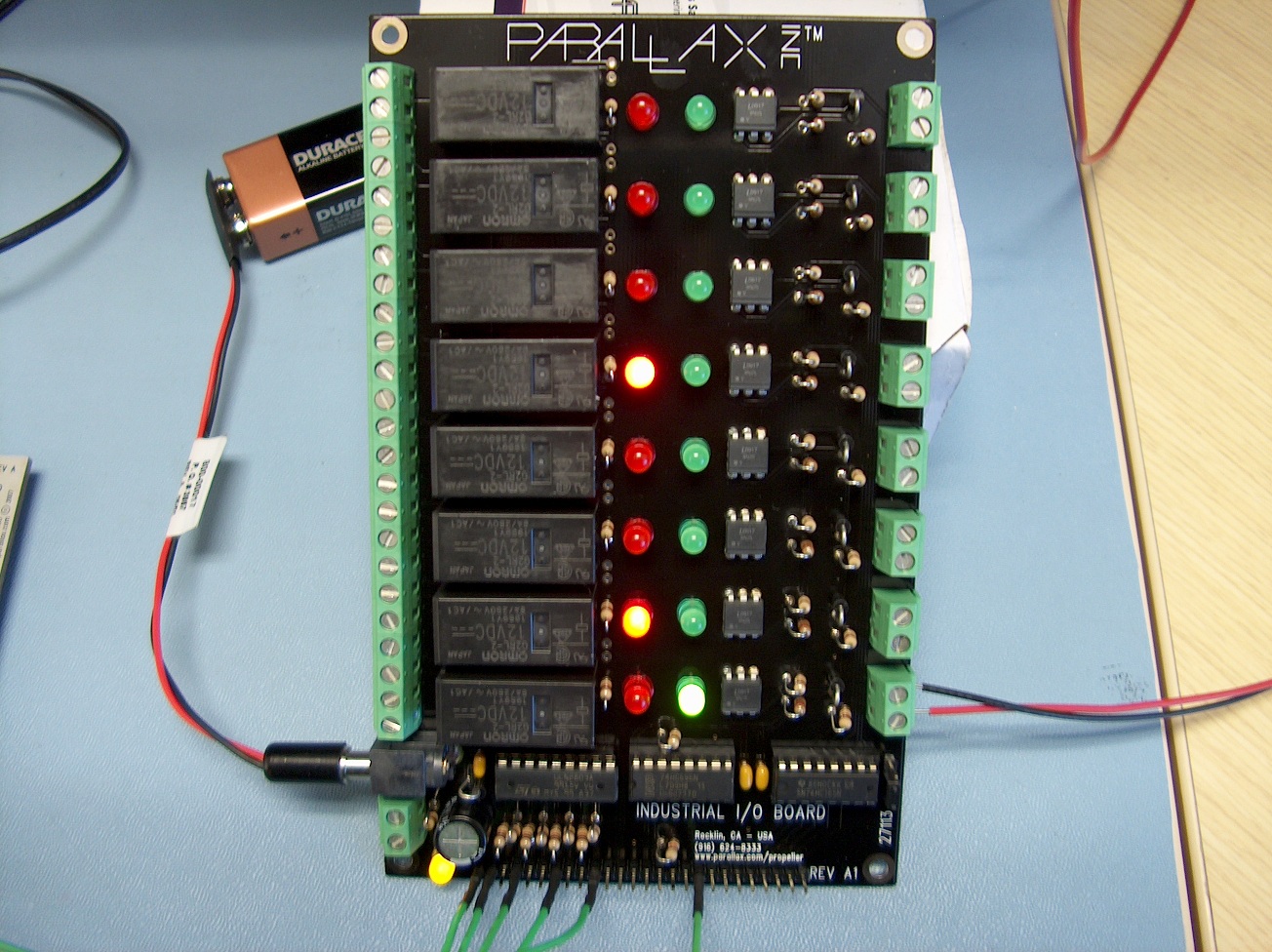
Thought some of you might like to see what it is that keeps me busy at Parallax...well, here's one such project.· Coming soon, the Parallax Industrial I/O Board.· A real quick run-down:
A picture is attached below and a link to a video of it is available as well.· Enjoy!
http://www.youtube.com/watch?v=0gpCMFdU2fo
▔▔▔▔▔▔▔▔▔▔▔▔▔▔▔▔▔▔▔▔▔▔▔▔
Chris Savage
Parallax Engineering
50 72 6F 6A 65 63 74 20 53 69 74 65
- (8) Optically Isolated Inputs - 5-30VDC (Can be configured for different voltage ranges)
- (8) Omrom 10A Relay Outputs (each relay can be replaced with an optional Sharp SSR)
- Parallel interface to both inputs and outputs
- SPI interface to inputs and outputs
- Mounting Holes
- DC Barrel Connector and Terminal Block for relay P/S (12V)
- Logic is 3.3V and 5V compatible
A picture is attached below and a link to a video of it is available as well.· Enjoy!
http://www.youtube.com/watch?v=0gpCMFdU2fo
▔▔▔▔▔▔▔▔▔▔▔▔▔▔▔▔▔▔▔▔▔▔▔▔
Chris Savage
Parallax Engineering
50 72 6F 6A 65 63 74 20 53 69 74 65
1304 x 976 - 550K
Comments
How about {approximate} $
▔▔▔▔▔▔▔▔▔▔▔▔▔▔▔▔▔▔▔▔▔▔▔▔
=================
The future is in our hands.
Which way to the future?
=================
▔▔▔▔▔▔▔▔▔▔▔▔▔▔▔▔▔▔▔▔▔▔▔▔
- Tony
http://zuzebox.wordpress.com/
▔▔▔▔▔▔▔▔▔▔▔▔▔▔▔▔▔▔▔▔▔▔▔▔
Chris Savage
Parallax Engineering
50 72 6F 6A 65 63 74 20 53 69 74 65
Post Edited (Chris Savage (Parallax)) : 11/19/2009 6:18:12 PM GMT
▔▔▔▔▔▔▔▔▔▔▔▔▔▔▔▔▔▔▔▔▔▔▔▔
Computers are microcontrolled.
Robots are microcontrolled.
I am microcontrolled.
But you·can·call me micro.
Want to·experiment with the SX or just put together a cool project?
SX Spinning light display·
Want cheap wholesale electronic parts?
Transistor parts wholesale
▔▔▔▔▔▔▔▔▔▔▔▔▔▔▔▔▔▔▔▔▔▔▔▔
Chris Savage
Parallax Engineering
50 72 6F 6A 65 63 74 20 53 69 74 65
·
Typically, commercial I/O racks designated for industrial use (such as those from Opto22, Grayhill, etc.) carry the Underwriter's logo, mainly (I'm guessing) due to the voltages and currents they have to cope with and as an indication that adequate protective devices exist to deal with short circuits, overvoltages, and the like. Was conformance to UL specs an objective in the design of this product, and does Parallax have any plans to pursue the Underwriter's seal?
Also, are there any plans to carry a DIN-rail mounting kit for this product?
Thanks,
-Phil
UL is something we're looking into. As for the DIN rail mounting, I'm not sure what are current plans are on that. Thanks for your interest. I will find out more over the next couple of weeks. Take care.
▔▔▔▔▔▔▔▔▔▔▔▔▔▔▔▔▔▔▔▔▔▔▔▔
Chris Savage
Parallax Engineering
50 72 6F 6A 65 63 74 20 53 69 74 65
·
Looks like a really useful building block. Couple of points..
1) For industrial it really needs to be able to operate from 24v dc. Could this be accomplished just by replacing the relays with a different model (as you describe for the sharp ssr's)
2) Why not silkscreen label the leds with IN0..IN7 and OUT0..OUT7. One less thing to have to think about for the end user.
3) I'm guessing the board is about 4" wide. Phoenix and Dinkle and others have extendible, din rail holders. They need a little bit of dead area at the side of the pcb but are very popular and designed for standard board sizes (75mm, 100mm etc)
cheers
tubular
The board in the picture is a prototype so silkscreen was not completed at that time. Future boards will have a complete silkscreen. Currently all feedback is being accumulated for consideration. Thank you for the link. I will check into that immediately. Take care.
▔▔▔▔▔▔▔▔▔▔▔▔▔▔▔▔▔▔▔▔▔▔▔▔
Chris Savage
Parallax Engineering
50 72 6F 6A 65 63 74 20 53 69 74 65
·
Also, if you've ever had to replace a rack or remove one for testing, features you come to appreciate very quickly are screw terminal blocks that you can pull off en masse from their headers, rather than having to loosen each screw and have a bunch of dangling wires that have to be reattached. It also saves wear and tear on the wire ends. The headers are available with standard pin spacings and will typcially just drop into a PCB designed for screw-terminal blocks without modification.
Chris, what are the dimensions of the board, and where are the hole centers? I'm thinking it may be pretty easy to make an adapter for the Phoenix DIN rail mounts (which I've used — they're pretty nice). DIN rail mounting prevents having separate screws and standoffs in the cabinet, resulting in less tooling for the back panel and less chance of a dropped screw getting lost. Moreover, standoffs always seem to unscrew from the bottom when you loosen the top screw, even with lockwashers, and that's a problem when the bottom screw is installed from the rear of the back panel.
I've installed and serviced control panels in some truly godawful places (and still have nightmares about it). Anything that minimizes time, loose wires, and dropped screws is a blessing when you're working on a control box whilst kneeling on a metal grate over a water flume, under the stern gaze of a plant manager whose two dozen production workers are standing idle.
Thanks,
-Phil
Post Edited (Phil Pilgrim (PhiPi)) : 11/21/2009 9:09:29 PM GMT
▔▔▔▔▔▔▔▔▔▔▔▔▔▔▔▔▔▔▔▔▔▔▔▔
Shawn Lowe
When all else fails.....procrastinate!
Your input is appreciated. To be honest I have worked in Industrial Control systems for years and one thing I noticed was that the boards designed specifically for these applications weren't really friendly with your average hobbyist with a BASIC Stamp or Propeller.· My original goal was to provide the same functionality and make it available to the average person not familiar with the boards used in Industrial applications. For example, a farmer who wants to use a BASIC Stamp to turn on his sprinklers in sequence or the artist who is trying to turn several neon lights on/off.· I had not considered the actual industrial applications themselves as that market is quite saturated, albeit at a higher cost.
The board is approximately 4" x 6" and if we were to add 24VDC capability for powering the relays it would need a regulator which would grow the board some. I will have to discuss these considerations with our engineering team. In the mean time do you think our design would best fit the average customer we have now or do you think the design implies true industrial control cabinet specifications?· It might help to know that (and I wasn't going to mention this yet originally) this will be a kit that the customer would build from the PCB up.
▔▔▔▔▔▔▔▔▔▔▔▔▔▔▔▔▔▔▔▔▔▔▔▔
Chris Savage
Parallax Engineering
50 72 6F 6A 65 63 74 20 53 69 74 65
Post Edited (Chris Savage (Parallax)) : 11/22/2009 5:47:53 PM GMT
Thougt I would put in my 2 cents worth.
Keepup the good work Chris and Parallax
[*]DC Barrel Connector and Terminal Block for relay P/S (12V) [*]··Or This would be nice then you use ether way·for Hobbies or· Industrial use
[*]DC Barrel Connector and Terminal Block for relay P/S (24V) [*]DIN-rail mounting kit· would be a nice
You have my·Vote which is YES and thump UP
····
Very Nice
▔▔▔▔▔▔▔▔▔▔▔▔▔▔▔▔▔▔▔▔▔▔▔▔
··Thanks for any·
·
·
·
·
Sam
Post Edited (sam_sam_sam) : 11/23/2009 2:45:16 AM GMT
I agree that the casual hobbyist will probably have more access to a 12V supply with a coaxial plug than to a 24V supply. But, without seeing a schematic, I'm missing the necessity for a regulator. It looks like you're using a ULN2803 to drive the coils, and it's rated to 50V. If a person wanted to use a 24V supply, couldn't they just substitute equivalent relays with 24V coils? (Rereading your specs, I see I missed the part about both a terminal block and a coaxial socket for the relay power. Also, I'm presuming the logic power comes via the header at the end, right?)
True enough about the saturation and, if you buy Siemens or Allen Bradley, the cost as well. However, it is possible to obtain a quite capable PLC these days for $79 from Automation Direct, a subsidiary of Koyo. I agree that this would be a difficult market to compete in against the likes of Koyo. My approach to the low end industrial market would be to leverage the products that are out there (by adding compatible sensors, for example), rather than competing head to head.
Armed with a better understanding now of your market objectives, I think you're on the right track with this design, and you should do well with it. One thing I would urge you to do, however, is to look at Parallax's other offerings and how they're pinned out. For example, both the Prop Demo Board and DB Expander have SIP pinouts that proceed: +5V x Vdd P0 ... P7 Vss, making them plug-compatible. Matching the pinout (for the serial I/O at least) with one or more of your other products gives you the opportunity to leverage those other products as well. (It may be as easy as using three or four 3-pin servo-style connectors, rather than five or six pins in a row.) In other words, the whole can be greater than the sum of its parts. Virtually all of Parallax's products, taken alone, are superbly designed. But my gut feeling is that Parallax occasionally misses opportunities to leverage their current products with the new ones that come along. In many cases, all it takes is a change in pinout.
Thanks for taking the time to review our comments, Chris!
-Phil
As your feedback is highly respected I thought it best to continue the dialogue here in the open and keep the customers in the loop.· All feedback is appreciated and certainly having a full understanding of what I was trying to present would make for more accurate feedback.· Let me see if I can fill in the blanks...
I totally understand this.· And here I thought I was so clever trying to come up with a name that fit the type/style of application without placing it into that category for use with that type of product.
The ULN is used to drive the relays...however to reduce part count the LEDs are driven in Parallel with the coil, so the resistor chosen for the LED is based on the anticipated coil voltage.· Since this is intended to be a kit the customer could just as easily replace the 1K resistor with a value suitable for driving the LED from 24V and use Omron 24V coil relays as well.· While I was thinking of the 12VDC supply, a regulator would have made both possible without changing much else, but resistors are very cheap so there is no reason not to do that.
The circuit for the SSR is also in Parallel with the LED and Omron relay, however the SSR and mechanical relays are mechanically interlocked so you cannot connect both at the same time.· When using an SSR you must add a resistor for the diode in the SSR.· The units we chose which are small enough to use in this design require external limitation unlike most Opto22 and Crydom units.· The current design already has the required pads for this resistor.
On many products this was an innate part of the design.· In this case though pretty much all Industrial I/O boards I have seen employ parallel I/O, so for that the pins are available.· I wanted to have the ability to serially shift data in/out from the board.· The current design allows for full duplex transmission of I/O data or you can connectthe clock and data lines together and save even more I/O.· This system also allows 3.3V and 5V interface and to answer your question, yes, that voltage is provided by the host microcontroller through that SIP header.· I would be interested in hearing your suggestions on arrangement of the header pins as currently I don't see a path of gain in terms of making the product more plug & play with other boards, but that may just be an oversight on my part.· If you like, you may call me at Parallax tomorrow around noon regarding the SIP header interface.· Take care.
▔▔▔▔▔▔▔▔▔▔▔▔▔▔▔▔▔▔▔▔▔▔▔▔
Chris Savage
Parallax Engineering
50 72 6F 6A 65 63 74 20 53 69 74 65
·
Thanks for the additional info!
That may well be the case. If you were to post (or email me) a schematic of the pinout (or just list the pins in order L->R), I'd be happy to take a look at it.
-Phil
From left to right...
▔▔▔▔▔▔▔▔▔▔▔▔▔▔▔▔▔▔▔▔▔▔▔▔
Chris Savage
Parallax Engineering
50 72 6F 6A 65 63 74 20 53 69 74 65
·
Thanks for posting the pin callouts. I've been thinking about this a lot since yesterday. Here is how I would do it:
This is my reasoning:
1. Dual row headers are easier to interface to ribbon cable. Single row headers typically require either flex cable (expensive) or crimped wires (tedious).
2. Dual row headers also provide more mechanical rigidity when used to mate a daughtercard. The daughtercard can also be smaller, since the pins aren't so spread out.
3. The headers are grouped: one set for parallel, one for serial. Each is self-contained with its own power and ground connections. 10- and 20-pin sizes are common for IDC connectors.
4. The lefthand set is AppMod compatible. Granted, there hasn't been much AppMod activity lately, but all the BOEs have it, and it would be a simple matter to extend a ribbon cable to the new I/O board. I've made the Vin jumper selectable, in case +12V is too much for the BOE to handle. If it can handle 12V, or if a lower-voltage supply were used for the relays (e.g. your 9V battery), the BOE could be powered from this panel, or vice-versa.
5. One row of the lefthand set is also compatible with the Propeller Demo board.
6. The serial I/O set of pins is self-contained, and it would be easy to design a small daughterboard for it with self-contained smarts and a +12V->Vdd regulator, or a transition board to another processor board.
Anyway, that's my take on it. It's not meant to hijack the design, but more to illustrate what I mean by "leveraging", which applies both to current products and to the opportunities it creates for future add-ons.
Thanks,
-Phil
Addendum: I also considered the Opto22 pinout for the parallel header, but they seem to have abandoned anything shorter than 50 pins, even for their 8-port panels. So that's not a real option.
_
Post Edited (Phil Pilgrim (PhiPi)) : 11/23/2009 8:39:16 PM GMT
Thanks for taking the time to add input to this project. First let me say that dual-row headers were originally requested for the design but I had rejected them. At the time stability and ease of connection were the proposed benefits, however I disagreed on the ease of connection via ribbon cable because I figured you’d require the same connection on the other side and I didn’t see that being a commonplace thing. At the time I figured pluggable wires would win as I tend to use them myself. You were the first person to mention the AppMod header and that does make sense. One thing to note is that the VSS pins are at the end of the AppMod header with the lower numbered I/O pins. So if I make that change I would probably reverse the VSS and VIN/VDD pins on the ends.
As for the serial header…would that not easily interface to the MOBO? It’s clever though and does not limit one from still using pluggable wires in the absence of the appropriate interface for ribbon cable. I also like the concept that the VIN could be used to power the host controller. This reduces the need for additional power supplies. And don’t worry about hijacking anything…if I was opposed to making changes to designs based on customer feedback I should not be working at Parallax. Ina way I have Ken Gracey to thank for your suggestions being taken into consideration anyway.
▔▔▔▔▔▔▔▔▔▔▔▔▔▔▔▔▔▔▔▔▔▔▔▔
Chris Savage
Parallax Engineering
50 72 6F 6A 65 63 74 20 53 69 74 65
·
With an adapter, certainly. I actually started to draw a pinout for a MoBo-compatible Hirose connector for the I/O board, but it seemed rather self-indulgent, and I was a little trepeditious of the reception it might get.
Although the Propeller Backpack (which also uses the MoBo interface) doesn't have the line-sharing and coprocessor issues, there's no physically-convenient way to plug it directly into a MoBo header on the I/O board. With a transition board, it could be oriented sideways, giving better access to the A/V and PropPlug connectors.
Connectors have always been the bane of my existence, design-wise, and I probably spend more time figuring out which ones to use and their pinouts than I do on any actual circuitry. But I think it makes a difference to the customer when he recognizes that there's easy compatibility among various products, even if it's not taken advantage of in the end.
Anyway, thanks for considering my ideas (and thanks to Ken, too
-Phil
Addendum: Although any daughterboards that might be designed to interface to the two-row headers would probably stay put just fine, it might be nice to have additional mounting holes for them at the ends of the headers, centered on the header centerline. That way, standoffs could be incorporated to provide additional stability for horizontally-mounted boards.
Post Edited (Phil Pilgrim (PhiPi)) : 11/23/2009 11:45:37 PM GMT
▔▔▔▔▔▔▔▔▔▔▔▔▔▔▔▔▔▔▔▔▔▔▔▔
Chris Savage
Parallax Engineering
50 72 6F 6A 65 63 74 20 53 69 74 65
·
specific industrial boards that I would have loved to use but the cost put them out of reach. So I guess my comment/question would be if Parallax can keep it within the reach of the Basic Stamp, Prop users I would be be in line to purchase one.
Thanks
That is the main reason we're making it a kit. Customers of the skill level to implement a product like this should be fluent in soldering. Given that, it makes sense to provide a kit, especially in light of the fact that some parts of the kit can be changed such as resistors on the inputs and substituting Mechanical Relays for an SSR. All these things speak kit, which also means passing along the savings to the customer. I will have some ideas on cost in the next couple of weeks or so. We're a little early on this still. I am considering seriously a few changes based on customer feedback. That should also tell you how valuable our customers opinions are. If something makes sense and there are no cons to it, then it makes sense to do it. Thanks for your interest. Take care.
▔▔▔▔▔▔▔▔▔▔▔▔▔▔▔▔▔▔▔▔▔▔▔▔
Chris Savage
Parallax Engineering
50 72 6F 6A 65 63 74 20 53 69 74 65
·
After wanting to gouge my eyes out working with Microsoft I decided to get back into electronics and learn MCU's I spent so much money on PICS and ARMs and was not happy at all. I found Parallax by accident and can not tell you how much fun I have been having designing
stuff and building the Parallax kits my BoeBot has everything I am happy to tell you guys how unique Parallax is as far as support and concern for your customers you guys have hit on a great concept "take care of your customers and they will buy stuff from you" LOL
Seems like an easy thing right? Well you guys do it the best and I for one tell anyone that is into this type of thing how great you guys are at support and products. Even the way you have handled this new board. Don't ever change and I will be happy to keep spending money on your new products no matter how mad my wife gets at all the "Smile" her words not mine robots that wonder around the house "scratching the hard wood floors" lol
Oh and everyone have a happy and safe thanksgiving
Screw type treminals for the 'Real World' connections are a good idea.
A little off topic, but..
I have been using Stamps in an industrial environment for over 10 years.
We receintly rebuilt a machine that we upgraded in 1998 (or1999) with a Stamp II and solid state relays.
I cant get into my office computer, but I will post pictures tomorrow. It was still working when we removed it
It ran 3 shifts a day 5 days a week for over 10 years. Whn I removed the box, I discovered I was the first one to open it since we installed it. (The cover was still painted closed from when we installed it)
I have also made Stamp I & II PC boards that connect to the 50 pin headers on Opto-22 SSR Boards.
Automation Direct makes some very good and cheap PLC's. We use them on many of our automated Plasma Cutting machines.
A $99 'Brick' PLC can only handle one type of Input and Output. All DC, all AC, or Relay oputputs.
Lots of times we need to deal with AC and DC inputs & outputs on the same machine. When you buy a bigger rack with all the diffrent types of I/O modules you can get over $1-2k easily.
A Stamp connected to a universal type of board is easier to interface to smaller projects.
More rambling on tomorrow.
Thanks,
▔▔▔▔▔▔▔▔▔▔▔▔▔▔▔▔▔▔▔▔▔▔▔▔
Alan Bradford ·N1YMQ
Plasma Technologies
Canaan NH 03741
www.plasmatechnologies.com
▔▔▔▔▔▔▔▔▔▔▔▔▔▔▔▔▔▔▔▔▔▔▔▔
Post Edited (CounterRotatingProps) : 11/27/2009 10:08:46 PM GMT
▔▔▔▔▔▔▔▔▔▔▔▔▔▔▔▔▔▔▔▔▔▔▔▔
Chris Savage
Parallax Engineering
50 72 6F 6A 65 63 74 20 53 69 74 65
·