

Propellering the COBY DP151 - A PocketProp :)
 jazzed
Posts: 11,803
jazzed
Posts: 11,803
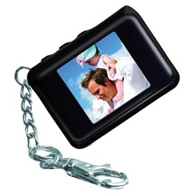
I was wandering through the local Fry's and found the COBY-DP151 Digital Photo Keychain for $11. Well, at that price I couldn't resist the "hack it up" urge. After being thouroughly accosted at the door by the receipt checker, I made it home with my new toy.
What is a DP151? It is a 1.44" diagonal photo-frame on a key-chain. It comes equipped with an LCD, a USB port and software in the flash, 3 user buttons, a rechargable ~4V 180mah lipo battery, a very nice little case, and a keychain.
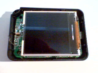
Taking the device apart was fairly easy by removing 2 screws and nudging apart the tiny clam-shell. I was immediately delighted by the look of the LCD packaging and the fact that a part-numb er was printed on the side. I slowly detached the LCD panel from the gluey foam and found a cute chip connected to the LCD pins.
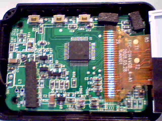
I Googled the various part-numbers on the LCD and found the most promising link at varitronix-hk.com. It turns out that the LCD is a CTSN technology and the specsheet is available by email. There I found the controller is an ST7687S and I was able to find a specsheet for that too.
With two important specs in hand, I decided to look up the chip which is an AppoTech AX206 which appears to be a really nice mask-rom 8051 controller with a USB2.0 interface and lots of GPIO. I could not find a detailed spec on that exact PN, but did find a spec for the AX203 in a zip package that amazingly contained another LCD spec that would be compatible with the varitronix LCD.
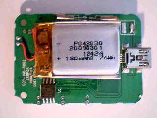
Looking around on the other side of the PCB and starting to really appreciate this package with the USB port and 4V rechargable battery, I noticed an 8 pin SOIC that is marked 25L080. Well that's a large serial flash device [noparse]:)[/noparse]
During my browsing for all the specs I came accross an article for hacking the COBY DP151-SX. The SX has a different CPU and flash and looks really good for PC-USB driven photo-frame hacking. This got me thinking that I should really leave the USB device in tact so I can download BMPs for Propeller game sprites [noparse]:)[/noparse] We'll see if I can hook the Propeller to it.
So, what is the plan? That's defined by the resources at hand. It looks like the LCD might be fully update-able at about 100 times/second by the Propeller. The write cycle time minimum is 200ns and the read cycle time (yeah read-modify-write!) is 400ns. So it looks entirely possible to have live real-time video ... we'll see.
The current plan is to detach the LCD 8 bit 8080 interface from the 8051, keep the 8051 in-circuit for power management and USB, and connect the Propeller to the LCD using 13 pins total (there is a SDIO mode, but the parallel interface looks good to me[noparse]:)[/noparse].
Looks like plenty of wiggle-room for adding Propeller hooks to the buttons. I think I'll intercept the center config button function and let Propeller send the power-up/down sequence and other AX206 software interface sequences. The other buttons can be used for game-play or whatever.
So 13 + 3 = 16 generic Propeller pins allocated so far (and 4 pins for Serial communications and EEPROM access), and we still have 12 pins left for fun. Gee, I've never had it so good [noparse]:)[/noparse]
Tomorrow I plan to disconnect the AX206 from the LCD and install a Propeller QFP, EEPROM, crystal, and Prop-Plug header. My backup plan (in case I destroy the QFP) is to use mctrivia's PropMod 1x1, but even that is too big.
So far, my $11 gamble has turned out pretty good. I'll post an update tomorrow.
More to come ....
▔▔▔▔▔▔▔▔▔▔▔▔▔▔▔▔▔▔▔▔▔▔▔▔
--Steve
Propalyzer: Propeller PC Logic Analyzer
http://forums.parallax.com/showthread.php?p=788230
Post Edited (jazzed) : 7/7/2009 10:26:36 PM GMT
What is a DP151? It is a 1.44" diagonal photo-frame on a key-chain. It comes equipped with an LCD, a USB port and software in the flash, 3 user buttons, a rechargable ~4V 180mah lipo battery, a very nice little case, and a keychain.
Taking the device apart was fairly easy by removing 2 screws and nudging apart the tiny clam-shell. I was immediately delighted by the look of the LCD packaging and the fact that a part-numb er was printed on the side. I slowly detached the LCD panel from the gluey foam and found a cute chip connected to the LCD pins.
I Googled the various part-numbers on the LCD and found the most promising link at varitronix-hk.com. It turns out that the LCD is a CTSN technology and the specsheet is available by email. There I found the controller is an ST7687S and I was able to find a specsheet for that too.
With two important specs in hand, I decided to look up the chip which is an AppoTech AX206 which appears to be a really nice mask-rom 8051 controller with a USB2.0 interface and lots of GPIO. I could not find a detailed spec on that exact PN, but did find a spec for the AX203 in a zip package that amazingly contained another LCD spec that would be compatible with the varitronix LCD.
Looking around on the other side of the PCB and starting to really appreciate this package with the USB port and 4V rechargable battery, I noticed an 8 pin SOIC that is marked 25L080. Well that's a large serial flash device [noparse]:)[/noparse]
During my browsing for all the specs I came accross an article for hacking the COBY DP151-SX. The SX has a different CPU and flash and looks really good for PC-USB driven photo-frame hacking. This got me thinking that I should really leave the USB device in tact so I can download BMPs for Propeller game sprites [noparse]:)[/noparse] We'll see if I can hook the Propeller to it.
So, what is the plan? That's defined by the resources at hand. It looks like the LCD might be fully update-able at about 100 times/second by the Propeller. The write cycle time minimum is 200ns and the read cycle time (yeah read-modify-write!) is 400ns. So it looks entirely possible to have live real-time video ... we'll see.
The current plan is to detach the LCD 8 bit 8080 interface from the 8051, keep the 8051 in-circuit for power management and USB, and connect the Propeller to the LCD using 13 pins total (there is a SDIO mode, but the parallel interface looks good to me[noparse]:)[/noparse].
Looks like plenty of wiggle-room for adding Propeller hooks to the buttons. I think I'll intercept the center config button function and let Propeller send the power-up/down sequence and other AX206 software interface sequences. The other buttons can be used for game-play or whatever.
So 13 + 3 = 16 generic Propeller pins allocated so far (and 4 pins for Serial communications and EEPROM access), and we still have 12 pins left for fun. Gee, I've never had it so good [noparse]:)[/noparse]
Tomorrow I plan to disconnect the AX206 from the LCD and install a Propeller QFP, EEPROM, crystal, and Prop-Plug header. My backup plan (in case I destroy the QFP) is to use mctrivia's PropMod 1x1, but even that is too big.
So far, my $11 gamble has turned out pretty good. I'll post an update tomorrow.
More to come ....
▔▔▔▔▔▔▔▔▔▔▔▔▔▔▔▔▔▔▔▔▔▔▔▔
--Steve
Propalyzer: Propeller PC Logic Analyzer
http://forums.parallax.com/showthread.php?p=788230
Post Edited (jazzed) : 7/7/2009 10:26:36 PM GMT
280 x 280 - 14K
320 x 240 - 52K
320 x 240 - 90K
320 x 240 - 14K
Comments
Failure to have power applied via USB or battery with Prop-Plug attached may cause damage to your Prop-Plug.
Starting the rework process now ....
Considering the complexity of the task, I expect to offer two PCB solutions to make this hardware hack work:
Warning, these rework steps are historical and incomplete. I do not recommend following them to the letter.
At some point, I will create a schematic that you can implement yourself.
Rework (so far):

Even with the LCD off, there is still power to the AX206 from the battery.
Be careful to not touch any other pins besides the ones mentioned here.

- Lift (or more practically cut off) pins AX206 1-6, 26-27, 30-31, 48 ... not sure about bit D0 yet.

- Remove and save 5.1K resistors R12 & R13 (marked in yellow) near the left and right switches.
  Will use these later so don't lose them.

- Remove C1 (above R13 and the right side switch) and excess solder to make room for Propeller.

- Solder the old R12 5.1K resistor from C17 to the left side switch.

[s]- Scratch the trace connecting to C1 pad to form a connection point for 3.3V.
  Make the scratch pretty big, and tin it ... you can use this for Propeller power later.
- Solder the old R13 5.1K resistor from the scratched 3.3V trace to R13 pad connecting to the
  right side switch. [/s]

The Menu (center) button is attached to AX206 37.  We will leave this connected.

Prepare the QFP (or QFN) Propeller:

The Propeller chip will be soldered upside down (dead-bug style). The main reasons for this are
1) we need to bend the QFP pins so they don't touch other components, 2) the QFN pins if used
are more accessible upside down, 3) makes it easier to solder +3.3V and ground, and 4) the LCD
data-bus counts left to right D0-D7 which makes point to point connections cleaner.

If using QFP, with the chip right-side up bend all leads toward the bottom of the chip.
If using QFN, there are no pins to bend :)

- On the QFP, solder wire-wrap wire in a cross shape with a loop at the head between pins
5, 6, 17, 27, and 39 on the bottom of the chip leaving about a 2" tail for connecting to the
board and the first pin (left to right) of a 4 pin male breakaway header. On the QFN, you can
solder the pins to the bottom plate, but you still need a tail for soldering to the board and the
breakaway header.

- Solder wire-wrap wire in another cross shape with a loop at the head between pins
8, 18, 30, and 40 on the bottom of the chip leaving about a 2" tail for connecting to the board.

- Soler wire-wrap wire from pin 7 RESn leaving room to solder a small smt pull-up chip resistor
between pin 7 and 8. Connect wire to 4 pin header pin 2. When the serial EEPROM is connected
later, a 10K chip resistor will need to be connected to RESn.

- Solder wire-wrap wire from pin 31 to pin 3 of the 4 pin header.

- Solder wire-wrap wire from pin 30 to pin 4 of the 4 pin header.

TEST PROPELLER:

BEFORE APPLYING POWER MAKE SURE: 3.3V to ground resistance is greater than 20K ohms.

- Connect Propeller 3.3V wire to a power source that does not exceed 4.0VDC.

- Connect Propeller ground to power source ground.

- Connect PropPlug to 4 pin header and check if chip is found with Propeller Tool IDE F7.

ADD PROPELLER TO PCB:

THE PROFILE OF PROPELLER MUST BE AS LOW AS POSSIBLE.

- Use hot glue to secure Propeller upside down with pin 1 close to center button.

- Add 1.2K 3.3V pull-up to LCD connector pins 12, 16, 26, 27.

- Connect LCD connector to Propeller as follows:

  LCD 12 CS - Ground
  LCD 16 RD - Prop 20  P17
  LCD 26 WR - Prop 21  P18
  LCD 27 A0 - Prop 22  P19

  LCD 18 D7 - Prop 4   P7
  LCD 19 D6 - Prop 3   P6
  LCD 20 D5 - Prop 2   P5
  LCD 21 D4 - Prop 1   P4
  LCD 22 D3 - Prop 44  P3
  LCD 23 D2 - Prop 43  P2
  LCD 24 D1 - Prop 42  P1
  LCD 25 D0 - Prop 41  P0

- Bit D0 is a problem. ... see below.

- Connect 5MHz crystal to Prop 28 & Prop 29

- Glue crystal in place with top facing the edge of board (see floorplan).

CONNECTING EEPROM: ... TBD ...
Note the Propeller floorplan below.
Legend: Cyan - Propeller, Grey - Crystal, Purple/Gold - PropPlug, Magenta - uSD?
With AX206 installed: After doing the cuts, the LCD back light still works (no display of course).
The center button still works.
- To turn on power press and hold the center button until the back light comes on.
- To turn off power press the center button twice slowly.
With AX206 cut off the board, the LCD driver needs to be enabled using the transistor in the red square.
Something else from the AX206 drives the D0 pin. Cutting the AX206 completely off the board is desirable.
If you do that, you need to enable the LCD back light by setting the back light transistor driver base to 0V
... see attached picture. The red square marks the transistor. The red pad on the transistor should be
attached to ground or a Propeller pin with a small 100Ohm resistor.
WARNING: BE CERTAIN THAT POWER IS APPLIED TO DEVICE FROM USB OR BATTERY IF USING PROP-PLUG.
Failure to have power applied via USB or battery with Prop-Plug attached may cause damage to your Prop-Plug.
▔▔▔▔▔▔▔▔▔▔▔▔▔▔▔▔▔▔▔▔▔▔▔▔
--Steve
Propalyzer: Propeller PC Logic Analyzer
http://forums.parallax.com/showthread.php?p=788230
Post Edited (jazzed) : 7/17/2009 5:09:24 PM GMT
Jazzed do you think this unit can be made to work stand alone with the prop what I mean is can the prop drive this LCD without any other support chips?
it would make a nice color display for a robot project
Sorry about the link problem ... the forum editor is corrupting it. Just go to http://www.cobyusa.com and click on Digital Home -> Digital Photo Frames.
I believe Prop can drive the LCD, but there are other requirements for back light + and - square wave voltages, etc... which the accessory circuits on the DP151 provide; these may not be trivial. I'll attach some pictures of the PCB in a while.
The DP151 is available from Amazon and other places at about $14 and beats the heck out of the equivalent SparkFun LCD board ($39) which may or may not have the switching regulator teen-annoyance whine fixed. The SparkFun LCD also sucks way too much current.
Here's a Fry's link: www.frys.com/product/5439059?site=sr:SEARCH:MAIN_RSLT_PG
▔▔▔▔▔▔▔▔▔▔▔▔▔▔▔▔▔▔▔▔▔▔▔▔
--Steve
Propalyzer: Propeller PC Logic Analyzer
http://forums.parallax.com/showthread.php?p=788230
Post Edited (jazzed) : 7/6/2009 5:25:44 PM GMT
But, since you know the display's driver IC model and the pinout, I think you have 1/2 the battle won already.
▔▔▔▔▔▔▔▔▔▔▔▔▔▔▔▔▔▔▔▔▔▔▔▔
My Prop Info&Apps: ·http://www.rayslogic.com/propeller/propeller.htm
I don't know but I have to try just about all the displays you guys post about and I know I drove poor Rayman crazy," I really did "and I apologies to him but thats what he gets for being the resident LCD expert,, lol no he is a real decent guy and did not hesitate to help me out
anyway Jazzed thanks I will check your progress ... I built a little robot that would be awesome if I had a small affordable color display to send debugging stuff to
@mikediv, I think this will work. If not, they make great little gifts ... my girls like them.
I've gotten the first big hurdle with a QFP Propeller powered by a 3.6V NiMh and identified with Propeller tool.
Gotta clean up those rework instructions and see if the rats-nest will fit in the photo-frame package.
More to come ....
▔▔▔▔▔▔▔▔▔▔▔▔▔▔▔▔▔▔▔▔▔▔▔▔
--Steve
Propalyzer: Propeller PC Logic Analyzer
http://forums.parallax.com/showthread.php?p=788230
Find it here:
http://www.rayslogic.com/Propeller/Products/PSM/Files.htm
As you may already know, the startup procedure is unique to every device...
▔▔▔▔▔▔▔▔▔▔▔▔▔▔▔▔▔▔▔▔▔▔▔▔
My Prop Info&Apps: ·http://www.rayslogic.com/propeller/propeller.htm
I bought a super cheap game with keyboard, buttons, and an LCD once. The LCD turned out to be segmented.
Guess I can put another LCD in it some day, but it will be a pain.
▔▔▔▔▔▔▔▔▔▔▔▔▔▔▔▔▔▔▔▔▔▔▔▔
--Steve
Propalyzer: Propeller PC Logic Analyzer
http://forums.parallax.com/showthread.php?p=788230
Works with RCFAST and crystal. Everything except EEPROM in the package now [noparse]:)[/noparse]
The LCD sits on top of the Propeller and the mess of wires and makes it impossible at this point to
screw the enclosure completely tight.·It's not too bad though; a gap of only 0.05 inch is in the edge.
Will update rework instructions soon. Soldering wire-wrap wire to Propeller QFP pins is pretty hard.
Having a little extra solder on the wire tip makes it easier. You need steady hands [noparse]:)[/noparse]
I always make sure I have a place to anchor my pinky fingers.
Now, time to write some driver code.
▔▔▔▔▔▔▔▔▔▔▔▔▔▔▔▔▔▔▔▔▔▔▔▔
--Steve
Propalyzer: Propeller PC Logic Analyzer
http://forums.parallax.com/showthread.php?p=788230
Post Edited (jazzed) : 7/7/2009 10:11:24 PM GMT
Great Job So Far.
Rick
▔▔▔▔▔▔▔▔▔▔▔▔▔▔▔▔▔▔▔▔▔▔▔▔
Prop Forum Search (Via Google)
You still have room for a microSD adapter in there. [noparse]:)[/noparse] [noparse]:)[/noparse]
{Nice work!}
OBC
▔▔▔▔▔▔▔▔▔▔▔▔▔▔▔▔▔▔▔▔▔▔▔▔
New to the Propeller?
Visit the: The Propeller Pages @ Warranty Void.
Still have to write that LCD driver .... Has anyone used "PocketProp" before?
I have room for EEPROM,·small piezio speaker,·and maybe a mike for that speech recognition code [noparse]:)[/noparse]
The power for charging and development is coming from the USB port ... very comfortable.
▔▔▔▔▔▔▔▔▔▔▔▔▔▔▔▔▔▔▔▔▔▔▔▔
--Steve
Propalyzer: Propeller PC Logic Analyzer
http://forums.parallax.com/showthread.php?p=788230
I screwed four standoffs onto the PSM and thought I was the man.
Looking really good.
Unfortunately I accidently destroyed something about the AX206 chip, so now USB won't work.
The battery charger still functions (I think) so it must be a separate circuit.
I suspect the AX206 can be completely removed since it is crippled ... but will not do that this time.
I had assumed that the data bus pins are contiguous bits coming out of the AX206. This doesn't
appear to be the case as what would be bit 0 comes from another pin group. Reworking this because
of a fight between Propeller and the AX206 is the reason the AX206 is crippled now :< oh well.
The large square-wave voltages for the LCD actually come from the LCD controller. Only capacitors
are needed for these voltages. There is a bias voltage going to the LCD that I haven't investigated yet.
▔▔▔▔▔▔▔▔▔▔▔▔▔▔▔▔▔▔▔▔▔▔▔▔
--Steve
Propalyzer: Propeller PC Logic Analyzer
http://forums.parallax.com/showthread.php?p=788230
Post Edited (jazzed) : 7/8/2009 8:36:23 PM GMT
I too have always been fasinated with the prop and displays.
▔▔▔▔▔▔▔▔▔▔▔▔▔▔▔▔▔▔▔▔▔▔▔▔
Toys are microcontroled.
Robots are microcontroled.
I am microcontroled.
If it's not Parallax then don't even bother. :-)
·
Mini-Din/PS2 connectors are for sale! 5 for $1! PM me if you wish to make an order.
Cheap·shipping unless specified!··········150 left!!··
I could see some really neat apps with those buttons, LCD and memory & of course the usb to change/load.
▔▔▔▔▔▔▔▔▔▔▔▔▔▔▔▔▔▔▔▔▔▔▔▔
Links to other interesting threads:
· Home of the MultiBladeProps: TriBladeProp, RamBlade, TwinBlade,·SixBlade, website
· Single Board Computer:·3 Propeller ICs·and a·TriBladeProp board (ZiCog Z80 Emulator)
· Prop Tools under Development or Completed (Index)
· Emulators: Micros eg Altair, and Terminals eg VT100 (Index) ZiCog (Z80), MoCog (6809)
· Search the Propeller forums (via Google)
My cruising website is: ·www.bluemagic.biz·· MultiBladeProp is: www.bluemagic.biz/cluso.htm
Added: I think it might be better to replace the original PCB entirely though. Not sure how one could safely remove the LCD.
▔▔▔▔▔▔▔▔▔▔▔▔▔▔▔▔▔▔▔▔▔▔▔▔
--Steve
Propalyzer: Propeller PC Logic Analyzer
http://forums.parallax.com/showthread.php?p=788230
Post Edited (jazzed) : 7/9/2009 5:44:46 AM GMT
No horrible chemicals, etc and recyclable.
Back to reality. Thinner pbcs can be bought at a premium.
What about removing the processor and gluing a prop upside down with kynar wire to make the connections? Kynar wire is the wire-wrap wire - nice and thin so it looks more professional and not so cumbersome, but harder to strip unless you have a tool.
▔▔▔▔▔▔▔▔▔▔▔▔▔▔▔▔▔▔▔▔▔▔▔▔
Links to other interesting threads:
· Home of the MultiBladeProps: TriBladeProp, RamBlade, TwinBlade,·SixBlade, website
· Single Board Computer:·3 Propeller ICs·and a·TriBladeProp board (ZiCog Z80 Emulator)
· Prop Tools under Development or Completed (Index)
· Emulators: Micros eg Altair, and Terminals eg VT100 (Index) ZiCog (Z80), MoCog (6809)
· Search the Propeller forums (via Google)
My cruising website is: ·www.bluemagic.biz·· MultiBladeProp is: www.bluemagic.biz/cluso.htm
and if I am lucky using the Dip package prop·I have a rather small to me anyway hobby box that radio shack sells I use them a lot
then can just hot glue them to my robot platfrom,, I cant wait until you get these to display text / graphics, imagine if we could do video that would be cool
·
I've done some risky experiments today. I chopped the AX206 chip off the board entirely (there is a second land-pattern there). Had to add a wire for the back-light LED driver; the driver appears to be a common-collector transistor driver. This frees all 3 buttons on the enclosure. Also, I tied chip-select to ground. The lithium-ion battery charger seems to be working fine without uC intervention.
I worked on ideas to make animation flicker-free, but had no luck. A tearing signal is available on the controller, but not brought out to the LCD connector [noparse]:)[/noparse] Too bad, because a lot can be done in 15ms ... the status is not available in a register either as far as I can tell.
Scrolling and partial display work now.
See Scrolling Demo www.youtube.com/watch?v=lj4hUJmNot0
Here's another Scrolling Demo www.youtube.com/watch?v=gijQM0BhErY
▔▔▔▔▔▔▔▔▔▔▔▔▔▔▔▔▔▔▔▔▔▔▔▔
--Steve
Propalyzer: Propeller PC Logic Analyzer
http://forums.parallax.com/showthread.php?p=788230
Post Edited (jazzed) : 7/10/2009 1:23:44 AM GMT
Can you place a socket instead of pins for the PropPlug ? You could use an adapter (tiny piece of vero) with 4 pins to 4 pins so that the pins don't have to protrude from your module.
And its more of a KeychainProp isn't it??
▔▔▔▔▔▔▔▔▔▔▔▔▔▔▔▔▔▔▔▔▔▔▔▔
Links to other interesting threads:
· Home of the MultiBladeProps: TriBladeProp, RamBlade, TwinBlade,·SixBlade, website
· Single Board Computer:·3 Propeller ICs·and a·TriBladeProp board (ZiCog Z80 Emulator)
· Prop Tools under Development or Completed (Index)
· Emulators: Micros eg Altair, and Terminals eg VT100 (Index) ZiCog (Z80), MoCog (6809)
· Search the Propeller forums (via Google)
My cruising website is: ·www.bluemagic.biz·· MultiBladeProp is: www.bluemagic.biz/cluso.htm
Would like to figure out how to make use of that USB connector other than for just a battery charger.
PocketProp has good alliteration [noparse]:)[/noparse] But I do like KeychainProp too.
This thing has been running on battery for more than 4.5 hours now with the LCD fully lit [noparse]:)[/noparse] Guess I need to measure current consumption.
I've started working on drawing lines now. After that I'll do some miscellaneous small things like putpixel and clear screen. Then I'll import my 5x9 mono spaced character set. Finally on software, I'll do some sprite/image routines. I'm afraid this display will never run a smooth graphics demo.
I still have to connect the buttons, the big flash, Propeller boot EEPROM, and other devices. Somewhere in the middle of all that, I'll look at publishing some good dimensions so that anyone interested in providing a PCB for this will have enough information to begin a schematic/pcb layout (me included [noparse]:)[/noparse].
▔▔▔▔▔▔▔▔▔▔▔▔▔▔▔▔▔▔▔▔▔▔▔▔
--Steve
Propalyzer: Propeller PC Logic Analyzer
http://forums.parallax.com/showthread.php?p=788230
I've just finished adding primitive pixel and line drawing support. There is no special clear screen support in hardware, so we have to make do with a clearScreen wrapper that calls fillRectangle. The 5x9mono font should not take long to add provide usage with the out, dec, str, etc... commands. I'll make a demo then start working on image support.
▔▔▔▔▔▔▔▔▔▔▔▔▔▔▔▔▔▔▔▔▔▔▔▔
--Steve
Propalyzer: Propeller PC Logic Analyzer
http://forums.parallax.com/showthread.php?p=788230
Text is working now for the most part. I have some things to fix before I offer any source.
Being able to scale text would be useful I think. I'll think about that while I look at image stuff.
Here is the latest youtube video www.youtube.com/watch?v=hqAtrzuaVzw
Think its time for a break [noparse]:)[/noparse]
▔▔▔▔▔▔▔▔▔▔▔▔▔▔▔▔▔▔▔▔▔▔▔▔
--Steve
Propalyzer: Propeller PC Logic Analyzer
http://forums.parallax.com/showthread.php?p=788230
I can only say IMPRESIVE.
Very well done.
Regards
Christoffer
▔▔▔▔▔▔▔▔▔▔▔▔▔▔▔▔▔▔▔▔▔▔▔▔
Nothing is impossible, there are only different degrees of difficulty.
For every stupid question there is at least one intelligent answer.
Don't guess - ask instead.
If you don't ask you won't know.
If your gonna construct something, make it·as simple as·possible yet as versatile as posible.
Sapieha
▔▔▔▔▔▔▔▔▔▔▔▔▔▔▔▔▔▔▔▔▔▔▔▔
Links to other interesting threads:
· Home of the MultiBladeProps: TriBladeProp, RamBlade, TwinBlade,·SixBlade, website
· Single Board Computer:·3 Propeller ICs·and a·TriBladeProp board (ZiCog Z80 Emulator)
· Prop Tools under Development or Completed (Index)
· Emulators: Micros eg Altair, and Terminals eg VT100 (Index) ZiCog (Z80), MoCog (6809)
· Search the Propeller forums (via Google)
My cruising website is: ·www.bluemagic.biz·· MultiBladeProp is: www.bluemagic.biz/cluso.htm
Smallest potential prop tool to date!
▔▔▔▔▔▔▔▔▔▔▔▔▔▔▔▔▔▔▔▔▔▔▔▔
www.mikronauts.com - my site 6.250MHz custom Crystals for running Propellers at 100MHz
Las - Large model assembler for the Propeller Largos - a feature full nano operating system for the Propeller
Morpheus & Mem+ Advanced dual Propeller SBC with XMM and 256 Color VGA
Please use mikronauts _at_ gmail _dot_ com to contact me off-forum, my PM is almost totally full
If You have bill of materials (for its dimensions) and corect dimensionsof PCB.
I can route to You any PCB to fit Prop and rest of components.
▔▔▔▔▔▔▔▔▔▔▔▔▔▔▔▔▔▔▔▔▔▔▔▔
Nothing is impossible, there are only different degrees of difficulty.
For every stupid question there is at least one intelligent answer.
Don't guess - ask instead.
If you don't ask you won't know.
If your gonna construct something, make it·as simple as·possible yet as versatile as posible.
Sapieha
There are 2 options:
1. create an accessory board to connect with existing PCB.
2. create a new PCB.
Advantages (A) and disadvantages (D) of options:
Option 1
A: duplicate current working configuration very tight dimensions
 difficult to describe in 3D terms
Option 2A: easier for dimensions requires more schematic engineering
 LCD will be difficult to remove and replace
In any case, it will be best for the PCB designer to have a sample of the device.I have no idea how much inventory might be out there for the COBY DP151.
Maybe hacking 100 of these things would justify any PCB cost.
The risk of destroying the LCD connector during removal and other factors makes option 1 more desirable.
I'll do some mechanical stack up measurements on a fresh device. Think I'll use some plumber's putty to
get a 3D model impression.
One software thing that I haven't done is try to use the USB port for serial comm with BradC's USB drivers.
I'm not sure if that is worth pursuing now though.
I'm thinking the accessory board parts-list would be:
QFP Propeller resistors, caps, etc... 5MHz (or higher) crystal ... alternatively an 80MHz SMT oscillator for space, 64KB serial EEPROM 4 pin header pads for prop-plug 29 pin flex cable for connecting LCD pad for connecting to LED backlight enable test point pads for connecting to USB test point pads for all unused propeller pins accelerometer a tiny pezio speaker ? a tiny microphone ?
I would like to do some international collaboration, but I fear some communication issues.I'm a very patient person with language barriers because my wife of 20 years knows English as a
second language and has taught me much of her native Isaan (Laos & Thai country side).
Unfortunately I only know how to say 2 things in Swedish: sk