

PWM help with SPI type RGB LED Displays - Is it possible?
 T&E Engineer
Posts: 1,396
T&E Engineer
Posts: 1,396
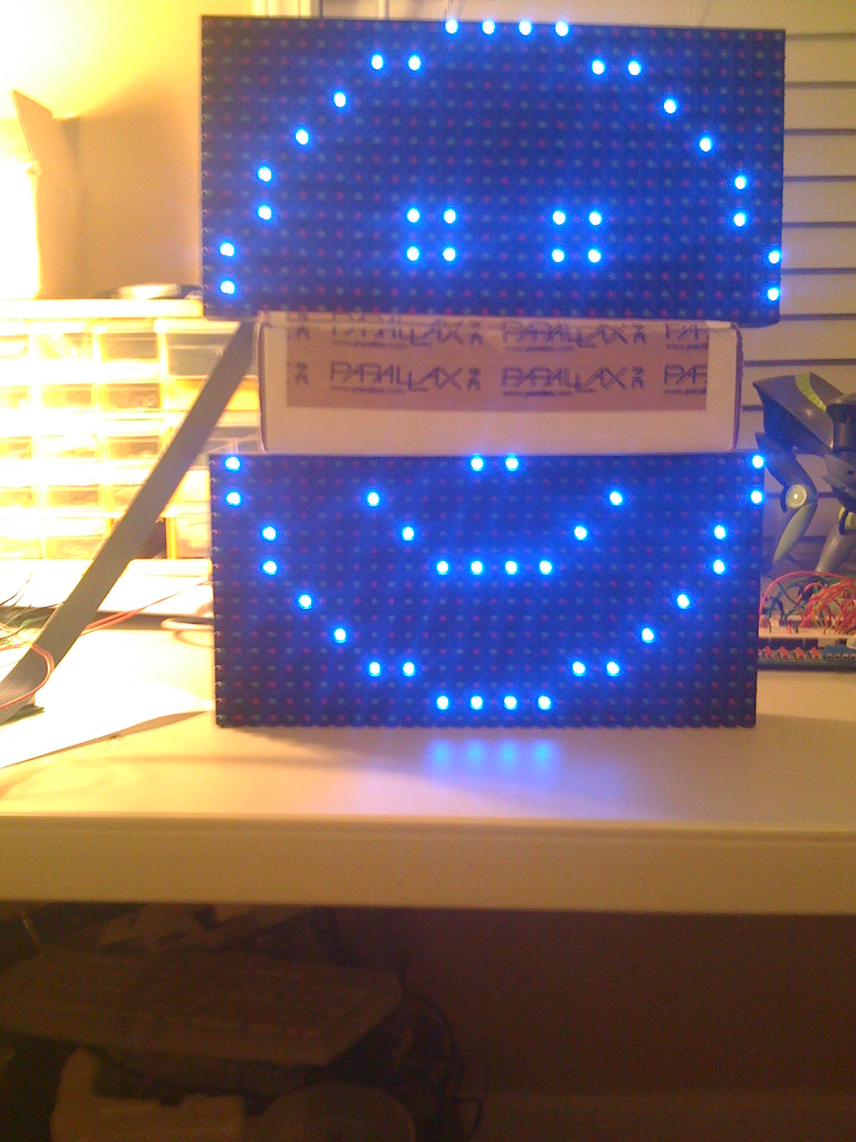
I have a program that works well at cycling through the 4 RGB LEDs on·a 16x8 module. Actually I have 2 of them cascaded so it's actually 16x16 (see the attached ZIP WMV movie).
Each module has 2 data streams (4 total between 2 modules). See the 2nd page of the attached datasheet to see the 2 data stream patterns per module. So each data stream controls 64 LEDs (either on or off) for each of the 4 RGB LEDs (e.g. Red, Red2 {virtual}, Green, Blue). So you could·shift out·a 64 bit data pattern to·turn on either Red, Red2, Green, or Blue LEDs (see attached SXB program). I have to use a Tile Calculator (attached in a ZIP) to put the pattern into the correct DATA statement format - and then COPY/PASTE it into the SX program (which is ok for now).
I want to take this to the next level and insert PWM (or 256 LED shades of Red, Red2, Green and / or Blue). However, first, I have never done this before but have read a few posts on the forum. Second, it appears that PWM may require a capacitor and resistor for each Red, Red2, Green and Blue input (for the·top and·bottom data streams) to the module. Is this right?
What I beleive is the biggest question can the SX (preferably the SX28 proto board -·but an SX48 proto board can be used if the SX28 can't) do PWM for an SPI type data stream input to 64 LEDs?
As you can see in the SXB program, the data is simply READ in and pushed out to both module's data streams. According to the data sheet, these modules can handle 256 gray shades so that is what led me to beleive it would work. However, after reading the forum posts on PWM, I am questioning it now.
Please me know if this is possible and how I might get started for a Newbie in PWM.
Thanks to all!
Post Edited By Moderator (Chris Savage (Parallax)) : 10/20/2008 3:04:04 PM GMT

1200 x 1600 - 394K
Comments
Everything I find on the web for PWM is PIC related and not SX. I really need·some help in figuring this PWM out - if it can even work with SPI.
I did see·on a PIC design that they used /OE for the·PWM line.·So it must be possible - but how·to do it on an SX chip.
Thanks.
▔▔▔▔▔▔▔▔▔▔▔▔▔▔▔▔▔▔▔▔▔▔▔▔
Tom Smykowski: Well-well look. I already told you: I deal with the customers so the engineers don't have to. I have people skills; I am good at dealing with people. Can't you understand that? What is wrong with you people?
The cascaded LED drivers (MBI5024GF) that are on the Absen-OF20V 16x8 RGB module acts like·cascaded '595 ICs with 16 outputs. In my previously attached SX28 code, you will see that I set /OE high initially (e.g. OE = 1), then after the data gets clocked, I set /OE low (e.g. OE = 0) all from the SX28 micro-controller.
Do I pulse out after the data gets clocked out? What does the·SX28 do to these pins? Is the PWM command really going to go to the /OE line - Isn't this for analog and /OE is digital (on or off)?
The problem I see with using /OE is that the 16x8 RGB module has·ALL of the /OE lines on·ALL of the cascaded MBI5024GF led drivers tied together. So this means that setting /OE high or low will affect ALL of the LED outputs not individual Red, Red2, Green, Blue LEDs to get 256 shades. Am I right about this?
There is no mention on any datasheet to say that the MBI5024GF has any PWM built in BUT the Absen-OF20V 16x8 RGB module (which has these cascaded MBI5024GF LED drivers) states in it's data sheet (previously attached) that the all the LEDs have 256 Greys which tells me that they are suposed to be able to do PWM "SOME HOW??" from the Absen-OF20V RGB modules with no PWM signal.
Also these Absen-OF20V 16x8 RGB modules are used in huge outdoor LED display signs with full 36 bit color. This again infers that PWM must be possible. However, these modules are cascaded by the 100's to form these huge outdoor signs. They are normally controlled by a custom PCI card with Ethernet and DVI for video input.
I am trying to find a way to basically re-create something on a simpler scale that can be controlled by a Parallax SX28 micro-controller and not by this card because the PC software is not that good. It will be connected to a PC at sometime, probably via Serial or (USB-to-Serial) to send the data from a custom software program - maybe Visual Basic. Im sure I could even use Hyperterminal today but will need something more robust on the PC. But thats for later. Todays question / concern is PWM possibility for individual RGB LED control using an SX chip·with this Absen-OF20V 16x8 RGB modules - cascaded a few dozen times.
Is this still possible? I hope·everyone can see my intentions.
Thanks for listening and your assistance.
Post Edited (T&E Engineer) : 10/19/2008 10:57:50 PM GMT
You want the square wave output from the PWM pin not an analog voltage so don't add a resistor and cap'. Drive the Output Enable inputs directly from the PWM pin. For example, setup your PWM period to 200 Hz and adjust the duty cycle from 255 (0% brightness, display off) to 0 (100% brightness). This affects the brightness of all four sets of LEDs being displayed. If you're trying to accomplish color control by displaying Blue LEDs at 25% brightness and Red LEDs at 50% brightness and Green LEDs at 40% brightness, the PWM mechanism is not going to do it for you without a major software driver overhaul.
Does this still look possible using the PWM command or is there "another" way short of doing this with a PIC chip?
Post Edited (T&E Engineer) : 10/20/2008 1:32:19 PM GMT
You will see a Full Color LED Display controller for the PC that controls this card. I am trying to interface directly with these modules so that we can bypass or perhaps come up with a similar PC card that is controlled with a micro-controller like the Parallax SX28 or SX48.
This installation manual link should provide more detail about how these modules work. On page 17 of 26, it shows a "Receiving Card" that all of these modules plug into which then goes to the Full Color LED Display Controller - once in the PC.
So this proves that only the pins on the input and output jacks are used and it can perform full color (WHICH MUST MEAN IT CAN DO "PWM" OF SOME SORT to get 36 Bit color resolution).
I am working on this as a test to see their capability with a micro-controller. I beleive PWM is possible after reading though all the SPECs and Data.
The only signals on each module are as follows:
R1A, R1B, R2A, R2B, G1, G2, B1, B2, CLK, LATCH, /OE, GND.
Somehow from these connections, PWM has to be possible.
Comments?
Post Edited (T&E Engineer) : 10/21/2008 12:06:06 AM GMT
Here is a simple irq routine that will run a single rgb led with 256x3 resolution.
org $0
interrupt
    bank $10

    incsz dutyt
    jmp red            ;if cycle not over test rgb timmers
    incsz dtime
    setb moveon           ;just a delay pointer for my latter doing color sweeps
    setb ledred        ;reset rgb pins assume not equal zero
    setb ledblue
    setb ledgreen
red
    jnb ledred, blue    ;move on if already off
    csne redt, dutyt    ;is this the end of on cycle
    clrb ledred         ; if yes, turn off red led
blue
    jnb ledblue, green
    csne bluet, dutyt
    clrb ledblue
green
    jnb ledgreen, endirq
    csne greent, dutyt
    clrb ledgreen
endirq
    mov w, #-75
    retiw
I've included a little demo program that cycles through some colors. I'm not sure this will help you with your led matrix isssue. It will probably work better if you pick a smaller resolution.
I believe this is possible for a configuration like this. However, what I am doing is shifting data through dozens or hundreds of RGB LEDs through an SPI like interface chip. It is very similar to a 74HC595 that many people on this forum are familiar with. This is what I am not getting any answers to here or elsewhere. I am very happy for peoples input to help but perhaps I am asking something that has not been done before with an SX chip. Other PIC chips have PWM modules built into them while the SX does not except for an analog based PWM command. I don't think I can apply an analog signal to a digital circuit such as /OE to enable the PWM feature in this way. I need squarewaves not sinewaves I beleive for PWM from what I have learned on another PIC forum.
This and the other forum has not provided me with much if any information on whether PWM can be performed on an SPI design like this.
Thank you for your efforts and help. I hope that I can get some answers to my question soon on this forum and/or the PIC forum.
Thank you JonnyMac.
Summary: For 256 levels you need to latch 256 different ON / OFF states for a single LED in the same amount of time. Note that the data rate must be 255 times higher, which can be hard to do via bit-banging in software.
A refresh routine something like this might work (pseudo C):
#define BRIGHTNESS_BITS 8
#define BRIGHTNESS_LEVELS (1 << BRIGHTNESS_BITS)

#define LED_OFF 1
#define LED_ON 0

void refresh(void)
{
    int red;
    int green;
    int blue;
    int row;
    int column;
    int b;

    for (row = 0; row < ROWS; row++) {
        for (b = 1; b < BRIGHTNESS_LEVELS; b++) {
            for (column = 0; column < COLUMNS; column++) {
                if b > Red brightness level of LED[noparse][[/noparse]row][noparse][[/noparse]column] {
                    red = LED_OFF;
                } else {
                    red = LED_ON;
                }
                if b > Green brightness level of LED[noparse][[/noparse]row][noparse][[/noparse]column] {
                    green = LED_OFF;
                } else {
                    green = LED_ON;
                }
                if b > Blue brightness level of LED[noparse][[/noparse]row][noparse][[/noparse]column] {
                    blue = LED_OFF;
                } else {
                    blue = LED_ON;
                }
                Shift out red, green, and blue data.
            }
            Latch row data
            Turn on LED power for Row
            Delay until next brightness period
        }
        Delay until next row period
        Turn off LED power
    }
}
For SPI, you will likely need 3 ports if red / green / blue share the same clock. Set blue to master, and red and green to slave. Write slave data first, then master data to start the shifter. With separate clocks for each, only one SPI port is needed, but then timing is tighter because of having to shift in 1/3 the time. The code is the same for SPI, except gather up 8 bits of data per color (if (column & 7) == 7) before shifting it out via SPI.
Post Edited (Andrew E Mileski) : 11/7/2008 12:10:26 AM GMT
I thank you for your PWM concept of possibility. However, I am not all following what you are saying. How does the calculations for frequency play into this.
All I am doing is what you would do for like any SPI device (e.g. 74HC595), Set the Red, Green or Blue data up with some value, clock the data out and when ready latch it. This is repeated over and over. I don't follow how this is done 256 times for red, 256 time for green and 256 times for blue with a single clock and latch. How does /OE play into this if it controls ALL of the SPI chips? Since the "single" clock line can be set to 20 nS (according to the MBI5024 data sheet), are there delays put in to ensure this? Could you break this down into how each of the RED, GREEN and BLUE data could get 256 shades of each?
Thanks for your help.
It's getting better for me but take a look at the datasheets. This RGB 16x8 pixel module uses cascaded SPI chips (like a 16 LED output version of 74HC595's - if it existed) Each module has 2 data streams (upper 8 rows and lower 8 rows) - in sort of a zig zag shifting out method (see bottom of page 2 - attached). Each data stream can shift out 64 bits of LED data for each color (Red, Green, Blue and Red2) for EACH of the 2 data streams.·The only connections going in and out of the modules that I have to work with is:
1. Clock
2. Latch
3. /Output Enable
4. Red LED Upper 64 bit Data
5. Red LED Lower 64 bit Data
6. Green LED Upper 64 bit Data
7. Green LED Lower 64 bit Data
8. Blue LED Upper 64 bit Data
9. Blue LED Lower 64 bit Data
10. Red2 LED Upper 64 bit Data
11. Red2 LED Lower 64 bit Data
12. Ground
There are no "rows" to deal with - just 2 separate datastreams. This is one item that is confusing to me in your write up.
I'm not sure what the "refresh" rate is for this board or if it even applies.
You can simplify this by thinking of a 16x8 module·as:
(2) 74HC595 chips with 64 RED LED outputs.
(2) 74HC595 chips with 64·GREEN LED outputs.
(2) 74HC595 chips with 64·BLUE LED outputs.
(2) 74HC595 chips with 64 RED2 LED outputs.
AND ALL OF THESE SHARE THE SAME CLOCK, LATCH and·/OE·LINES.
AND - dozens of these 16x8 modules can be daisy chained together
so 2 of them daisy chained together would look like:
(2) 74HC595 chips with·128 RED LED outputs.
(2) 74HC595 chips with·128·GREEN LED outputs.
(2) 74HC595 chips with·128·BLUE LED outputs.
(2) 74HC595 chips with 128·RED2 LED outputs.
so 3 of them daisy chained together would look like:
(2) 74HC595 chips with·192 RED LED outputs.
(2) 74HC595 chips with·192·GREEN LED outputs.
(2) 74HC595 chips with·192·BLUE LED outputs.
(2) 74HC595 chips with 192·RED2 LED outputs.
Does this make sense? I hope so as I need to know how I can adapt this for PWM.
Thanks so much for your help.
You need a microcontroller with an on-chip SPI port (or build one from discrete logic). This is like a 74HC165 with a small difference:
- Writing to a SPI master port latches the data and starts a counter to clock out 8 data bits and then stops. (It also clocks in 8 bits of data from a slave.)
- Writing to a SPI slave port just latches the data. (It is up to the master to clock it in.)
Most SPI controllers are not buffered, so you have to wait for the data to go out before writing more. There is usually a status register with a DONE flag that can be polled for a busy-wait, or you can just wait the calculated 8 bit time.
Why an on-chip SPI controller? Because it is at least 10 times faster than bit-banging an output port.
Interesting datasheet. The display is RRGB not RGB. It's not a matrix either.
You already know how to use the display. You are already using it with 1 bit of luminance (ON-OFF). All you need to do is to change the data every refresh, and refresh it faster. The code I posted (though for a matrix, you can substitute 2 rows and 64 columns) outputs the PWM data you need.
Start small. Try 2 bits of luminance. Refresh the display faster, say 3 x 70 Hz = 210 Hz. If bit-banging, divide delays by 3.
Luminance Value: Data to shift out least significant bit first
00: 000
01: 001
10: 011
11: 111
For a luminance value of 2:
First Refresh: Turn the LED on
Second Refresh: Turn the LED on
Third Refresh: Turn the LED off
Note that you can either refresh 3 times faster like this:
- First Refresh Top, First Refresh Bottom
- Second Refresh Top, Second Refresh Bottom
- Third Refresh Top, Third Refresh Bottom
Or like this:
- First Refresh Top, Second Refresh Top, Third Refresh Top
- First Refresh Bottom, Second Refresh Bottom, Third Refresh Bottom
The latter has the advantage of keeping LEDs on longer continuously, resulting in a brighter display (well, on a true matrix at least).
Post Edited (Andrew E Mileski) : 11/7/2008 9:09:07 PM GMT
The code works as follows:
0. Disable the display.
1. READ in·1 byte (8 bits) for the upper data stream.
2. READ in·1 byte (8 bits) for the lower data stream.
3. The SPI routine is called that clocks out the 1 byte of upper data
4. The SPI routine also clocks out·1 byte of lower data.
5. READ in the next byte for the upper data stream.
6. READ in the next byte for the lower data stream.
7. Repeat process·until 64 bits (8 bytes)·of Red data are clocked out to the upper rows of the display.
8. Repeat process·until 64 bits (8 bytes)·of Red data are clocked out to the·lower rows of the display.
9.·Enable the display.
10. Latch the·data streams·out.
11. Pause a few micro seconds to give the LEDs time to turn on a display light.
12. Repeat and loop·the process with the same 64 bits of upper and lower data back into the display again
Is step 12 the refresh???
Thanks.
' =========================================================================
'   Authors... Timothy Gilmore
'   File...... Absen-OF20V_v1.sxb
'   Purpose... Use with Absen OF20V 16x8 2RGB module.
'
' =========================================================================
' -------------------------------------------------------------------------
' Program Description
' -------------------------------------------------------------------------
' Program code to use ....

' -------------------------------------------------------------------------
' Device Settings
' -------------------------------------------------------------------------

DEVICE sx28, oschs2, TURBO, STACKX, OPTIONX
FREQ  20_000_000

' -------------------------------------------------------------------------
' IO Pins
' -------------------------------------------------------------------------

CL  PIN RA.0 OUTPUT 'J1-9
ST  PIN RA.1 OUTPUT 'J1-11
OE  PIN RA.2 OUTPUT 'J1-13
R1A  PIN RB.0 OUTPUT 'J1-1
R1B  PIN RB.1 OUTPUT 'J1-2
G1  PIN RB.2 OUTPUT 'J1-3
B1  PIN RB.3 OUTPUT 'J1-4
R2A  PIN RB.4 OUTPUT 'J1-5
R2B  PIN RB.5 OUTPUT 'J1-6
G2  PIN RB.6 OUTPUT 'J1-7
B2  PIN RB.7 OUTPUT 'J1-8

' -------------------------------------------------------------------------
' Constants
' -------------------------------------------------------------------------


' -------------------------------------------------------------------------
' Variables
' -------------------------------------------------------------------------
pos          VAR  Byte
slice        VAR  Byte
bitmask      VAR  Byte
info_bit_R1A VAR  Byte
info_bit_R2A VAR  Byte
data_bit_R1A VAR  Byte
data_bit_R2A VAR  Byte
alpha        VAR  Byte

' =========================================================================
  PROGRAM Start
' =========================================================================
' -------------------------------------------------------------------------
' Subroutine Declarations
' -------------------------------------------------------------------------
ST_see         SUB  0
SPI            SUB  0

' -------------------------------------------------------------------------
' Program Code
' -------------------------------------------------------------------------
Start:
Displays:
    OE = 1 'Disable display for setup
    FOR alpha = 0 TO 7    ' progress through letters in DATA "message"
      pos = alpha
      READ fig_R1A + pos, data_bit_R1A
      READ fig_R2A + pos, data_bit_R2A
      SPI
    NEXT alpha
      ST_see
GOTO Displays
' -------------------------------------------------------------------------
' Subroutine Code
' -------------------------------------------------------------------------

SUB SPI
  ' ---- SPI Begins! ----
  bitmask = $80
  RB = RB | %00010001
  FOR slice = 1 TO 8
    info_bit_R1A = data_bit_R1A & bitmask  ' 0 or bitmask
    info_bit_R1A = info_bit_R1A MAX 1      ' info_bit_R1A / bitmask      ' 0 or 1
    info_bit_R2A = data_bit_R2A & bitmask  ' 0 or bitmask
    info_bit_R2A = info_bit_R2A MAX 1      ' info_bit_R2A / bitmask      ' 0 or 1
        R2A = info_bit_R2A
        R1A = info_bit_R1A
  ' the RB bits have been set, ready to pulse clock for external latch
      CL = 1  'Clock pulse
      CL = 0  'Clock pulse
      bitmask = bitmask SHR 1   ' 0_$80, 1_$40, 2_$20, 3_$10, 4_$08, 5_$04, 6_$02, 7_$01, 8_$0...
      NEXT slice
ENDSUB
SUB ST_see   ' latch data, enable line
    ST = 1   ' bop ST
    ST = 0   ' bop ST
    OE = 0   ' Enable Display
    PAUSEUS 100
ENDSUB


' ---------- Display DATA ---------
fig_R1A: 'Hidden Message TOP
DATA %01000100, %10001000, %00110100, %10000001, %11000010, %00011000, %00100010, %00010001
fig_R2A: 'Hidden Message BOTTOM
DATA %00000000, %00010010, %00111100, %00000000, %11000011, %00000000, %00000000, %10000100
·
Well 1 to 11 is the refresh, 12 repeats it with the same data. I don't understand why you have that.
I'd recommend storing pixel data differently if possible. I'm betting that you are currently using pixel packing with 8 pixels per byte, which makes sense with 1 bit of luminance but is awkward with more.
Byte offset 0: pixel 0, red
Byte offset 1: pixel 0, green
Byte offset 2: pixel 0, blue
Byte offset 3: pixel 1, red
Byte offset 4: pixel 1, green
Byte offset 5: pixel 1, blue
...
This makes it so that you can use:
Next pixel offset = current pixel offset + 3
Red = current pixel offset + 0
Green = current pixel offset + 1
Blue = current pixel offset + 2
Then all you need to do is to keep track which field you are on, convert the the 3 byte RGB value to 3 PWM bits for that field, shift the bits out
/* Field ranges from 1 to 2^luminance bits - 1 */
int rgb_to_pwm(int field, int red, int green, int blue)
{
    int retval = 0;
    retval |=  (field > red) ? LED_OFF: LED_ON;
    retval <<= 1;
    retval |=  (field > green) ? LED_OFF: LED_ON;
    retval <<= 1;
    retval |=  (field > blue) ? LED_OFF: LED_ON;
    return retval;
}
Post Edited (Andrew E Mileski) : 11/7/2008 10:58:04 PM GMT
This requires that:
1) Power to the LED must be on.
2) The LED state is latched.
Latching the LED state can be done at a much higher rate than turning the power OFF and ON.*1 This makes it possible to turn the power ON and latch different PWM state for the LED while leaving the power ON.
Ideally only turn the power OFF when leaving it ON would result in a LED displaying the wrong state, which only happens in a device with multiple rows where only one row can be powered at a time.
Most 74HC parts are guaranteed to operate at 30 MHz (33 ns), and have a max limit of 50 MHz (20 ns). The actual limit really depends on the manufacturer, and where in the silicon wafer the chip was cut from, hence the wide range.
*1 This largely has to do with the time it takes for the voltage to ramp up because of capacitance in the power circuitry, as well as the response time of the power supply to a sudden increased load. Some boards also have RC circuits to limit the ON time because they overdrive the LEDs for more brightness.
Post Edited (Andrew E Mileski) : 11/8/2008 7:38:44 PM GMT