Please, please stop modifying parts of a setup that you are not sure if it's working. I've told this my customers so many times...
If you are working on something new which has never worked before or that you are not familiar with, make sure to start with a system that consits exclusively of parts that you can be sure they are working.
Buy a new eval board
Buy a new ProgPlug
Download a simple demo program
Then test it
If you are successful with that you can add other things step by step. If it stops working at some point, go back one step and it should be fine, again.
Trying out fixes by guessing with a system that can suffer from multiple problems is a lottery with only very small chances. Even if you fix one thing by good luck you may not notice because the other thing might still be broken.
If a ProgPlug works with the P1 that's no guaratee that it still does with the P2. I have some here with the same symptoms.
I would be curious what the results of the following program's debug would be. Please upload to RAM with debug enabled and post back the results.
'' =============================================================================
''  BootPinConfig.spin2
''
''  Reads the Parallax P2 Edge (#P2-EC) boot-configuration DIP switches and
''  prints the decoded configuration to the DEBUG terminal.
''
''  The P2 Edge has a 4-position DIP switch. Each position simply adds a weak
''  (~100 k) pull resistor to one of the SPI-boot pins, or enables the LEDs:
''
''     Switch   Effect
''     ------   ------------------------------------------------------------
''     LED      Connects the on-board LEDs (P56 / P57) to their buffers.
''     FLASH    Pull-UP   on P61  -> boot ROM tries the on-board SPI flash.
''     up (^)   Pull-UP   on P60  -> boot ROM tries an SD card.
''     down (v) Pull-DOWN on P59  -> boot ROM SKIPS the serial-boot window.
''
''  Because the switches are only pull resistors on the flash SPI pins, a
''  running program can sense them by floating P59/P60/P61 and reading the
''  level the pull resistor settles them to. The flash chip's CLK/CS/DI lines
''  are high-impedance inputs while idle, so they don't fight the read.
''
''  Caveat: an OFF switch leaves its pin with no pull, so the reading depends
''  on the pin floating to a stable level. For a guaranteed result you would
''  measure RC decay instead; see notes at the bottom of this file. The LED
''  switch is not sensed here (it gates the LED buffers, not a readable pin) --
''  observe the LEDs to confirm it.
'' =============================================================================

CON
  _clkfreq = 200_000_000             ' P2 Edge 20 MHz crystal -> 200 MHz via PLL

  FLASH_PIN = 61                     ' pull-up   = SPI flash boot
  SD_PIN    = 60                     ' pull-up   = SD card boot
  SER_PIN   = 59                     ' pull-down = skip serial boot

PUB main() | flash, sd, ser

  ' Float the three boot-mode pins (input, no internal pull) so we sense only
  ' the switch pull resistors, then allow a couple ms for them to settle.
  pinf(SER_PIN addpins 2)            ' P59, P60, P61 -> input / floating
  waitms(2)

  flash := pinr(FLASH_PIN)
  sd    := pinr(SD_PIN)
  ser   := pinr(SER_PIN)

  debug(" ")
  debug("=== P2 Edge boot DIP switch configuration ===")
  debug(" ")
  debug("Raw boot pins:  P61=", udec_(flash), "  P60=", udec_(sd), "  P59=", udec_(ser))
  debug(" ")

  if flash
    debug("FLASH  (P61 pull-up)   : ON   -> SPI flash boot enabled")
  else
    debug("FLASH  (P61 pull-up)   : off  -> SPI flash boot disabled")

  if sd
    debug("up ^   (P60 pull-up)   : ON   -> SD card boot enabled")
  else
    debug("up ^   (P60 pull-up)   : off  -> SD card boot disabled")

  if ser
    debug("down v (P59 pull-down)  : off  -> serial-boot window ALLOWED")
  else
    debug("down v (P59 pull-down)  : ON   -> serial-boot window SKIPPED")

  debug(" ")
  debug("LED switch: not sensed in software -- check the P56/P57 LEDs.")
  debug(" ")
  debug("Resulting boot order:")
  print_boot_order(flash, sd, ser)

  repeat                             ' park

PRI print_boot_order(flash, sd, ser)

  ' The P2 boot ROM walks flash -> SD -> serial, taking the first one its
  ' pull resistors enable. A pull-down on P59 removes the serial fallback.
  if flash
    debug("  1) SPI flash (P61)")
  if sd
    debug("  2) SD card  (P60)")
  if ser
    debug("  3) Serial / monitor window")
  else
    debug("  (serial window skipped by P59 pull-down)")

  if not (flash or sd or ser)
    debug("  No boot source selected -- check the switches.")
@ke4pjw said:
I would be curious what the results of the following program's debug would be. Please upload to RAM with debug enabled and post back the results.
Also, yeah, that sounds like the programmer is operating on an Edge case. With the repeating debug info from the top of the program sounds like it may be loading the reset circuit, maybe? Have you scoped it?
@ke4pjw said:
Also, yeah, that sounds like the programmer is operating on an Edge case. With the repeating debug info from the top of the program sounds like it may be loading the reset circuit, maybe? Have you scoped it?
I did not.
Thanks for the hint, I will try next week, I do not have access to an oscilloscope now
@"Andrey Demenev" said:
Interestingly, if I insert a small delay before each debug() call, the output is this, which is exactly as expected:
One thing I forgot about is that the board has 19.2 MHz crystal (I added _xtlfreq = 19200000 to the code)
Okay, then try this without the added delays. You'll need to adjust the terminal baud to match:
CON
    _xtlfreq = 19_200_000
    _clkfreq = 4_000_000
    DEBUG_BAUD = 19200
And if that works then try removing either _clkfreq or DEBUG_BAUD (reverting the terminal here) to see which one matters.
Without DEBUG_BAUD debug output is always nonsense. With DEBUG_BAUD, the debug output is fine, regardless of _clkfreq (tried from 1MHz to 320 MHz), but only if DEBUG_BAUD has a "standard" value (9600, 19200, 38400 etc) up to 230400. 460800 produces no debug output. 2000000 produces the same nonsense output I posted above (I believe 2 Mbaud is the default)
@"Andrey Demenev" Just a couple of observations. The prop plug uses the FT231 with a open collector NPN transistor that connects to the RST line.
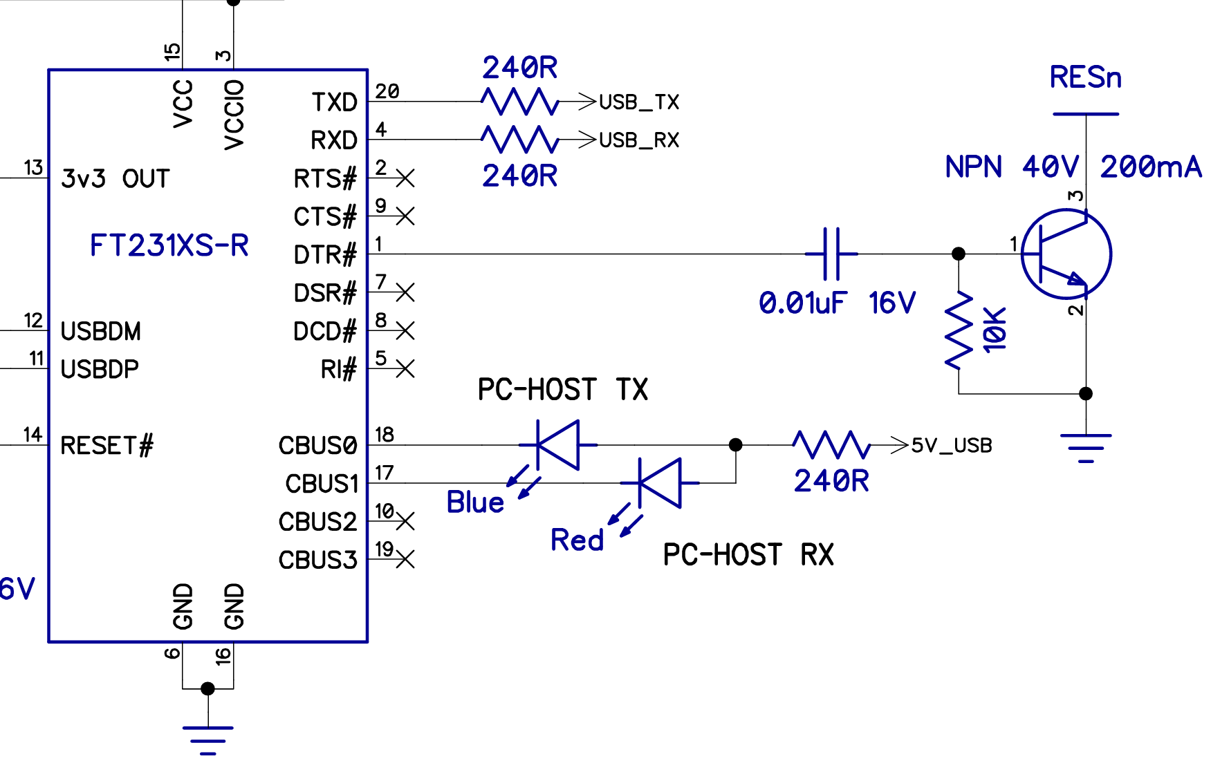
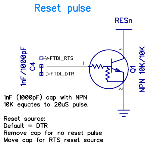
The FT232 should be capable of 2Mbaud, but your reset configuration might be problematic, as there is an existing 10K pullup on the edge. With the additional 3.3K above ground, it may not drop the voltage low enough, fast enough, to properly reset.
Rev D Prop Plug
Rev E Prop Plug
Rev E uses an OnSemi MUN5211T1G as the transistor.
The FT232 should be capable of 2Mbaud, but your reset configuration might be problematic, as there is an existing 10K pullup on the edge. With the additional 3.3K above ground, it may not drop the voltage low enough, fast enough, to properly reset.
I will have a chance to use an oscilloscope in a couple of days, I'll see what's going on there
@"Andrey Demenev" In the other Thread, you said you figured it out and got some code running. Congratulations...
But could you please tell us what was the cause of the problem? It may help somebody else to know the solution.
@ManAtWork I do not have a solution. I am still using the simple adapter with just a capacitor from DTR to reset, without a transistor, and it works for me somehow
Tomorrow I will go to a local hackerspace where we have an oscilloscope and computers with different OSes. I will compare my 2 adapters and examine the difference in reset signal, and also see if the issue I was observing is OS specific
I think the downloaders have been optimised early on for Eval boards, which uses the FT323 direct drive (non-inverted) wiring. And later boards using the Propplug became second citizens. Edge Cards have probably had oddball download issues all along. It'll depend on which downloader. Which downloaders have you tried so far?
@evanh said:
I think the downloaders have been optimised early on for Eval boards, which uses the FT323 direct drive (non-inverted) wiring. And later boards using the Propplug became second citizens. Edge Cards have probably had oddball download issues all along.
If that is true, than there's nothing wrong with my setup
It'll depend on which downloader. Which downloaders have you tried so far?
So far I tried Spin Tools and flexprop, both behave identically
@"Andrey Demenev" said:
So far I tried Spin Tools and flexprop, both behave identically
Few posts above I suggested to upload with the terminal window open, have you tried that ?
It may give an hint if the reset occurs because the serial port is closed after the upload.
BTW, I only have prop-plugs, never had an Eval board, however they are one of the first modules (not the latest rev. E with a slightly different reset circuit) so I don't know if there are issues with the latest rev. E prop-plug.
@"Andrey Demenev" said:
So far I tried Spin Tools and flexprop, both behave identically
Few posts above I suggested to upload with the terminal window open, have you tried that ?
It may give an hint if the reset occurs because the serial port is closed after the upload.
Yes, I tried that. When terminal is open, upload to both RAM and flash works fine.
@"Andrey Demenev" said:
So far I tried Spin Tools and flexprop, both behave identically
Few posts above I suggested to upload with the terminal window open, have you tried that ?
It may give an hint if the reset occurs because the serial port is closed after the upload.
Yes, I tried that. When terminal is open, upload to both RAM and flash works fine.
Good, this means that the reset is triggered by closing the port, almost certainly because dtr is in the opposite state.
Wondering if the fix is the same as Windows, unfortunately I don't have a Mac to test (if I'm not wrong, from the screenshots, you are using a Mac).
@evanh said:
I think the downloaders have been optimised early on for Eval boards, which uses the FT323 direct drive (non-inverted) wiring. And later boards using the Propplug became second citizens. Edge Cards have probably had oddball download issues all along.
I have a number of boards that (under Linux with loadp2) reset when the port is closed. IIRC there's a Linux kernel issue where the flow control signals change when the port is closed that doesn't exist on WinNT (this has been discussed before!). I'd have to dig them all out again to test, but IIRC the EVAL is one of the few that works correctly.
@evanh said:
I think the downloaders have been optimised early on for Eval boards, which uses the FT323 direct drive (non-inverted) wiring. And later boards using the Propplug became second citizens. Edge Cards have probably had oddball download issues all along.
I have a number of boards that (under Linux with loadp2) reset when the port is closed. IIRC there's a Linux kernel issue where the flow control signals change when the port is closed that doesn't exist on WinNT (this has been discussed before!). I'd have to dig them all out again to test, but IIRC the EVAL is one of the few that works correctly.
That made me think that I did something in my Linux setup to prevent the reset on port close, and indeed I found this udev rule (added 5-6 years ago and forgot...):
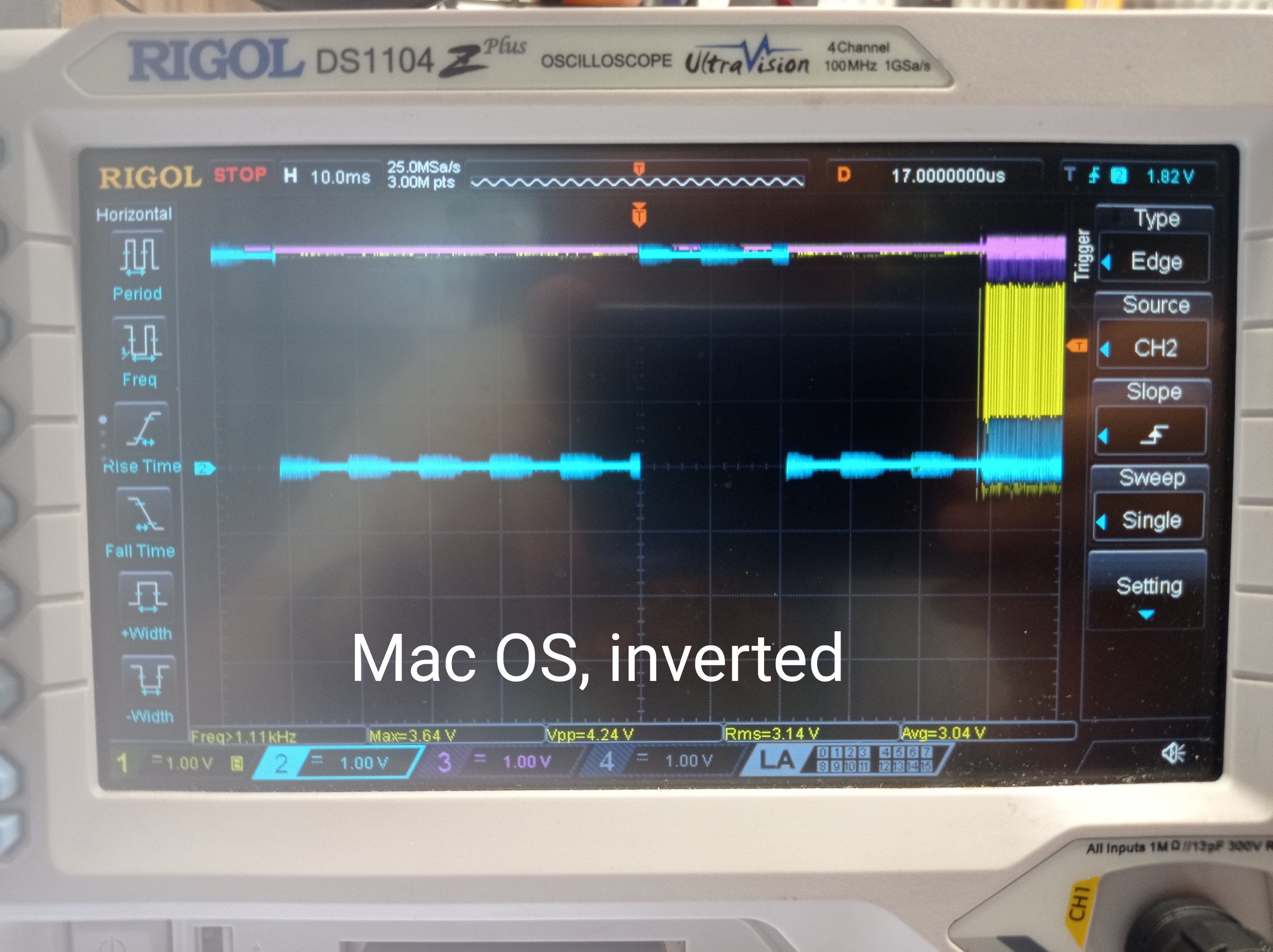
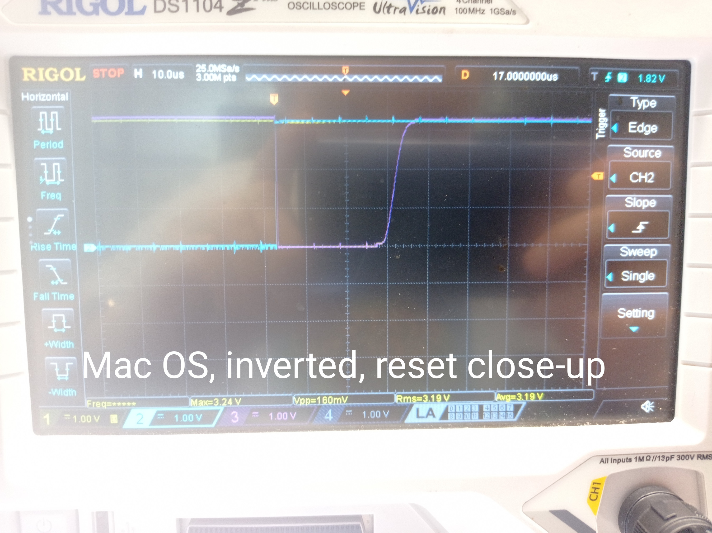
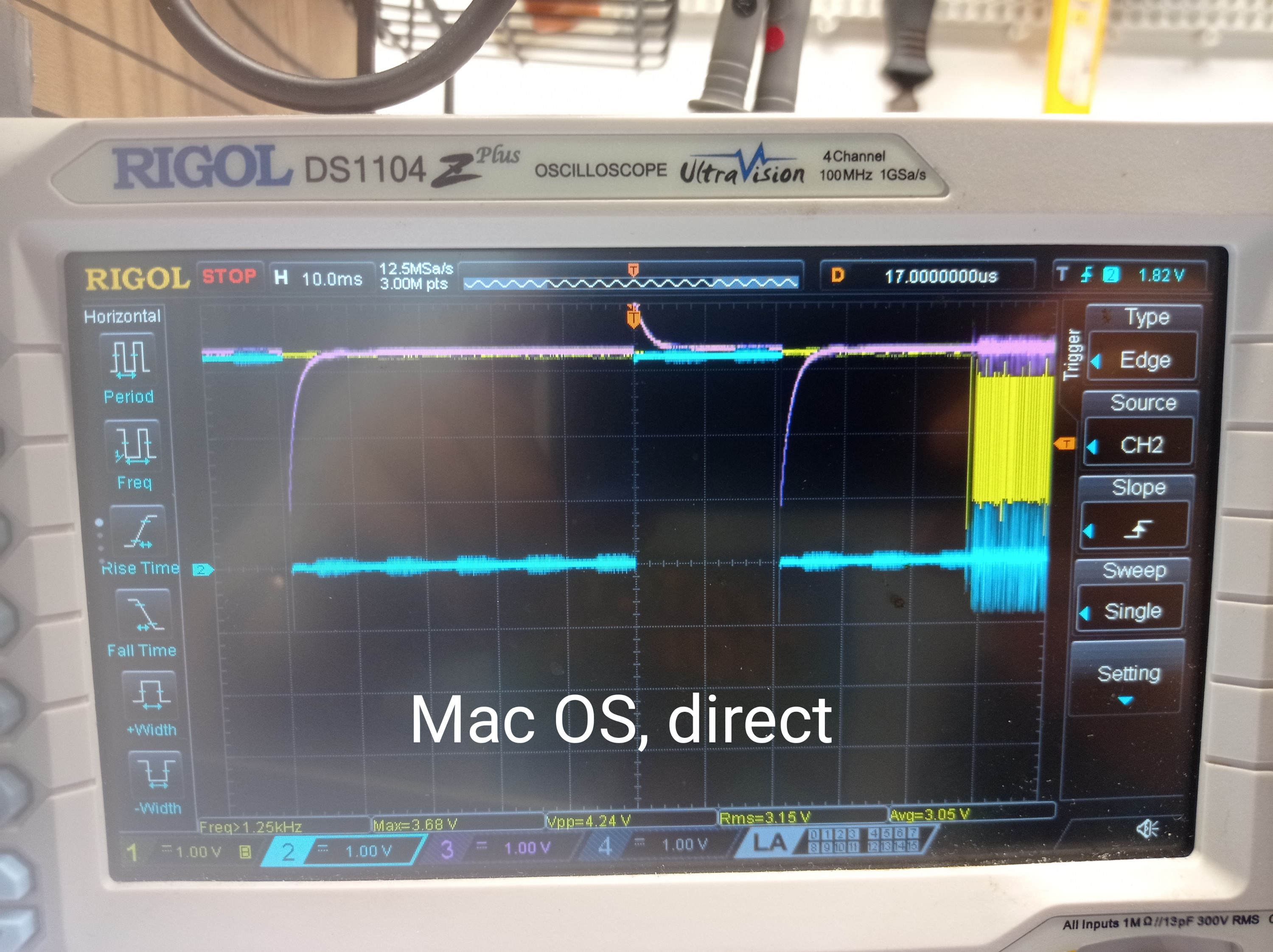
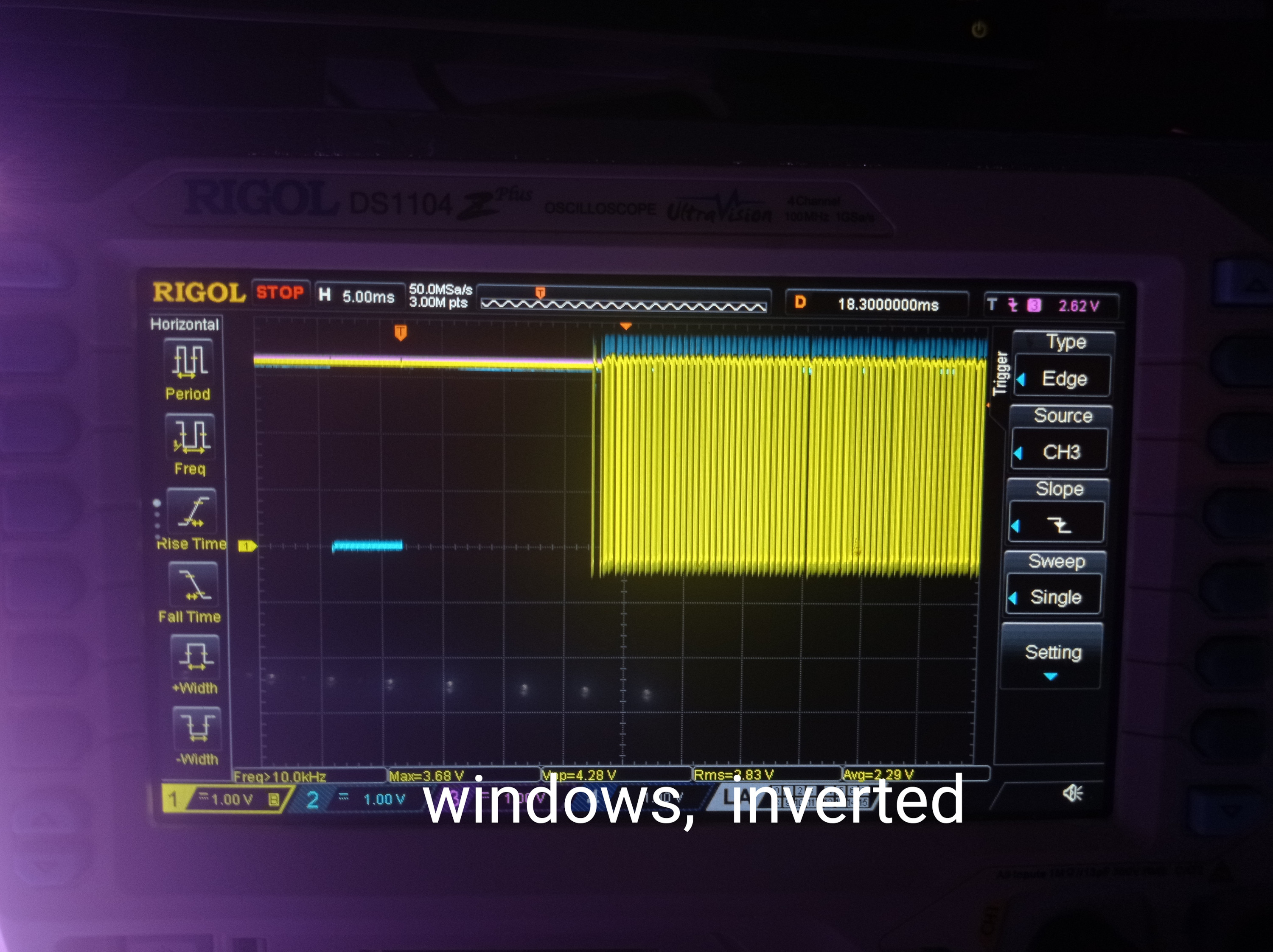
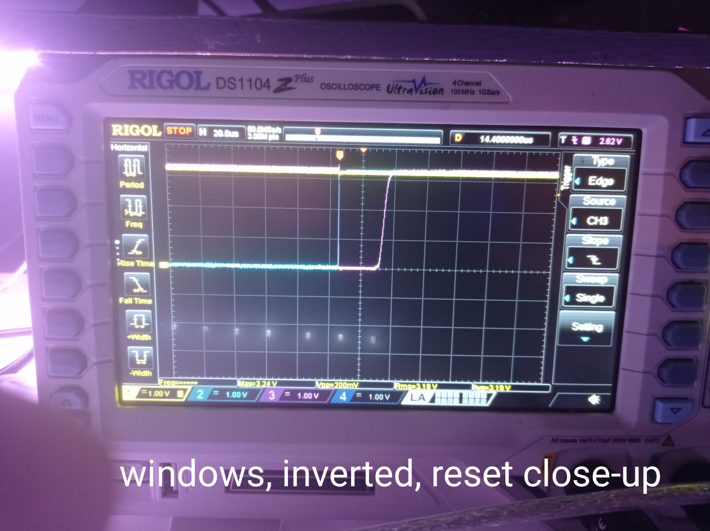
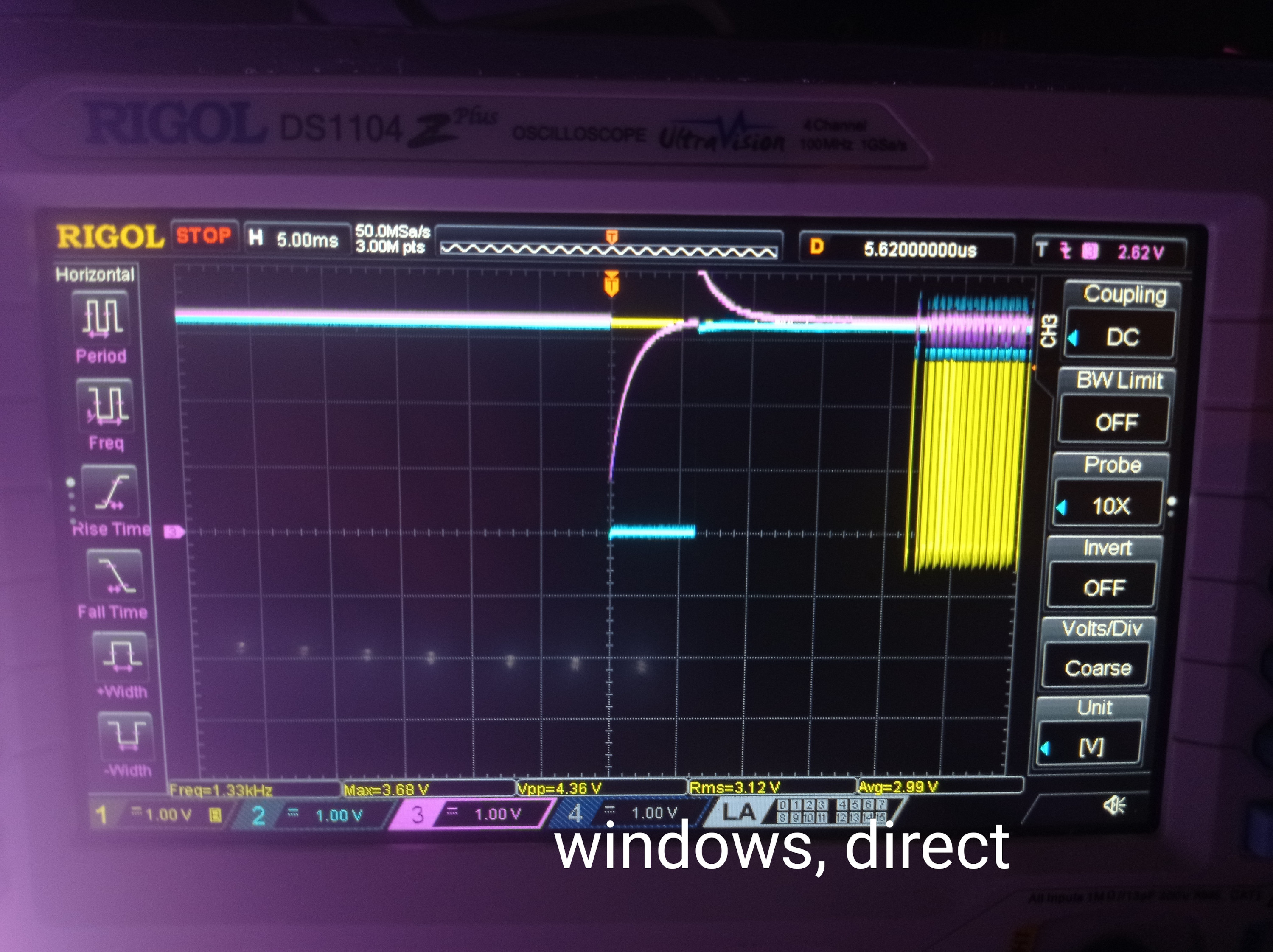
I tried Spin Tolls on Windows and Mac OS (and Linux). Linux and Mac OS behave exactly the same, direct dtr connection to reset (via a cap) gets program uploaded in all modes. Inverted DTR only works when terminal is open, or with debug.
Windows is more interesting. It works with both adapters, direct and inverted, in all modes. Attached are some oscillograms. Quality is not the best, but I think it is clear what is going on there. Under windows, DTR is "normally" high and under linux it is low. That's the only difference, and it makes all the difference. I think that special check in Spin Tools source should be removed, and control signals must be used as in current Windows version
@"Andrey Demenev" said:
I tried Spin Tolls on Windows and Mac OS (and Linux). Linux and Mac OS behave exactly the same, direct dtr connection to reset (via a cap) gets program uploaded in all modes. Inverted DTR only works when terminal is open, or with debug.
Windows is more interesting. It works with both adapters, direct and inverted, in all modes. Attached are some oscillograms. Quality is not the best, but I think it is clear what is going on there. Under windows, DTR is "normally" high and under linux it is low. That's the only difference, and it makes all the difference. I think that special check in Spin Tools source should be removed, and control signals must be used as in current Windows version
On Linux I forgot to have a udev rule that prevents the dtr toggle on port close, try to run this command before uploading:
/bin/stty -F /dev/ttyUSB0 -hupcl
On MacOS, if the AI answers are correct, you have stty, try to the same command with the appropriate device name.
Windows is another beast, the trick works but is not correct.
On MacOS, if the AI answers are correct, you have stty, try to the same command with the appropriate device name.
Yes, that's correct, but that command works only when the port is open, as soon as there no processes that have that file open, the options are reset to default
@"Andrey Demenev" said:
Yes, that's correct, but that command works only when the port is open, as soon as there no processes that have that file open, the options are reset to default
Ah... too bad...
I could keep the port open, however this will be problematic for external programs.
I could launch stty just after opening the port, I'm not very inclined to launch a program without user explicitly configuring it, so this will require a specific configuration option, and I don't know what happens when the port is closed (it will still drop dtr or it is kept as is ?).
Not sure there is a solution, other than keep the terminal open.
The AI suggested doing
cat < /dev/cu.YOUR_PORT_NAME &
Then running your stty command. Apparently multiple applications can access the serial port at the same time and that will keep the configuration after closing the programming plug from the development tool.
I recall having a similar problem in windows. If I didn't want to reset the P2 I just unplugged the propplug from the P2.


Comments
Please, please stop modifying parts of a setup that you are not sure if it's working. I've told this my customers so many times...
If you are working on something new which has never worked before or that you are not familiar with, make sure to start with a system that consits exclusively of parts that you can be sure they are working.
If you are successful with that you can add other things step by step. If it stops working at some point, go back one step and it should be fine, again.
Trying out fixes by guessing with a system that can suffer from multiple problems is a lottery with only very small chances. Even if you fix one thing by good luck you may not notice because the other thing might still be broken.
If a ProgPlug works with the P1 that's no guaratee that it still does with the P2. I have some here with the same symptoms.
I would be curious what the results of the following program's debug would be. Please upload to RAM with debug enabled and post back the results.
'' ============================================================================= '' BootPinConfig.spin2 '' '' Reads the Parallax P2 Edge (#P2-EC) boot-configuration DIP switches and '' prints the decoded configuration to the DEBUG terminal. '' '' The P2 Edge has a 4-position DIP switch. Each position simply adds a weak '' (~100 k) pull resistor to one of the SPI-boot pins, or enables the LEDs: '' '' Switch Effect '' ------ ------------------------------------------------------------ '' LED Connects the on-board LEDs (P56 / P57) to their buffers. '' FLASH Pull-UP on P61 -> boot ROM tries the on-board SPI flash. '' up (^) Pull-UP on P60 -> boot ROM tries an SD card. '' down (v) Pull-DOWN on P59 -> boot ROM SKIPS the serial-boot window. '' '' Because the switches are only pull resistors on the flash SPI pins, a '' running program can sense them by floating P59/P60/P61 and reading the '' level the pull resistor settles them to. The flash chip's CLK/CS/DI lines '' are high-impedance inputs while idle, so they don't fight the read. '' '' Caveat: an OFF switch leaves its pin with no pull, so the reading depends '' on the pin floating to a stable level. For a guaranteed result you would '' measure RC decay instead; see notes at the bottom of this file. The LED '' switch is not sensed here (it gates the LED buffers, not a readable pin) -- '' observe the LEDs to confirm it. '' ============================================================================= CON _clkfreq = 200_000_000 ' P2 Edge 20 MHz crystal -> 200 MHz via PLL FLASH_PIN = 61 ' pull-up = SPI flash boot SD_PIN = 60 ' pull-up = SD card boot SER_PIN = 59 ' pull-down = skip serial boot PUB main() | flash, sd, ser ' Float the three boot-mode pins (input, no internal pull) so we sense only ' the switch pull resistors, then allow a couple ms for them to settle. pinf(SER_PIN addpins 2) ' P59, P60, P61 -> input / floating waitms(2) flash := pinr(FLASH_PIN) sd := pinr(SD_PIN) ser := pinr(SER_PIN) debug(" ") debug("=== P2 Edge boot DIP switch configuration ===") debug(" ") debug("Raw boot pins: P61=", udec_(flash), " P60=", udec_(sd), " P59=", udec_(ser)) debug(" ") if flash debug("FLASH (P61 pull-up) : ON -> SPI flash boot enabled") else debug("FLASH (P61 pull-up) : off -> SPI flash boot disabled") if sd debug("up ^ (P60 pull-up) : ON -> SD card boot enabled") else debug("up ^ (P60 pull-up) : off -> SD card boot disabled") if ser debug("down v (P59 pull-down) : off -> serial-boot window ALLOWED") else debug("down v (P59 pull-down) : ON -> serial-boot window SKIPPED") debug(" ") debug("LED switch: not sensed in software -- check the P56/P57 LEDs.") debug(" ") debug("Resulting boot order:") print_boot_order(flash, sd, ser) repeat ' park PRI print_boot_order(flash, sd, ser) ' The P2 boot ROM walks flash -> SD -> serial, taking the first one its ' pull resistors enable. A pull-down on P59 removes the serial fallback. if flash debug(" 1) SPI flash (P61)") if sd debug(" 2) SD card (P60)") if ser debug(" 3) Serial / monitor window") else debug(" (serial window skipped by P59 pull-down)") if not (flash or sd or ser) debug(" No boot source selected -- check the switches.")Something even more odd is happening there
Most of the time it outputs this:
But sometimes it is just this:
And very rarely it does this:
And those 2 lines just keep coming in forever
Interestingly, if I insert a small delay before each debug() call, the output is this, which is exactly as expected:
One thing I forgot about is that the board has 19.2 MHz crystal (I added
_xtlfreq = 19200000to the code)You have one of the P2 Edge "irregulars" I assume. Well, that _xtalfreq = 19_200_000 should be the way to correct the issue.
Are you SURE it is an irregular? Can you post a high resolution image of the oscillator module?
Also, yeah, that sounds like the programmer is operating on an Edge case. With the repeating debug info from the top of the program sounds like it may be loading the reset circuit, maybe? Have you scoped it?
Nope, that does not help. The issue I am having is related to reset, and it is also there when using RCFAST
100% sure. without
_xtlfreq = 19200000the debug output is garbled meaning that baud rate is offI did not.
Thanks for the hint, I will try next week, I do not have access to an oscilloscope now
Okay, then try this without the added delays. You'll need to adjust the terminal baud to match:
CON
    _xtlfreq = 19_200_000
    _clkfreq = 4_000_000
    DEBUG_BAUD = 19200
And if that works then try removing either _clkfreq or DEBUG_BAUD (reverting the terminal here) to see which one matters.
Without
DEBUG_BAUDdebug output is always nonsense. WithDEBUG_BAUD, the debug output is fine, regardless of_clkfreq(tried from 1MHz to 320 MHz), but only ifDEBUG_BAUDhas a "standard" value (9600, 19200, 38400 etc) up to 230400. 460800 produces no debug output. 2000000 produces the same nonsense output I posted above (I believe 2 Mbaud is the default)Yes, it is. That might just be a limitation of that USB chip then. 2 Mbaud is too fast for it.
EDIT: Ah, Loadp2 defaults to 230400 baud I believe. Did you say Flexprop doesn't have an issue? That would be why.
@"Andrey Demenev" Just a couple of observations. The prop plug uses the FT231 with a open collector NPN transistor that connects to the RST line.
The FT232 should be capable of 2Mbaud, but your reset configuration might be problematic, as there is an existing 10K pullup on the edge. With the additional 3.3K above ground, it may not drop the voltage low enough, fast enough, to properly reset.
Rev D Prop Plug
Rev E Prop Plug
Rev E uses an OnSemi MUN5211T1G as the transistor.
I will have a chance to use an oscilloscope in a couple of days, I'll see what's going on there
Yes, always have a pull-up on RESn at the Prop2 end. That needs to stay with the Prop2 when the Propplug is removed.
@"Andrey Demenev" In the other Thread, you said you figured it out and got some code running. Congratulations...
But could you please tell us what was the cause of the problem? It may help somebody else to know the solution.
@ManAtWork I do not have a solution. I am still using the simple adapter with just a capacitor from DTR to reset, without a transistor, and it works for me somehow
Tomorrow I will go to a local hackerspace where we have an oscilloscope and computers with different OSes. I will compare my 2 adapters and examine the difference in reset signal, and also see if the issue I was observing is OS specific
The other part of the problem is the CP2102 can't sustain 2 Mbps.
Well, I would not consider that a problem, it's more of a limitation. The actual issue is that I cannot get the standard circuit to work as expected
I think the downloaders have been optimised early on for Eval boards, which uses the FT323 direct drive (non-inverted) wiring. And later boards using the Propplug became second citizens. Edge Cards have probably had oddball download issues all along. It'll depend on which downloader. Which downloaders have you tried so far?
If that is true, than there's nothing wrong with my setup
So far I tried Spin Tools and flexprop, both behave identically
Few posts above I suggested to upload with the terminal window open, have you tried that ?
It may give an hint if the reset occurs because the serial port is closed after the upload.
BTW, I only have prop-plugs, never had an Eval board, however they are one of the first modules (not the latest rev. E with a slightly different reset circuit) so I don't know if there are issues with the latest rev. E prop-plug.
Yes, I tried that. When terminal is open, upload to both RAM and flash works fine.
[Never mind, question retracted, I see you still have a problem causing adaptor at hand]
Good, this means that the reset is triggered by closing the port, almost certainly because dtr is in the opposite state.
Wondering if the fix is the same as Windows, unfortunately I don't have a Mac to test (if I'm not wrong, from the screenshots, you are using a Mac).
I have a number of boards that (under Linux with loadp2) reset when the port is closed. IIRC there's a Linux kernel issue where the flow control signals change when the port is closed that doesn't exist on WinNT (this has been discussed before!). I'd have to dig them all out again to test, but IIRC the EVAL is one of the few that works correctly.
That made me think that I did something in my Linux setup to prevent the reset on port close, and indeed I found this udev rule (added 5-6 years ago and forgot...):
-hupcl disable the "hangup" signal when the last program closes the tty, without that rule the Propeller resets on port close.
Wondering if can be used on MacOS with the proper port names.
I tried Spin Tolls on Windows and Mac OS (and Linux). Linux and Mac OS behave exactly the same, direct dtr connection to reset (via a cap) gets program uploaded in all modes. Inverted DTR only works when terminal is open, or with debug.
Windows is more interesting. It works with both adapters, direct and inverted, in all modes. Attached are some oscillograms. Quality is not the best, but I think it is clear what is going on there. Under windows, DTR is "normally" high and under linux it is low. That's the only difference, and it makes all the difference. I think that special check in Spin Tools source should be removed, and control signals must be used as in current Windows version
On Linux I forgot to have a udev rule that prevents the dtr toggle on port close, try to run this command before uploading:
On MacOS, if the AI answers are correct, you have stty, try to the same command with the appropriate device name.
Windows is another beast, the trick works but is not correct.
Yes, that's correct, but that command works only when the port is open, as soon as there no processes that have that file open, the options are reset to default
Ah... too bad...
I could keep the port open, however this will be problematic for external programs.
I could launch stty just after opening the port, I'm not very inclined to launch a program without user explicitly configuring it, so this will require a specific configuration option, and I don't know what happens when the port is closed (it will still drop dtr or it is kept as is ?).
Not sure there is a solution, other than keep the terminal open.
The AI suggested doing
cat < /dev/cu.YOUR_PORT_NAME &
Then running your stty command. Apparently multiple applications can access the serial port at the same time and that will keep the configuration after closing the programming plug from the development tool.
I recall having a similar problem in windows. If I didn't want to reset the P2 I just unplugged the propplug from the P2.