

VGA don't work... how to test ? (RESOLVED)
 henrib75
Posts: 23
henrib75
Posts: 23
Hello,
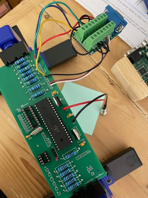
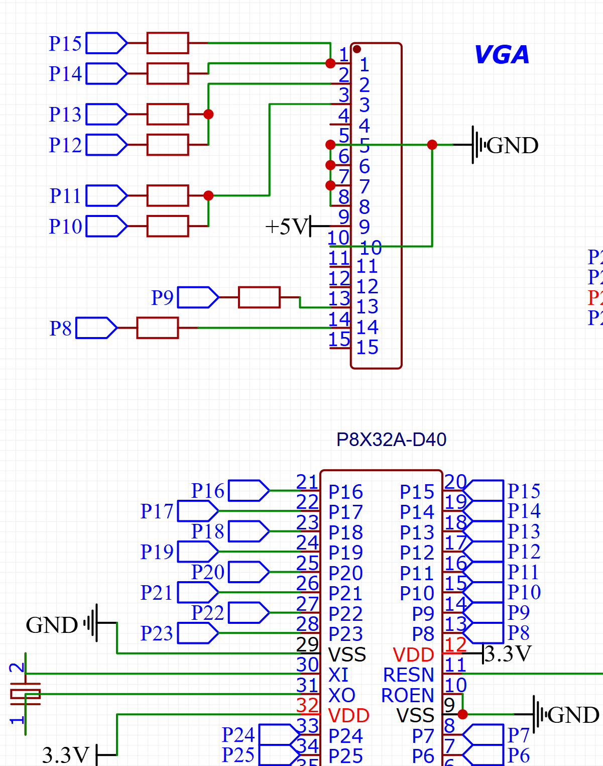
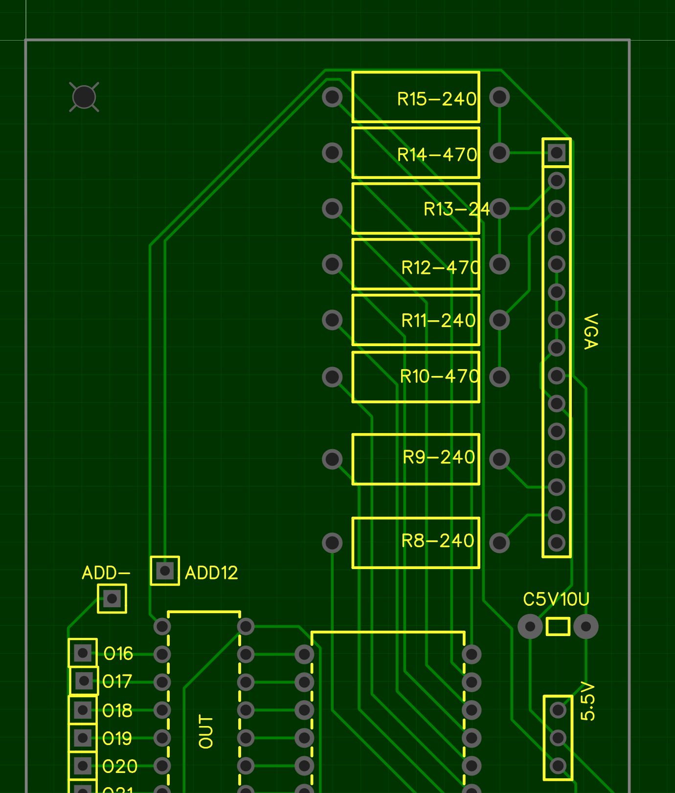
I'm building my own board based on the Propeller 1 and I can't get the VGA output to work. I think my schematic and PCB are correct. The code, cable, and monitor work, tested with a commercial Propeller Parallax board. I don't have many tools available (no oscilloscope, for example). How can I find the problem? I could test the outputs one by one with a multimeter, but what values should I expect? How do I test the sync?
The screen remains black.
**Thanks
**
Comments
Can you post the code you are testing with?
Schematic does look like might be correct…
Some monitors need the 5v but looks like you have it…
Output voltages to vga should be somewhere in between 3.3v and ground…. Unless screen is all white or all black…
You kind of need a scope or logic analyzer to investigate this electronically. A mere multimeter will do you no good, since it's the signal waveforms that matter. Though for this sort of thing, you don't need an expensive or modern one.
Schematic looks OK, but have you hooked up that breakout correctly?
For a monitor to turn on (off of standby or a "no signal" message), the important signals are Hsync and Vsync only.
If I don't connect the VGA cable, I get approximately 0.2V on hsync and vsync with a multimeter, and 0.1V on R, G, and B...
If I connect the cable (to the monitor), I get 0V everywhere:
pin 1: 0
2: 0
3: 0
4:
5: 0
6: 0
7: 0
8: 0
9: 5V
10: 0
11:
12: 5V
13: 0
14: 0
15: 5V
I connected pins 5, 6, 7, 8, and 10 together.
The 5V on pins 12 and 15 comes from the monitor because it's not connected to my board.
I also connected the GND of the cable to pins 5, 6, etc.
The microcontroller works fine; I get a HIGH signal from another pin, and it works.
Does your multimeter have a frequency mode?
It may be worth checking if the VGA breakout board is labelled correctly. These tests might be best done with all wires unhooked. The video pins should have about 75 Ohms to ground. The sync pins were 2200 Ohms to ground on a random monitor I just measured. And the I2C pins 12 and 15 had about 5v supplied by from the monitor, even though I didn't supply 5v to the monitor.
It should work with just one ground pin or just the connector shell. The video quality while doing that may not be great, but we're just trying to get the monitor to wake up right now.
This is my go to for P1 hookup, see attached. Some monitors require that you provide the 5V, as I recall.
Stupid! Stupid! Stupid! I'm stupid!
My code on my Pro card works because the VGA output pins are 16-23 and 8-15 on my card! Once I changed my code, it worked!!!
Thanks
Yeah that happens a lot.
Think a good idea to make comments in top level and driver code, near top of file, that user will probably need to adjust pin settings…
Just thinking that this particular case (where pairs of pins are connected with resistors) is one where the driver could actually test is the provided pin settings are good with vga cable connected…
I.e, detect if color pin is being pulled down by 75 ohm load…. Then maybe do some kind of warning if not…
Have to remember this for future driver work..