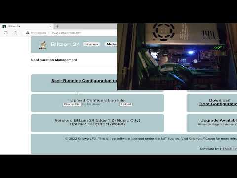
@evanh Yes, the P2 downloads the new image to itself from the Internet and then reboots. This is an older video, but this is what the process looks like.
@Rayman said:
A bit puzzling because not seeing anything in the source code that is pin# dependent...
I'm not at home at the moment but from memory it uses smartpin serial hardware in some parts and he's not bothered to calculate the clock pin offset pin when setting the smartpin mode.
I wanted to exchange the block level SD driver with something faster and smaller but that hasn't eventuated either. It's quite the tangle in there.
Oh, ouch, offset 5 between SD_MISO and SD_SCK. Not impossible but also not easy to fix the sources with that. That's Roger's 4-bit add-on pinout I presume?
I have not kept up with recent Spin developments, but I can't help wondering who thought mixing SPIN and PASM in this way was a good idea. Surely it makes maintaining, modifying or porting drivers like this far more complicated than it needs to be?
@RossH said:
I have not kept up with recent Spin developments, but I can't help wondering who thought mixing SPIN and PASM in this way was a good idea. Surely it makes maintaining, modifying or porting drivers like this far more complicated than it needs to be?
Stephen may have got a little excessive in misc and redundant routines using ORG/END but I will say, however, it's rather handy to have high-level locals (in registers) directly available to assembly. So I do like the inline Pasm2 ability in Spin2.
Defragmentation support, next-fit allocation, contiguous file creation, and Stale directory cluster fix.
### Added
- Next-fit allocator: Sequential writes produce more contiguous files, reducing fragmentation
- Defragmentation API (SD_INCLUDE_DEFRAG):
- fileFragments(): Count non-contiguous fragments in a file's cluster chain
- isFileContiguous(): Check if file clusters are stored contiguously
- createFileContiguous(): Create a file with pre-allocated contiguous cluster chain
- compactFile(): Relocate a fragmented file's clusters into a contiguous chain
- FSCK fragmentation reporting: Audit and FSCK summaries now report fragmented file count and total fragments
- New error codes: E_NO_CONTIGUOUS_SPACE, E_FILE_OPEN_FOR_COMPACT, E_VERIFY_FAILED
### Changed
- Volume label detection improved for cards with metadata before the label entry
- Regression suite expanded to 25 suites, 465 tests, all passing on hardware
### Fixed
- Fixed stale directory cluster when navigating or deleting in large subdirectories
@"Stephen Moraco" said:
- will add pin offset computation to the next update after v1.5.0.
MOSI can't do it but, for MISO it gets complicated if wanting to deal with offsets 4,5,6. By using an intermediate smartpin one can then stretch the two input pin numbers up to both a +3 and -3 at once to effect a total offset of up to 6.
Some of the complexity comes from the possibility of having to dodge pin numbers that are assigned another smartpin job. When the offset is 4 or 5 then choosing from more than one smartpin is an option.
And that still doesn't deal with the possibility of trampling on a smartpin that should have been allocated to another driver. But, since there is no smartpin allocation system, there's little that can be done other than don't accommodate beyond +-3 offsets.
The last part is keeping track of the extra pin number used for the MISO smartpin. It's a shuffle and looks messy.
@Rayman said:
Maybe not a problem for 4- bit setup because free to use non- 4 bit pins?
The sdsd.cc 4-bit SD mode driver doesn't use any serial smartpin modes. It only uses a single smartpin for SD clock gen. All CMD and DAT data is transferred with streamer ops.
Other more condensed pin groupings ok?
Yes, of course. It only matters when a smartpin requires a smartB input.
I'm trying to use the driver with a pretty old 1GB uSD card, it works with the default 350MHz system clock, but if I set it to 250MHz it always fails to mount, seems the minimum is around 290MHz.
@macca said:
I'm trying to use the driver with a pretty old 1GB uSD card, it works with the default 350MHz system clock, but if I set it to 250MHz it always fails to mount, seems the minimum is around 290MHz.
Is there something I can do to make it work ?
I have another card, more recent, 32GB, that works well at 250MHz.
The clock that works at is maybe partially telling... I found that some cards and the technologies they implement (the various ratings) can be sensitive to clock speeds. It would appear that the 350 is some multiple of some value that 250 is not in the same group. Once you find the multiple, then lower clock speeds of that multiple will likely work. Yes, I know this sounds odd. ;-) There is a frequency-sweep test that I used to try to gain insight into issues like this. Can you run it (make sure you have a copy of the contents before you mess around, just in case) to see where your device has issues with clock speed? @evanh's suggestion is also good, so we can tell which calls are failing. The mix of these findings should help us identify. If we find something we can make the code more robust against, I'll be glad to!
@"Stephen Moraco" said:
The clock that works at is maybe partially telling... I found that some cards and the technologies they implement (the various ratings) can be sensitive to clock speeds. It would appear that the 350 is some multiple of some value that 250 is not in the same group. Once you find the multiple, then lower clock speeds of that multiple will likely work. Yes, I know this sounds odd. ;-) There is a frequency-sweep test that I used to try to gain insight into issues like this. Can you run it (make sure you have a copy of the contents before you mess around, just in case) to see where your device has issues with clock speed? @evanh's suggestion is also good, so we can tell which calls are failing. The mix of these findings should help us identify. If we find something we can make the code more robust against, I'll be glad to!
Well... I managed to wipe the card anyway while testing various options so that's not a problem...
Running with the debug options enabled shows that it can do initCard without (apparent) problems but fails to readSector:
@macca, I led you to the wrong test. Let's try again.
Build and run diagnostic-tests/SD_frequency_characterize.spin2 against the 1GB card.
Post the full output (the test prints a results table at the end).
Build and run src/UTILS/SD_card_identify.spin2 — dumps CID + CSD + SCR + SD Status.
Post the full output for the failing 1GB card
This should give us some understanding. The results may lead to a custom test for you to run. This feels very much like we don't have enough margin for our data sampling for this card. Understanding which clock values fail in this new test tells us which clock division boundaries work for this card and which do not. That helps me dial in the sampling. We have tested a rich sample set of cards, and they all worked well with this current margin. You found a case where it's too close at some clock speeds. What I've seen in the past is that all clock speeds that result in the divider that works will work for this card. (Not that this is useful.) I'm hoping we'll be able to learn more and widen the operational range so your device can be added to the list of ones that work.
Also, it looks like the CARD IS LOCKED is the driver trying to interpret misaligned data. Which is why it doesn't make sense.
@"Stephen Moraco" said:
1. Build and run diagnostic-tests/SD_frequency_characterize.spin2 against the 1GB card.
2. Post the full output (the test prints a results table at the end).
That source seems to have a "typo", _CLKFREQ is set to 270MHz and I believe it should be set at 320MHz, with the default the initial mount fails.
Cog0 INIT $0000_0000 $0000_0000 load
Cog0 INIT $0000_0F64 $0000_9408 jump
Cog0
Cog0 ============================================================
Cog0 SD Frequency Sweep Test (V2 Driver)
Cog0 ============================================================
Cog0 Purpose: Find sysclk frequencies where streamer timing fails
Cog0 Test: writeSectorsRaw(8) + readSectorsRaw(8) + verify
Cog0
Cog0 Initial mount at 320 MHz...
Cog1 INIT $0000_0F64 $0000_1EC2 jump
Cog0 ERROR: Initial mount failed!
Cog0
Cog0 END_SESSION
If I set the _CLKFREQ to 320MHz seems it stucks at clkset inside changeFrequency...
' STREAMER BULK TRANSFER: 512 bytes from MISO to hub via DMA
ORG
DIRL _sck ' Reset SCK: counter stops, output LOW, Y=0
DRVL _sck ' Re-enable: DIR=1 restarts base period counter fresh
SETXFRQ xfrq ' Set streamer NCO rate
WRFAST #0, p_buf ' Setup WRFAST to hub buffer
WYPIN clk_count, _sck ' Start clock transitions
WAITX align_delay ' Wait one half-period to align with first rising edge
XINIT stream_mode, init_phase ' Start streamer with phase offset
WAITXFI ' Wait for streamer to complete
END
The WRFAST, in particular, needs to be ahead of the rising DIR smartpin control. This is because WRFAST can be erratic in how many sysclock ticks it takes to execute. And consistency of ticks is critical between the rising DIR and XINIT to retain clock-data phase alignment.
Secondly, a change in clock divider value, when small, will upset the timing when high number of ticks exist between rising DIR and WYPIN. This is due to the way the smartpin cycles internally - Cycling begins as soon as DIR rises. A new pulse series, from a WYPIN, begins only on a whole cycle boundary, independent of WYPIN execution time - Which is always 2 ticks. Consistency is attained by placing the WYPIN immediately following the rising DIR.
Here's my recommendation:
' STREAMER BULK TRANSFER: 512 bytes from MISO to hub via DMA
ORG
WRFAST #0, p_buf ' Setup WRFAST to hub buffer
SETXFRQ xfrq ' Set streamer NCO rate
FLTL _sck ' Reset SCK: counter stops, output LOW, Y=0
DIRH _sck ' Re-enable: DIR=1 restarts base period counter fresh
WYPIN clk_count, _sck ' Start clock transitions
WAITX align_delay ' Wait one half-period to align with first rising edge
XINIT stream_mode, init_phase ' Start streamer with phase offset
WAITXFI ' Wait for streamer to complete
END
Lastly, there is the internal long route staging registers inside the Prop2 I/O paths, and other latencies in the outer pad-ring that adds further ticks at higher sysclock frequencies. For pin reads, these can add up to quite a number of ticks from the outputting of an SD clock edge to the streamer sampling of the SD response. Having extra compensation is a good idea. Your default align_delay calculation of half SD clock cycle is probably borderline, but I'll leave this detail for later.
@evanh said:
The WRFAST, in particular, needs to be ahead of the rising DIR smartpin control. This is because WRFAST can be erratic in how many sysclock ticks it takes to execute. And consistency of ticks is critical between the rising DIR and XINIT to retain clock-data phase alignment.
WRFAST only takes extra cycles if there's still data buffered from a previous write. (Unlike RDFAST). Though moving it to the top is probably a good idea, anyways.
True, there is RDFAST in another part ... but that needs a far more in-depth discussion - After Macca get results on resolving the first SD block read.
PS: Stephen has opted for a variable divider - to better fit the SD standard. Compared to Roger's work with PSRAM drivers, this has opened up a can of worms that needs dealt with. Again, I had wanted to just plug-in the already proven SD drivers from Flexspin efforts.
@evanh I'm studying what you've provided. Thank you for providing this. I'm also studying the configuration math for the read/write streamer pipelines. I believe we have a fixed value in there instead of a calculated one, which then puts us in the marginal behavior areas of the signal. More soon.


Comments
So you're also storing the programs using the Prop2? It had sounded like you were doing that from the desktop after compiling.
@evanh Yes, the P2 downloads the new image to itself from the Internet and then reboots. This is an older video, but this is what the process looks like.
A tad late.
Tried this out and works great for usual P2 uSD pins. But, doesn't seem to work on other pins...
Tried this:
    SD_BASE = 0
    SD_SCK  = SD_BASE + 5              ' - Serial Clock
    SD_CS   = SD_BASE + 3              ' - Chip Select
    SD_MOSI = SD_BASE + 4              '  - Master Out, Slave In
    SD_MISO = SD_BASE + 0              '  - Master In, Slave Out
with no luck...
A bit puzzling because not seeing anything in the source code that is pin# dependent...
I'm not at home at the moment but from memory it uses smartpin serial hardware in some parts and he's not bothered to calculate the clock pin offset pin when setting the smartpin mode.
I wanted to exchange the block level SD driver with something faster and smaller but that hasn't eventuated either. It's quite the tangle in there.
Clock pin offset, guess that would do it…
Oh, ouch, offset 5 between SD_MISO and SD_SCK. Not impossible but also not easy to fix the sources with that. That's Roger's 4-bit add-on pinout I presume?
I have not kept up with recent Spin developments, but I can't help wondering who thought mixing SPIN and PASM in this way was a good idea. Surely it makes maintaining, modifying or porting drivers like this far more complicated than it needs to be?
@evanh yes, that is one of them that didn’t work….
Stephen may have got a little excessive in misc and redundant routines using ORG/END but I will say, however, it's rather handy to have high-level locals (in registers) directly available to assembly. So I do like the inline Pasm2 ability in Spin2.
Inline assembly is awesome and using for uSD drivers makes a lot of sense... You get close to the performance of pure assembly with a lot more ease...
@evanh @Rayman - will add pin offset computation to the next update after v1.5.0. Good catch.
NEWS
I released v1.5.0 a couple of days ago.
Here's what's new/fixed:
Visit the P2 microSD FAT32 Filesystem repository for full documentation, including a driver tutorial, theory of operations, and card catalog.
The release package can be downloaded from the Releases page. Download the sd-card-driver-{version}.zip
file.
If you find issues, please file them at the Issues page.
What's next? Quickly address any reported issues. Likely conditional compile for LFN support.
Enjoy!
Stephen
MOSI can't do it but, for MISO it gets complicated if wanting to deal with offsets 4,5,6. By using an intermediate smartpin one can then stretch the two input pin numbers up to both a +3 and -3 at once to effect a total offset of up to 6.
Some of the complexity comes from the possibility of having to dodge pin numbers that are assigned another smartpin job. When the offset is 4 or 5 then choosing from more than one smartpin is an option.
And that still doesn't deal with the possibility of trampling on a smartpin that should have been allocated to another driver. But, since there is no smartpin allocation system, there's little that can be done other than don't accommodate beyond +-3 offsets.
The last part is keeping track of the extra pin number used for the MISO smartpin. It's a shuffle and looks messy.
Maybe not a problem for 4- bit setup because free to use non- 4 bit pins?
Other more condensed pin groupings ok?
The sdsd.cc 4-bit SD mode driver doesn't use any serial smartpin modes. It only uses a single smartpin for SD clock gen. All CMD and DAT data is transferred with streamer ops.
Yes, of course. It only matters when a smartpin requires a smartB input.
So another option for Stephen is to stop using the serial smartpins and switch to using the streamer for everything.
@evanh meant that for the 4bit setup in 1bit mode there are free pins that can be used…. Maybe that helps…
Yes, fine for that add-on. And it's unlikely there would ever be a design that interleaves pins between uses but you never know for sure.
There are SPI display modules with built in uSD, that may or may not be another case…
I'm trying to use the driver with a pretty old 1GB uSD card, it works with the default 350MHz system clock, but if I set it to 250MHz it always fails to mount, seems the minimum is around 290MHz.
This is the output of SD_FAT32_audit at 250 MHz
Is there something I can do to make it work ?
I have another card, more recent, 32GB, that works well at 250MHz.
Add a debug mask to get some info card handling. eg: At line 114 change
DEBUG_MASK = 0toDEBUG_MASK = (1 << CH_INIT) | (1 << CH_MOUNT)The clock that works at is maybe partially telling... I found that some cards and the technologies they implement (the various ratings) can be sensitive to clock speeds. It would appear that the 350 is some multiple of some value that 250 is not in the same group. Once you find the multiple, then lower clock speeds of that multiple will likely work. Yes, I know this sounds odd. ;-) There is a frequency-sweep test that I used to try to gain insight into issues like this. Can you run it (make sure you have a copy of the contents before you mess around, just in case) to see where your device has issues with clock speed? @evanh's suggestion is also good, so we can tell which calls are failing. The mix of these findings should help us identify. If we find something we can make the code more robust against, I'll be glad to!
Well... I managed to wipe the card anyway while testing various options so that's not a problem...
Running with the debug options enabled shows that it can do initCard without (apparent) problems but fails to readSector:
If I comment the "Card identification and speed selection" step, it goes a little further:
Don't know why it reports CARD_IS_LOCKED.
The frequency-sweep test shows no errors:
Seems the initial SPI settings are working to some extent, but then fails for some other reasons.
@macca, I led you to the wrong test. Let's try again.
diagnostic-tests/SD_frequency_characterize.spin2against the 1GB card.Post the full output (the test prints a results table at the end).
Build and run
src/UTILS/SD_card_identify.spin2— dumps CID + CSD + SCR + SD Status.This should give us some understanding. The results may lead to a custom test for you to run. This feels very much like we don't have enough margin for our data sampling for this card. Understanding which clock values fail in this new test tells us which clock division boundaries work for this card and which do not. That helps me dial in the sampling. We have tested a rich sample set of cards, and they all worked well with this current margin. You found a case where it's too close at some clock speeds. What I've seen in the past is that all clock speeds that result in the divider that works will work for this card. (Not that this is useful.) I'm hoping we'll be able to learn more and widen the operational range so your device can be added to the list of ones that work.
Also, it looks like the CARD IS LOCKED is the driver trying to interpret misaligned data. Which is why it doesn't make sense.
That source seems to have a "typo", _CLKFREQ is set to 270MHz and I believe it should be set at 320MHz, with the default the initial mount fails.
If I set the _CLKFREQ to 320MHz seems it stucks at clkset inside changeFrequency...
I tried with both my Spin Tools and pnut_ts just to be sure it isn't something in the compiler.
Stephen, your streamer code is a tad unstable:
      ' STREAMER BULK TRANSFER: 512 bytes from MISO to hub via DMA
      ORG
              DIRL      _sck                            ' Reset SCK: counter stops, output LOW, Y=0
              DRVL      _sck                            ' Re-enable: DIR=1 restarts base period counter fresh
              SETXFRQ   xfrq                            ' Set streamer NCO rate
              WRFAST    #0, p_buf                       ' Setup WRFAST to hub buffer
              WYPIN     clk_count, _sck                 ' Start clock transitions
              WAITX     align_delay                     ' Wait one half-period to align with first rising edge
              XINIT     stream_mode, init_phase         ' Start streamer with phase offset
              WAITXFI                                   ' Wait for streamer to complete
      END
The WRFAST, in particular, needs to be ahead of the rising DIR smartpin control. This is because WRFAST can be erratic in how many sysclock ticks it takes to execute. And consistency of ticks is critical between the rising DIR and XINIT to retain clock-data phase alignment.
Secondly, a change in clock divider value, when small, will upset the timing when high number of ticks exist between rising DIR and WYPIN. This is due to the way the smartpin cycles internally - Cycling begins as soon as DIR rises. A new pulse series, from a WYPIN, begins only on a whole cycle boundary, independent of WYPIN execution time - Which is always 2 ticks. Consistency is attained by placing the WYPIN immediately following the rising DIR.
Here's my recommendation:
      ' STREAMER BULK TRANSFER: 512 bytes from MISO to hub via DMA
      ORG
              WRFAST    #0, p_buf                       ' Setup WRFAST to hub buffer
              SETXFRQ   xfrq                            ' Set streamer NCO rate
              FLTL      _sck                            ' Reset SCK: counter stops, output LOW, Y=0
              DIRH      _sck                            ' Re-enable: DIR=1 restarts base period counter fresh
              WYPIN     clk_count, _sck                 ' Start clock transitions
              WAITX     align_delay                     ' Wait one half-period to align with first rising edge
              XINIT     stream_mode, init_phase         ' Start streamer with phase offset
              WAITXFI                                   ' Wait for streamer to complete
      END
Lastly, there is the internal long route staging registers inside the Prop2 I/O paths, and other latencies in the outer pad-ring that adds further ticks at higher sysclock frequencies. For pin reads, these can add up to quite a number of ticks from the outputting of an SD clock edge to the streamer sampling of the SD response. Having extra compensation is a good idea. Your default
align_delaycalculation of half SD clock cycle is probably borderline, but I'll leave this detail for later.WRFAST only takes extra cycles if there's still data buffered from a previous write. (Unlike RDFAST). Though moving it to the top is probably a good idea, anyways.
True, there is RDFAST in another part ... but that needs a far more in-depth discussion - After Macca get results on resolving the first SD block read.
PS: Stephen has opted for a variable divider - to better fit the SD standard. Compared to Roger's work with PSRAM drivers, this has opened up a can of worms that needs dealt with. Again, I had wanted to just plug-in the already proven SD drivers from Flexspin efforts.
@evanh I'm studying what you've provided. Thank you for providing this. I'm also studying the configuration math for the read/write streamer pipelines. I believe we have a fixed value in there instead of a calculated one, which then puts us in the marginal behavior areas of the signal. More soon.