

P2 Smart Pin Pulse Mode Silicon Bug Report
 Christof Eb.
Posts: 1,598
Christof Eb.
Posts: 1,598
Goal: Output a group of 16 pulses to drive a step driver module with the Smart Pin Pulse Mode and then output the next group. With only a very small gap due to the time needed for new setup.
Problem: Although the smartpin mode is completely stopped after every group (see code) the pulse stream is not realigned to the setting intervals. (Which are timed with waitct1)
To show the bug in this case setting interval is 17 cycles. So you would always expect a gap of slightly more than one output cycle. Instead the start of the next group shifts in relation to the setting and sometimes the gap is there and sometimes not.
Blue is port 48 to show the relation.
PRIMI(startPulses) { // ( x y pin -- ) starts smart mode pulses
        _pinh(48);
        int pin= TOS; _drop();
        int y = TOS; _drop();
        int x= TOS; _drop();
        _pinclear(pin);
        _pinstart(pin,P_OE | P_PULSE, x, y);
        _pinl(48);
}
compiles to:
04b50                 | __startPulses
04b50     59 60 64 FD |     drvh    #48
04b54     E0 D7 02 F6 |     mov arg01, pr0
04b58     04 C8 87 F1 |     sub pr4, #4
04b5c     E4 C1 03 FB |     rdlong  pr0, pr4
04b60     E0 DD 02 F6 |     mov arg04, pr0
04b64     04 C8 87 F1 |     sub pr4, #4
04b68     E4 C1 03 FB |     rdlong  pr0, pr4
04b6c     E0 DB 02 F6 |     mov arg03, pr0
04b70     04 C8 87 F1 |     sub pr4, #4
04b74     E4 C1 03 FB |     rdlong  pr0, pr4
04b78     50 D6 62 FD |     fltl    arg01
04b7c     6B 01 08 FC |     wrpin   #0, arg01
04b80     40 D6 62 FD |     dirl    arg01
04b84     6B 91 08 FC |     wrpin   #72, arg01
04b88     6B DB 12 FC |     wxpin   arg03, arg01
04b8c     6B DD 22 FC |     wypin   arg04, arg01
04b90     41 D6 62 FD |     dirh    arg01
04b94     58 60 64 FD |     drvl    #48
04b98                 | __startPulses_ret
04b98     2D 00 64 FD |     ret
(If you are using the IN bit of the smart pin to restart the group you always loose one output cycle.)
Neither wrpin #0 nor dirl does really stop the smart pin.
Please verify and include this to the known Bugs. It has cost me some hours.
Christof
Comments
The smartpin output is toggling even after a dirl?
It does take a couple cycles for dirl to take effect right, or doesn’t it?
Is the pin output changing state even after that?
I use pulse to output the step pulse for sw generated stepper pulses...
initialize it..
then output a pulse with a unit width of 1uSec. at my 200Mhz clock
I do the pinstart() once, then just do a wypin() whenever I need to output a pulse.
From the p2 silicon doc
This mode overrides OUT to control the pin output state.
X.[15..0] establishes a base period in clock cycles which forms the empirical high-time and low-time units.
X.[31..16] establishes a value to which the base period counter will be compared to on each clock cycle, as it counts from X.[15..0] down to 1, before starting over at X.[15..0] if decremented Y > 0. On each clock, if the base period counter > X.[31..16] and Y > 0, the output will be high (else low).
Whenever Y.[31..0] is written with a non-zero value, the pin will begin outputting a high pulse or cycles, starting at the next base period. After each pulse, Y is decremented by one, until it reaches zero, at which the output will remain low.
Some examples:
If X.[31..16] is set to 0, the output will be high for the duration of Y > 0.
If X.[15..0] is set to 3 and X.[31..16] is set to 2, the output will be 0-0-1 (repeat) for the duration of Y > 0.
IN will be raised and the pin will revert to low output when the pulse or cycles complete, meaning Y has been decremented to zero.
During reset (DIR=0), IN is low, the output is low, and Y is set to zero.
%00101 = transition output
This mode overrides OUT to control the pin output state.
X.[15..0] establishes a base period in clock cycles which forms the empirical high-time and low-time units. The base-period counter begins decrementing and periodically reloading as soon as the smart pin is out of reset. All transition outputs will be synchronized to this free-running base period.
Whenever Y.[31..0] is written with a non-zero value, the pin will begin toggling for Y transitions at each base period, starting at the next base period.
IN will be raised when the transitions complete, with the pin remaining in its current output state.
During reset (DIR=0), IN is low, the output is low, and Y is set to zero.
I think the problem is that in pulse mode the internal counter for the base period (X[15..0]) continues to run even if the output is stopped. When the next values for duty cycle (X31..16]) and number of cycles (Y) are re-loaded the base period counter is not synchronized but instead starts with a random phase shift inherited from the last register update.
I don't know if there is a reset sequence that can work around this. IIRC, DIR=0 is not enough. Try DIR=0 followed by a write of X[15..0]=1 or something like that to reset the counter.
X register has two parts. Nominally X[31:16] = X[15:0]>>1
DIR low holds the smartpin mode (P_PULSE) in reset. Clears Y as well. DIR controls the starting of the cycle.
Yes, setting X = 1 then back to desired value will also resync cycle but Y would need to be zero already so is not an advantage over DIR.
Have you tried just resetting with DIR instead of rewriting all the registers? IME that works to realign the timing.
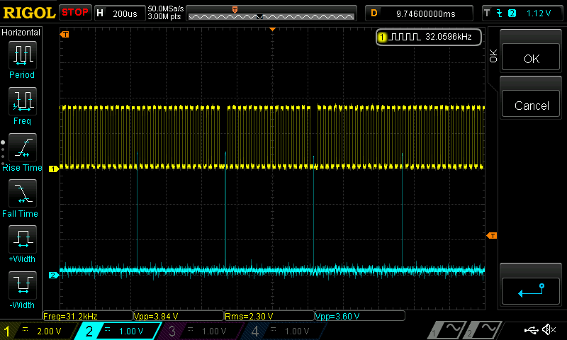
When I write wypin(), I always get a pulse width output of increments of 200 clocks... not like a random number between 1 and 200...
Like when wYpin gets written to 1, output goes high, the down counter starts at 200 and counts down to 0 before out goes low and y decrements...
So, this works perfectly in this case... Low width is actually period width...
Oh yes, during these hours I have tried this among everything else I could think of.
If you just DIRL then the pin becomes zero immediately. If you then DIRH it goes back to the state, which is given by the old (!) smartpin settings at this time. With the old timing, even if you have changed them. Only when the next cycle is due, the new settings will take effect.
This is why I call it a bug.
The Transition Mode has the same behaviour. But you can use IN, because this will signal directly after the last transition. So for two Transitions you have High, Pause, Low, (IN), Pause and you can wait for IN and setup newly during the second pause.
Yes, you are right, the pulse mode might not behave as you expected. But I think it was never meant for things like controlling stepper motors. You simply don't have the full control of the phase and you definitely have too little resolution for the timing to generate a seamless series of pulses without gaps in between. Pulse mode only supports frequencies that are an integer fraction of the system clock. So you either need a variable pulse-group time or you'll have rounding errors at the transitions.
NCO mode is much better for this so why not use it?
That is definitely wrong for X.
What you are likely dealing with is that cycling starts on rising DIR. A new Y value only takes effects on a whole cycle boundary. So any Y value loaded immediately after DIR high will begin after the first cycle has passed. And of course Y can't be loaded before DIR high.
You probably want to go finer X values, or follow ManAtWork's path with NCO modes instead.
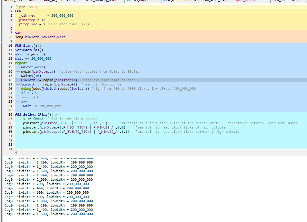
I am using the P-PULSE smartpin setting to output a proper pulse width for a stepper "step" signal.
Turns out I was having a similar problem.
I had the base period counter set to 200 with a 200Mhz clock making the base period 1uSec.
Then with a WYPIN(pin,uSeconds) I could out output a perfect pulse width. But turns out there can be a lag between the WYPIN write and the pulse output start...
It only starts when the base count gets down to zero.
So, I did what Evan said, go with a finer base period. I set base period to 1, and have to write a value of 200 in WYPIN to get a uSec...
My program has a waitcnt loop at 200_000_020 clocks, so after each loop the residual in the base period is 20 counts less, and the lag between the WYPIN write and the pulse output is 20 clocks shorter...
The first 20 loops use the finer resolution on base period, the second 20 use a base period of 200... and in the second 20 you can see the lag time get shorter after each loop...