

ez_spi question
 kwagner
Posts: 50
kwagner
Posts: 50
I'm trying to use the ez_spi driver in a program and getting some confusing results. Trying to get to ground level in troubleshooting, I'm testing the following:repeat i from 0 to 9
spi.shiftout(spi.LSBFIRST,i,8)
So the values I should get on my logic analyzer are 0,1,2,3,etc.
Instead, it appears the first bit is at the end, but everything else is in alignment.
So my values (bitwise) on the line look like:
00000000
00000001
10000000
10000001
01000000
01000001
11000000
11000001
etc
If I instead switch to MSBFIRST, it looks like I have a padded 0:
00000000
00000010
00000100
00000110
00001000
00001010
00001100
00001110
etc
The results are the same even if I put it to 32 bits (just more empty bits in between). I'm using flexprop for compilation so I'm not sure if there's a bug in that or I'm doing something wrong. I grabbed the ez_spi driver from the obex, but it also was last updated in 2020, so not sure if something changed between then and now as far as smart pins or hardware goes?
Any help would be appreciated.
Comments
You might try messing with the SPI clock frequency... Things can go wrong if too fast..
Also, the SPI mode should match the analyzer..
I'm using JM_SPI.spin2 and it seems to work. Although defs for sdo and sdi seem backwards to me..
My frequency is 1MHz, I tried lowering it to 100kHz with the same results.

Here's a pic of what it looks like on the analyzer for LSBFIRST (ignore the two noise bits from me breaking out the signals)
FTR... I don't use jm_spi.spin2 anymore -- it's a very old program and was trying to do everything for every situation, which usually results in everybody being unhappy.
I've also dumped the politically-correct nomenclature in my code and gone back to MOSI and MISO which are nom-ambiguous.
How did you start the SPI object? In the future, I suggest you archive and upload troublesome code for others to run.
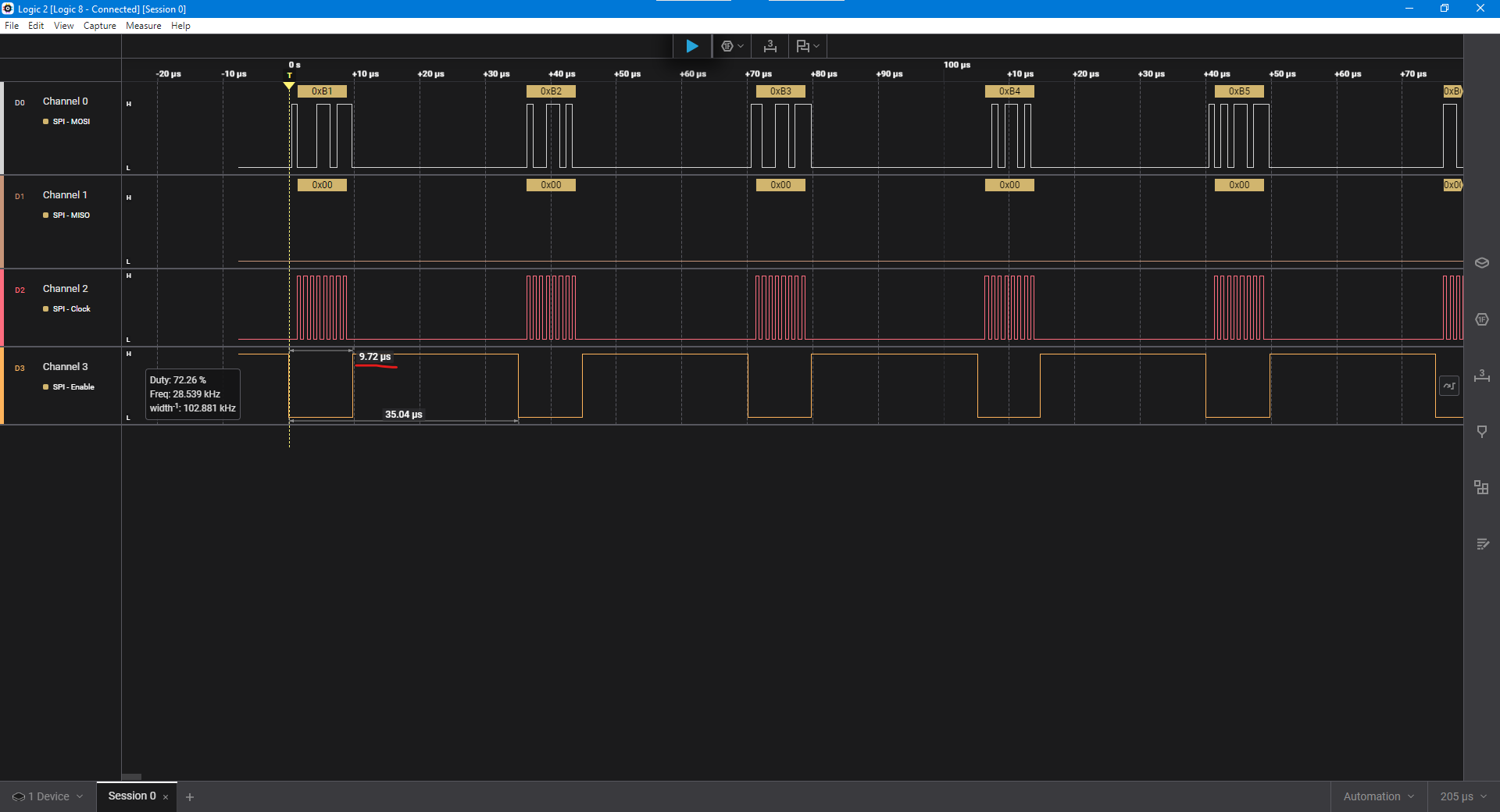
@kwagner There were a few things I didn't like about jm_ez_spi.spin2 so I saved it with a slightly different name, jm_ez-spi.spin2 (note dash replaces underscore) to prevent breaking other programs and I updated to my current liking. I did a quick demo with shiftout() and it works fine. And while I feel no responsibility to make my code work with FlexProp, I did run this demo through it and it works fine as far as I can tell. Below you see images from my LA using Spin Tools (interpreted) and FlexProp (compiled). Since the SPI clock is running a fixed rate via a smart pin the place to see the difference is in the time the CS pin spends low.
shiftout() demo in Spin Tools
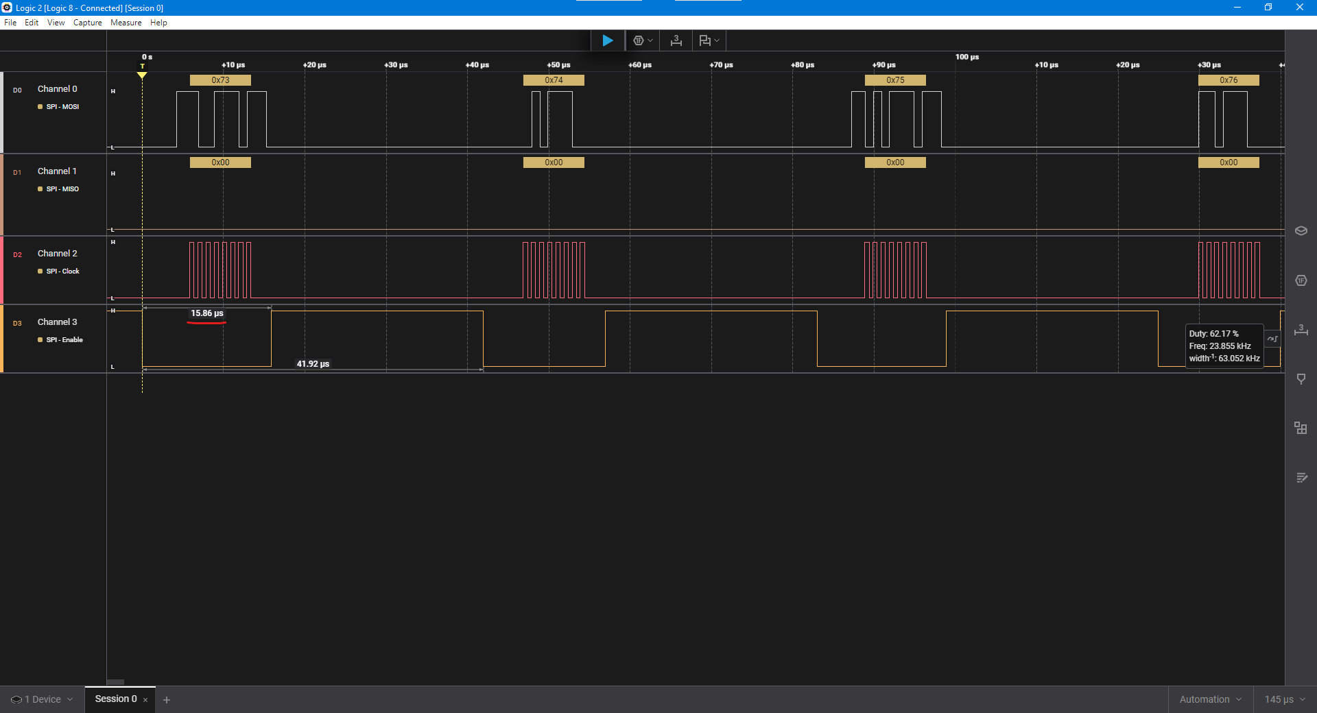
shiftout() demo in FlexProp
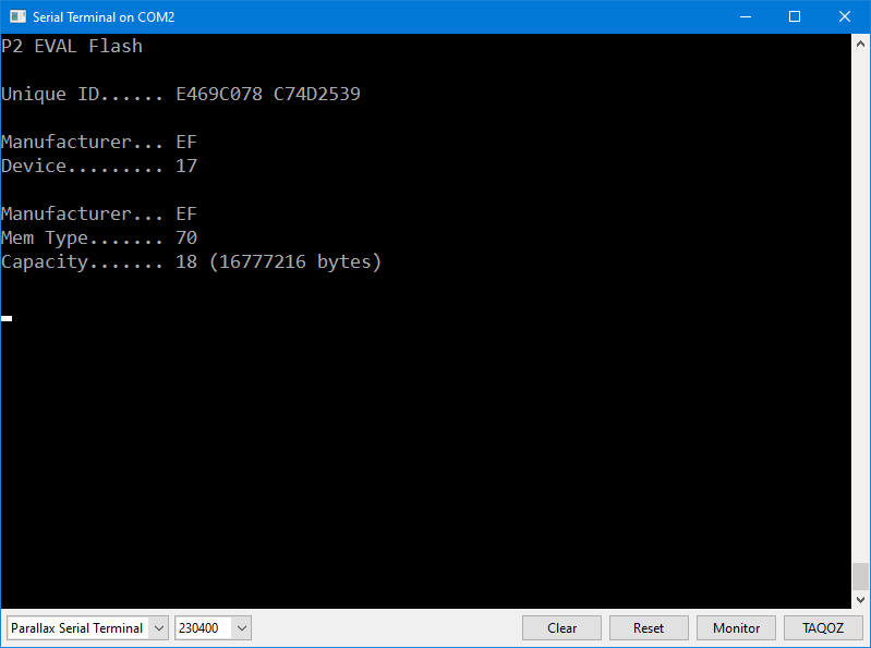
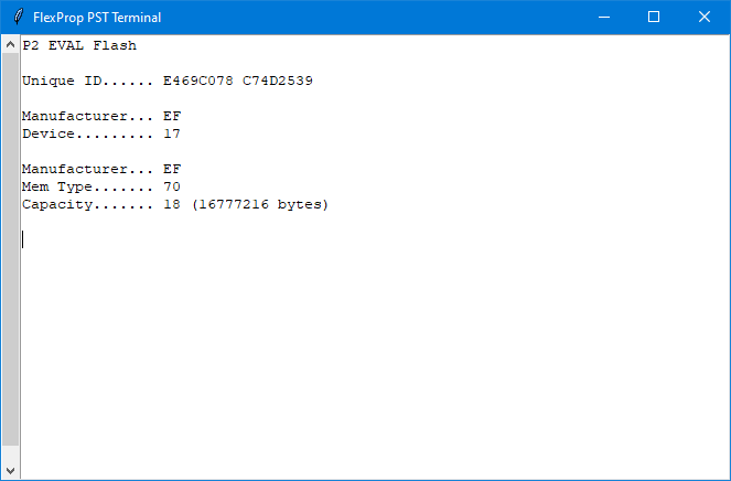
I also tested the object using the P2 flash so that shiftout() and shiftin() could be tested. It works fine Spin Tools and FlexProp.
Flash demo in Spin Tools
Flash demo in FlexProp
NOTE: See post #9 for latest JM code.
Is there any chance you're running an inexpensive logic analyzer (I got one from Amazon for $13) and using PulseView? Based on your screen cap, I gave my cheap LA a try and it acted like what you're seeing. Clock and CS signals are fine, but MOSI is garbled. As the cheap LA will look like an old Saleae device in their software, I tried that, too, and got the same garbled results. I can't explain it. I even tried moving the MOSI pin away from the others and still had a problem. Unfortunately, PulseView doesn't work with my Logic-8 Pro so i couldn't check that.
You can see that it's fine with the 1MHz clock signal, but MOSI is broken. I think it has something to do with the way the device samples the bus. I have an idea that I will try after lunch.
After experimenting this afternoon I am convinced that the problem is your logic analyzer. Given the way smart pins operate I thought I'd try an inline PASM approach; it seems to work, probably because the inline PASM code has more breathing room between the MOSI output and the rising edge SCLK signal -- this seems to make a difference with the low-cost LA using PulseView. In this capture I'm running SPI at 1MHz.
Please give this new object, jm_ip-spi.spin2, a try in your project. I hope this helps.
As before, I tested it with the flash interface. It works, too.
NOTE: See post #9 for latest JM code.
That should fix it. The code @kwagner was using didn’t seem to set mosi before the rising edge of sck….
Seems in spi mode 0 the data is sampled on the rising edge of sck. The data @kwagner showed seems to look bad….
But maybe the logic analyzer was doing something weird. A very slow spi clock maybe shows something different?
It seems to, even when compiled by FlexProp. I'm really confused about the logic analyzer: When running the smart pin SPI it sees the 1MHz SPI clock with no problem but the MOSI data is a mess. I though that the LA is doing 8-bit parallel samples at the specified rate and the protocol analyzer sorts things out after, but the MOSI capture is fouled. I even tried reversing the order of the pins but that made no difference.
In the end, I have verified my smart pin mode 0 SPI works, and now there's a cleaner inline PASM version that also works and will display properly with a low-cost LA and PulseView software.
I've spent a lot of time looking at this because I have projects and other objects that use SPI and I really wanted to ensure there are no problems with my code (which affects work and friends). I don't think there are -- that said, I still made some clean-ups and small improvements to my simple SPI objects. I believe the problems that @kwagner reported has to do with his/her logic analyzer.
While looking over some of my objects I remembered that some forum members asked me to make my P2 Flash object run in SPI mode 2 (inverted clock) given the cross-connections between the flash and the uSD on the Eval and Edge PCBs. On a hunch based on what I'd seen with the bit-bang code, I tried Mode 2 with the Smart Pin SPI using the low-cost logic analyzer (LCLA) and it displayed data properly! Here it is:
Note that the SCLK line is inverted for Mode 2 SPI. You need to tell the protocol analyzer about this:
The setup() method has a new parameter for CPOL (clock polarity):
Now... if you really want to use Mode 0 (CPOL=0, SCLK is low when idle) then use the object called jm_ip-spi.spin2. This object uses inline PASM to bit-bang the SPI signals and sets the MOSI pin 1/2 cycle ahead of the first SCLK edge which seems to be okay with the LCLA.
Remember to set CPOL back to 0 in the SPI protocol analyzer settings.
KWagner: You may want to use this so you can see what's under-the-hood with SPI, and even experiment with modifying how the object works (if you do, take my name off of any modified code before you share with others).
I'm calling a wrap on this code check/update and feel secure my simple SPI code is in good shape, and that KWagner has the tools to continue experimenting.