P2BrightBall: P2+BW Camera as a Position Sensor, Balancing a White Marble
 Christof Eb.
Posts: 1,534
Christof Eb.
Posts: 1,534
This is some fun experiment and work in progress. Goal is to control the path of the marble.
Hardware consists of a P2 Kiss Bord with attached BW Camera as 2-dimensional position sensor to detect a white marble on a black background. The marble runs on a plain, which can be tilted in two directions using 2 standard 180° RC servos. Mechanics is a labyrinth game.
Diameter of this glass marble is 13,77mm, weight: 3.35 grams
The usable size of the plain is 264mmx223mm
Vertical distance of the camera from plain: 390mm
Camera: https://forums.parallax.com/discussion/178031/connecting-a-bw-320x320-pixels-camera-arducam-hm01b0-to-parallax-propeller-p2-via-4-lines#latest but using resolution 160x160 Pixels
There is a 1W LED lamp close to the camera to avoid asymmetrical shadows.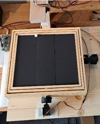
There are some camera projects in the net to be found mostly using some sort of AI with complicated and slow picture analysis. In this case here we can "design the problem", so we are using a very dark background and a very bright marble. Also we know for example the size of the marble. The automatic exposure of this camera works well, so we can use an absolute threshold.
The idea is then to have a simple way of finding the marble in the picture to get a high update rate for the position. For sake of speed also the resolution of the picture is reduced.
This is, how the camera sees the marble in the top left corner: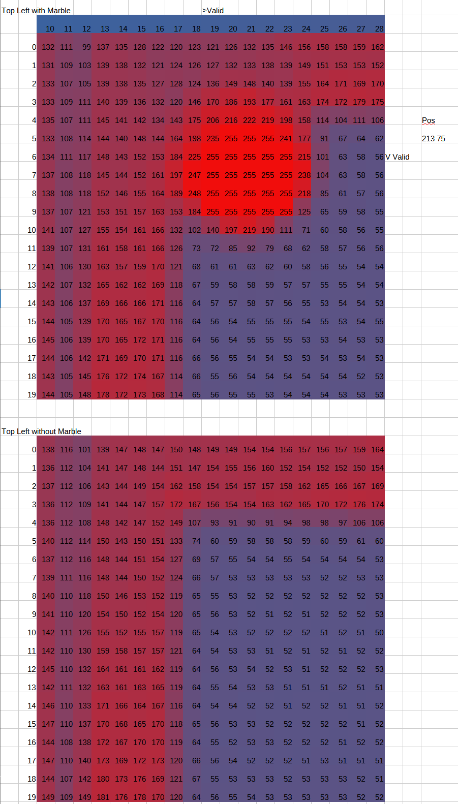
The wooden frame is rather bright too, so this is cut away.
The very simple method to get the position is right now to consider every pixel with brightness > 210 as part of the marble.
pub calcBallPos() | index, line , val, n, nc, nl '###########################################
    n, nc, nl:=0 , 0 , 0

    repeat line from LMIN to LMAX
        repeat index from CMIN to CMAX
            val:= picBuf.byte[line*(164) + index+4] ' 4 border pixels
            if(val>BBRIGHT)
               'term.tx(grey95.byte[95 - 95*val/255])
               n+=1
               nc+=index
               nl+=line
    if(n>0)
      colPos:= 10*nc/n
      linePos:= 10*nl/n
The idea is to try a PID-controller or rather two of them for the 2 directions. At the moment I am trying to learn about the system. There is an interesting Autotune Method to set the PID parameters, which gets information about the system via a Relay test: https://pages.mtu.edu/~tbco/cm416/Atune.html
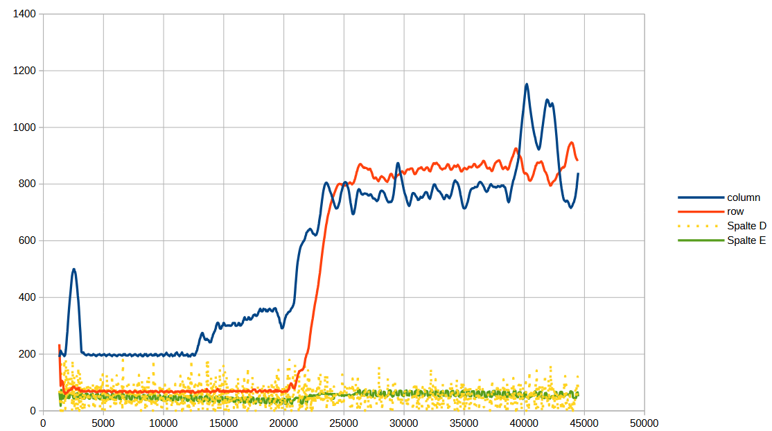
So with an angle amplitude of 9 degrees at the servo (at the plain it is less), we get the following behaviour: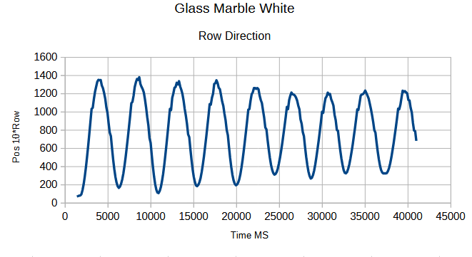
Cycle time for this is about 4600ms and resulting amplitude is about 89 rows.
....
Cheers Christof
Comments
Looks like fun!
Wonder is a steel ball would be easier to control…
Yes, more inertia would be easier, if it has the same diameter.
My steel and brass balls only have D= 11mm. So they are only slightly more inertia. The camera can detect both.
Big problem is, that the ball hangs on minimal uneveness of the surface. The original game is very difficult for myself.
The PID controllers are working now and the Relay method has given good start values for the parameters. Now the system has to be tuned....
Some progress:
Instead of switching the camera stream on and off via i2c, which gave a frame rate of 7.5/sec now the camera sends pictures continuously, which gives a frame rate of 23/sec and same update rate for the position. That helps a lot.
Using the FlexSpin compiler only one COG is used at the moment. Grab frame, calculations of position and PID all fit into each 43 ms cycle.
PID controllers are modified:
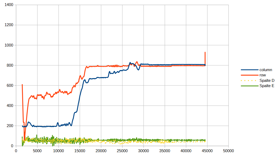
Picture shows positions over time.
Line direction works better. There is more mechanical waviness like valleys in column direction. Unsticking column direction also gets ball to move along line direction.
I now did some research. There are some projects, where people have used a resistive touch panel for the position with a rather heavy ball. The plain is very smooth and even and they are happy, if the ball stays on the plain. Well, I can say, that I have achieved this too. For this a normal PID controller is sufficient.
There also are papers which deal with friction. One possibility seems to be to reset the integral when the ball is moving again. Another possibility seems to be to work with pulses and to vary their height or length. In my case the speed of the servo motors play a role here too now, that I have a faster frame rate: The peak of a pulse cannot be reached, if it is too short.
Interesting, these servo motors also work with faster pulse period. 10ms is better than 20ms. 8ms works too but gives a strange noise.
I am now doing the frame grabbing and calculation of position in a separate cog.
This is a 2nd order integral problem. With the RC servos you control tilt angle which directly corresponds to the acceleration of the marble. You want to control position which is the 2nd integral of acceleration. I think, a single PID is very difficult to tune for this application. You should try two nested PID loops where the inner loop controls the speed of the marble.
Hm, thank you for the hint, yes, perhaps I should try something like this. Perhaps I can use a positive or negative or zero constant speed for the outer loop and do PID for the inner speed loop.
It is rather unclear to me, how I shall tune the parameters for this inner speed loop? - Well, we will see. I shall go with Pipi Langstrumpf here....
(((In this project here I am learning a lot, especially about K.D. I have done PI controllers in the past namely for temperature. With electric energy this worked well. But one was to control a closed pizza grill oven using charcoal using a controlled fan. That one never really worked. When the temperature fell below the setpoint, it was too late to reactivate the coal because the fire was gone or nearly gone. Seems to be of nth order too. Perhaps I should redo this old project and focus on the temperature gradient?)))
The reason why you need a nested control loop is this: Ideally, you need a high acceleration peak at the beginning, then during travel at nearly constant speed a tilt angle slightly above zero to compensate for the drag and finally a high negative acceleration for braking close to the destination. This complex waveform can't be achieved with a single PID loop.
The outer position control loop can be a pure P term, maybe with clipping to a maximum speed. That assures smooth decelleration and stable control near the destination position. The inner speed control loop should be a full PID controller. It can be tuned with the Ziegler-Nichols method.
And yes, I know, I also struggeled a lot with temperature controllers. I've tried to build a selective soldering machine using a melting pot on an electrical cooking plate. With normal resistive heating it never really worked because of the huge thermal inertia of the cast iron plate. I got excessive overshots of temperature even with PID control instead of a simple on/off thermostat. I've fixed it by using induction heating which has zero inertia and can go from zero to full power and back instantly. Difficult with charcoal...
So I tried an outer 3 point controller with additional slow integral. Idea is that the slow integral shall deal with general servo trim. Output is a setvalue for speed.
Inner PID working on speed. Faster integral with limit. Additional pulses to overcome sticking of the ball.
Also went to floating point math for the controllers. It is more easy to dial the parameters.
Unfortunately the result is not really better.
Main problem is still the waviness and roughness of the thin black paper cardboard which is used as plain.
X: Time in ms. Y: travel in 10*pixel
To do the original maze game, a precision of about +/- 5mm, which is +/- 2.5pixels, is needed. The wooden basis is more even, but roughness might be similar or even worse. So this is not looking good. I probably need some other means to overcome sticking. These servos are too slow to generate short pulses.
Ha! Found a bug and also, that one of the servos motors can't cope with 10ms period so back to 20ms.