

Yet another controller board
 ManAtWork
Posts: 2,367
ManAtWork
Posts: 2,367
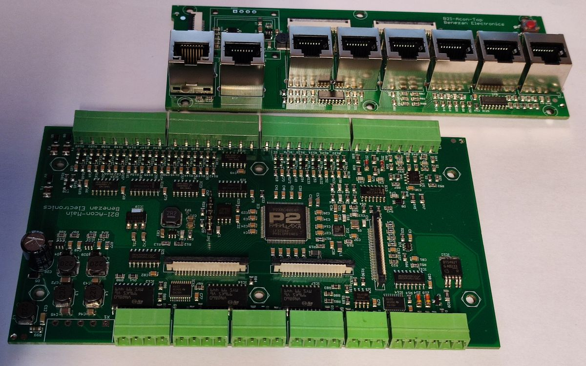
I'm currently designing a replacement for one of my old P1 based controller boards: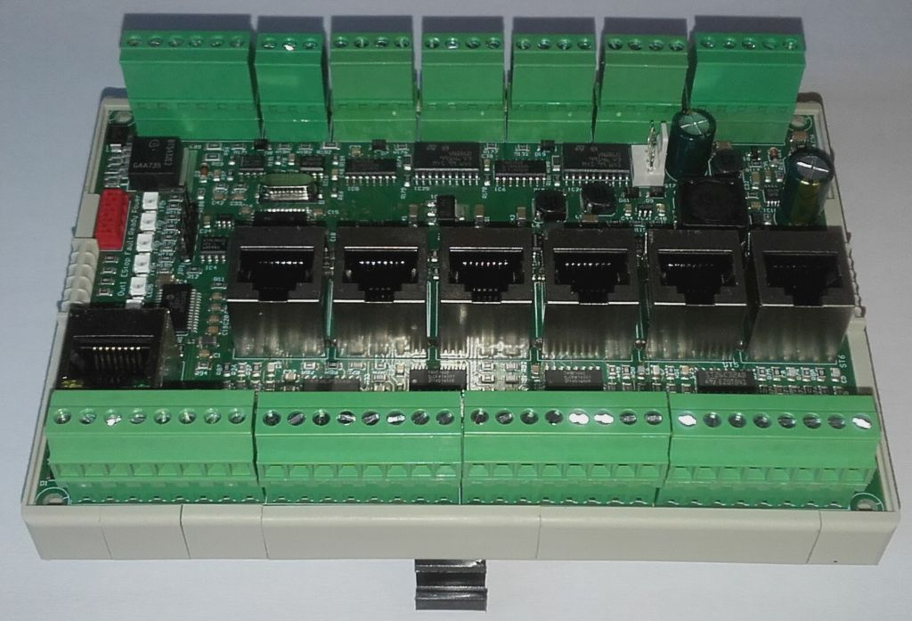
The new one will have similar size and features but with a nicer case instead of an open PCB. I plan to use this DIN rail enclosure. The primary application is CNC control but it will also be suitable for general PLC and motion control. I'll use it for controlling my flight simulator, for example.
Feature wish list:
- 6 axes step/dir interface (optionally 9 axes)
- alternatively 6 ports for high speed RS422 communication (smart abs, SPI, BISS...)
- 18 general purpose 24V inputs (sensors, switches)
- 12 general purpose 24V outputs (solenoids, relays)
- 2 analogue outputs 0..10V
- 2 analogue inputs +/-10V
- 2 PWM outputs 5V
- 1 incremental encoder input (A/B/Z)
- 24V supply
- 100Mbps Ethernet (UDP, IP or custom protocol)
- 128x64 OLED display for status and diagnosis
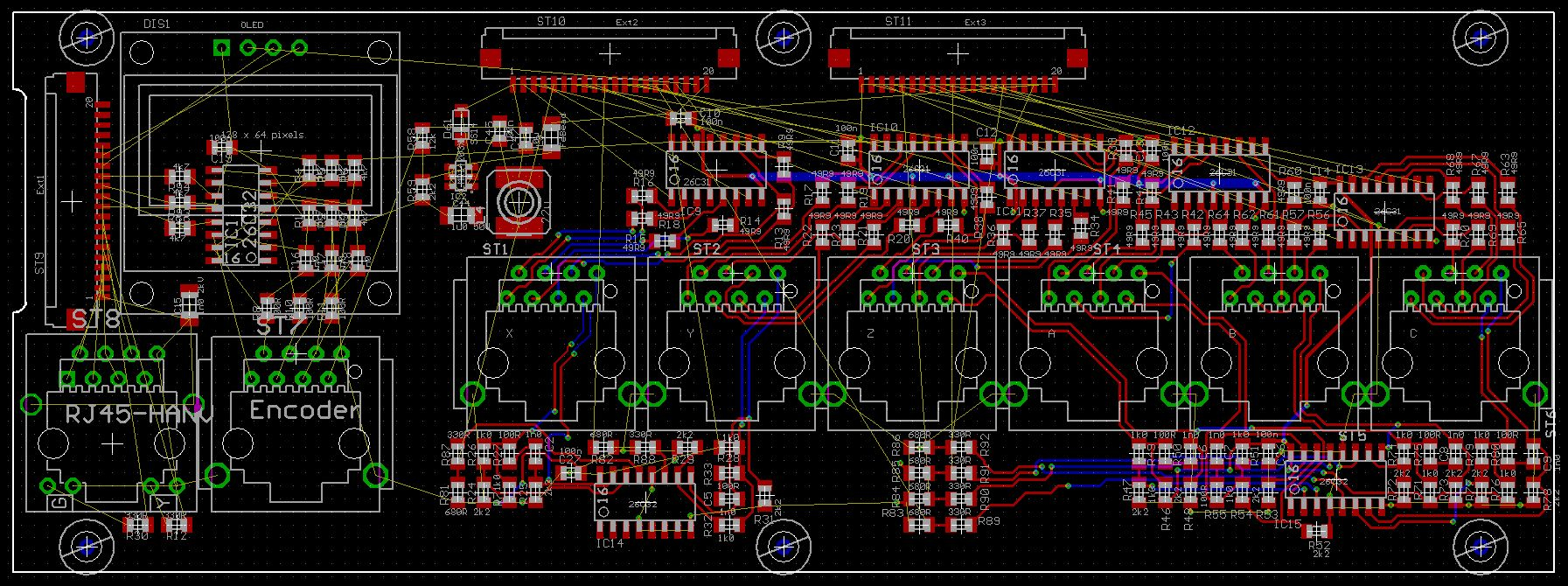
The controller will have two stacked PCBs. The main board at the bottom will hold the P2 and the 24V IOs. The upper board is for the Ethernet, encoder and axis ports. The upper board can be modified to fit special needs in the case customers request it. For example I could add more IOs or more axes by multiplexing some of the slower signals to save P2 pins.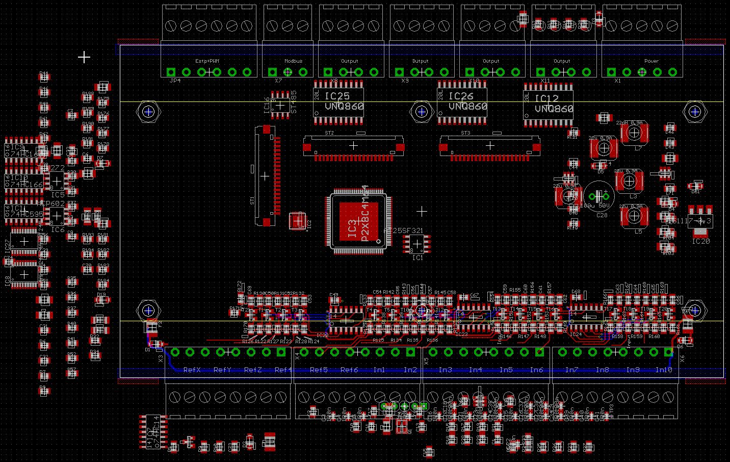
The CNC controller will be a commercial product running proprietary code that I won't disclose. But if the hardware turns out to look interesting for somebody else's project I might sell the boards for the production cost and provide some sort of "skeleton" code to handle the IOs. If required the upper board could even be replaced with a patch field / breakout board for custom circuits. Not as versatile as the P2 EVAL board but better suited to industrial applications.
Comments
very nice!
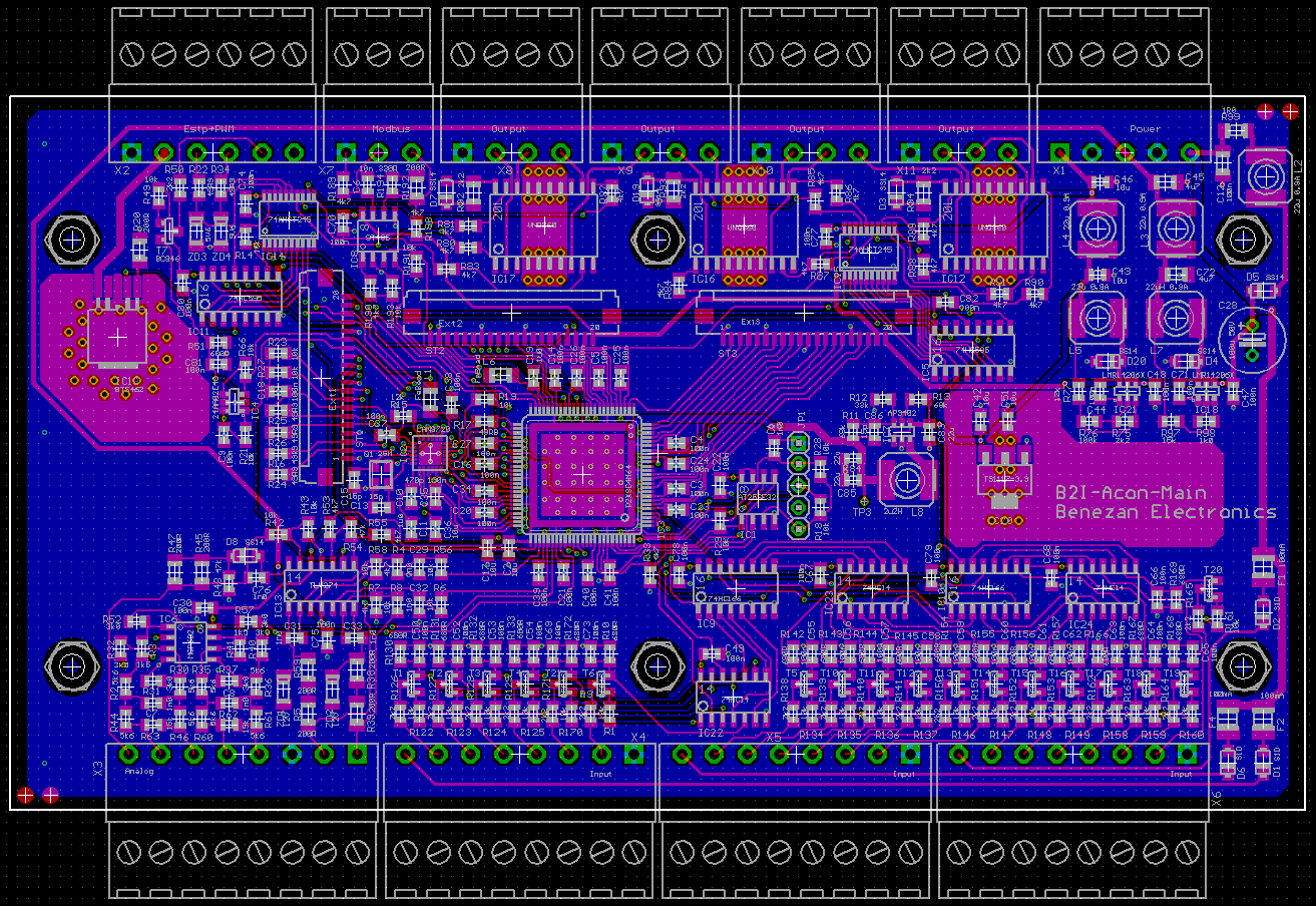
Layout of the main board finished.

My friend Ingolf: "The board is almost empty. You should add some more features."
Mariss: "I hate the color of green."
My excuse: "The enclosure dictates the board size."
If there is a free pin, you may add a microphone to program the plc verbally
Amazing PCB layout work.
Question: how do you protect the 24 VDC output power from random noise, voltage spikes, RF coupling, and all the rest ?
Follow on: how are the input I/O control lines protected, buffered and filtered ?
and how are the output I/O signals amplified and protected ? TIA...
I'm not sure what you mean with "24 VDC output power". Outputs are short circuit protected and have an internal voltage clamp so that they can directly drive inductive loads like solenoids or relays without getting damaged by voltage spikes. I use automotive lamp drivers (VNQ860) that already have full protection built in (overheat, overcurrent, reverse voltage).
For the inputs I use a special circuit that is effectively a constant current sink combined with an RC low pass filter and schmitt trigger. It takes any voltage from 5 to 60V as high and everything <5V as low with a reaction time of ~1ms. Proximity sensors can be used without shielded cables.
Yesterday, I assembled the PCBs.
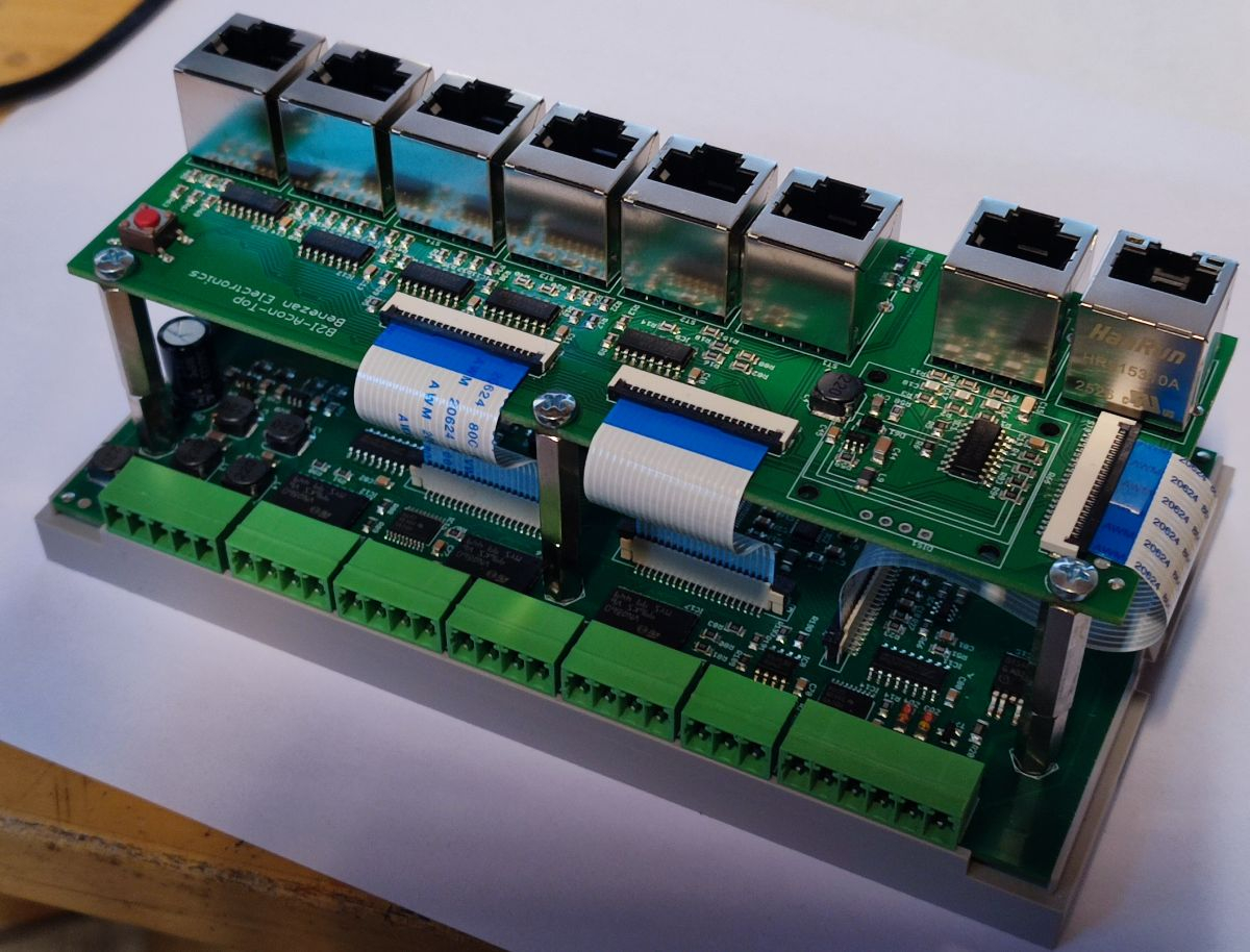
Those FFC cables save a bit of money, space and weight but I don't like the assembly at all. I'm always scared to break something and never sure if the connectors are tight and locked.
The cutouts for the upper board and the OLED display are still missing.
Wow. Very nice!
Very nice! those DIN rail enclosures are great for that. what brand is yours. I'd only seen ones with dividers in not-always-great positions, would prefer what you have with one wide open slot top and bottom.
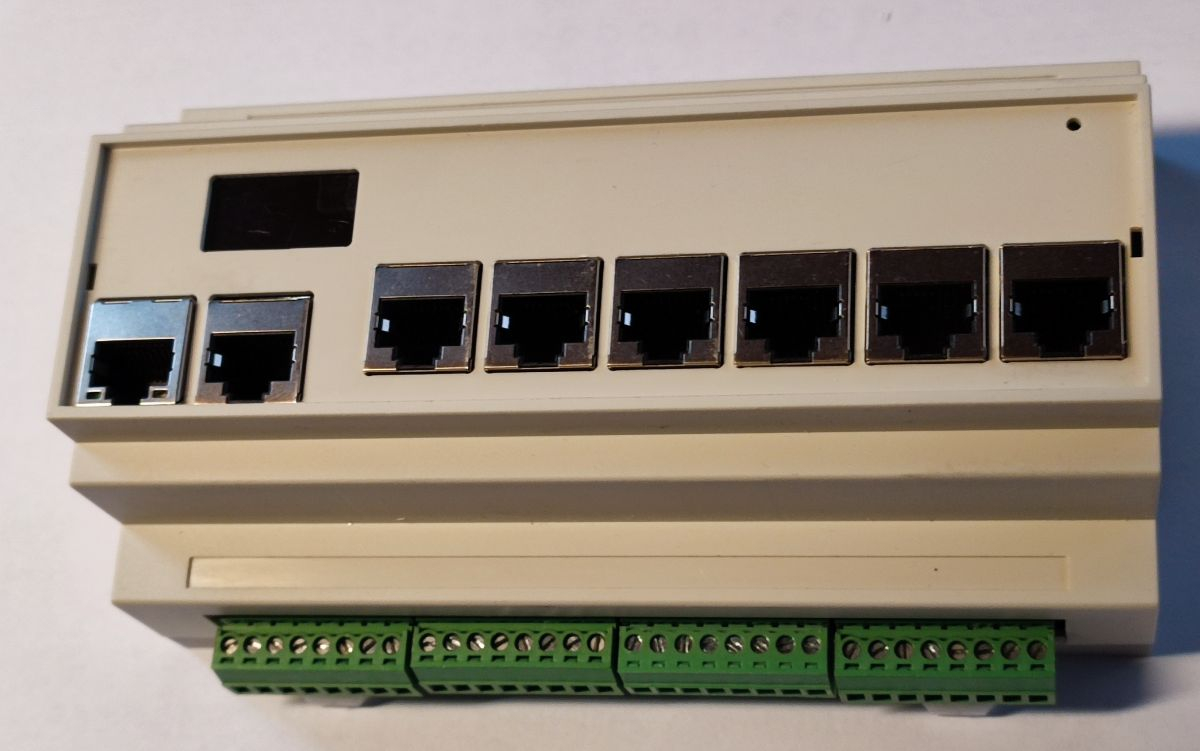
The link to the enclosure manufacturer is in post #1. The BRT-80005-A1 has slots for the green terminals on both sides while the -A3 version has no cutouts. There is a transparent acrylic cover on the top side but it's of bad quality (unequal thickness causes distortions and rainbow reflexions). I will replace that with a custom made front panel. The inner board fixtures (see drawing) are also quit sub-optimal for my case. Standard M3 spacer posts also don't fit into the screw holes but that can be fixed with little effort.
BAHAR offer customization to their enclosures like laser cutting and screen printing but I like to keep the enclosure itself standard and rather add customized panels which can easily be exchanged for different variants of the PCBs if customers requirements change.
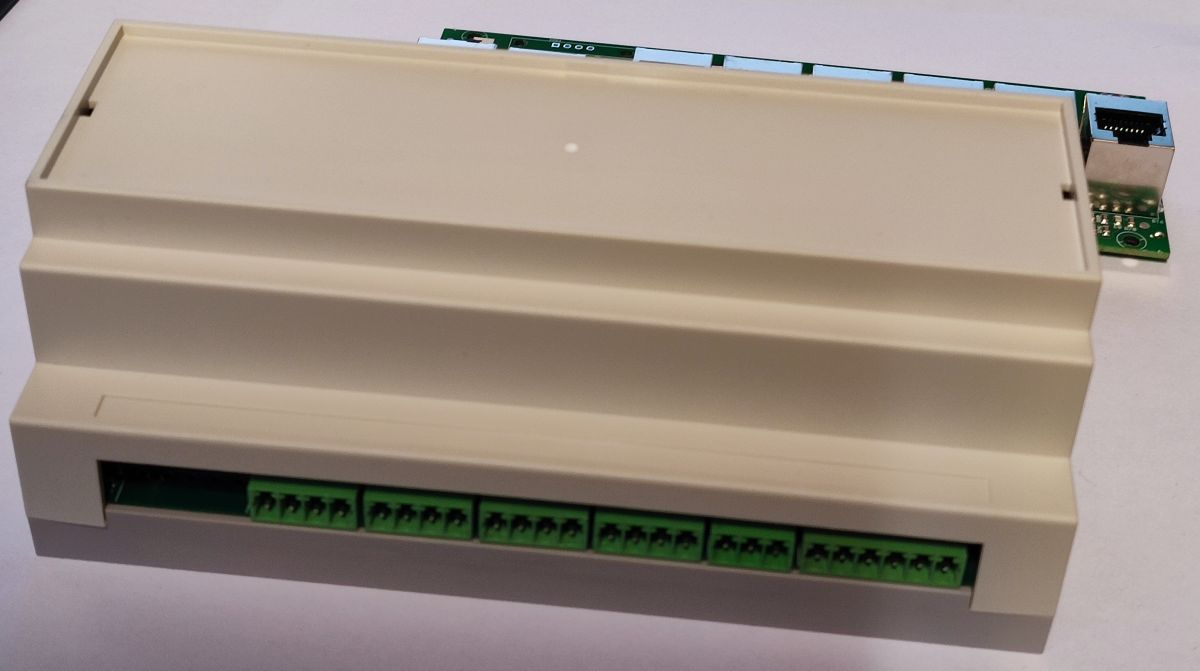
Today, I've machined the top cover.
I've made some mistakes regarding the measurements of the enclosure. It's not exactly a rectangular box but has a slightly truncated pyramid shape to help extracting it from the injection mould. This means it gets narrower towards the top and the upper PCB doesn't fit exactly. I also have to move the display slightly inbound.
Nice . I’m starting to like rj45 for connecting things too.
Guess got the idea from @refaQtor …
I use RJ45 cables since 2006 for almost everything where up to 4 twisted pairs are sufficient:
Here's a RJ45 vibration test:
I use many, many RJ45 connectors since ~20 years in hundreds of machines and never had a single problem that could not be explained by excessive abuse, except...
I just had that broken tab thing on a Beckhoff system. They reported intermittent problems. It looked like someone had broken the tab but shoved the connector in anyway.
Puny components and fat-fingered maintenance people = not good.
"Industry needs Mack trucks, not Ferraris" - Dick Morley "father of the PLC"
The first smoke test was successful. No smoke, the voltage regulators work as expected, digital IO and display are OK.
Next items to check: Ethernet, step/dir signals and encoder input.
The layout needed some corrections: I forgot some pullup/pulldown resistors, outline needs to be some 0.1mm smaller
These oled displays burn out pretty quick. Do you cater for this like for example it's on when it's needed and (mostly) off at all other times ? The more I think about this controller the more I want it despite the fact that I don't actually need it for anything in particular. No smoke is only good when no smoke is expected .
.
The OLED display is rated for 10,000h life time @25°C and full brightness and 50,000h at half brightness. That's not much for industrial use and I guess it gets worse at higher temperature.
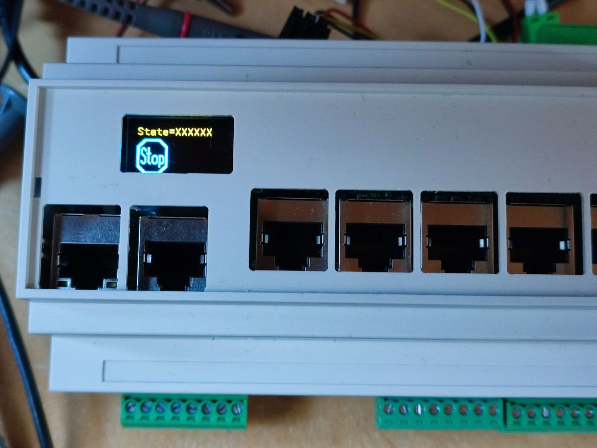
The display is not really needed except for diagnosis during installation. All I need is to display if the Ethernet link status is OK. If a hidden button is pressed with a pin a diagnosis mode is entered where the state of the inputs and outputs are displayed. If you press the button longer a special pairing mode is activated where the controller responds to broadcasts over ethernet so that the IP address can be set. The display acknowledges if everything went OK. After the connection is established everything can be viewed from the PC even with the display hidden or inoperative.
But thanks for the hint. I think I'll implement a "screen saver" which dims the display after some seconds if nothing changes.
But I like those little displays. They don't cost much and are a nice eye-catcher. And for the support it's much easier to ask "do you see an OK-symbol" than "is the green LED at the RJ45 connector lit permanently and the yellow one is flashing?" Error messages can be displayed in plain text instead of "the second red LED flashes twice per second?".
BTW, I've found a note in the manual about "burn-in" vs. "image sticking".
So it's no real "burn-in" but should be reversible and a svreen saver should fix it.
That was the same on CRTs and Plasmas too. Permanent burn-in is very long term. It's basically unequal ageing from unequal use of pixels. Even the fancy "Quantum Dot" LCDs are heavily using phosphors now too. If you want rich high contrast colour and wide viewing angles then phosphors are it.
OLEDs seem to be very similar behaving to phosphors. I don't know anything about the chemistry but I wouldn't be at all surprised if the two are related here.
The contrast register in the OLED controller IC controls the LED current. It can be set from 0 to 255 and was already at the default of 127 which means half brightness and 50,000h expected lifetime. Thats 5.7 years at 25°C. The sensitivity of the human eye is logarithmic. Full brightness is only required in direct sunlight. 1/4 brightness is totally OK indoors and even contrast=1 is still visible. So with a screen saver that dims from contrast=127 down to 32 the display should survive the warranty period of 2 years even at 45°C.
The huge pure LED signage boards won't be immune either. They will be using lighting type LEDs - and lighting LEDs are all native blue only. So they also need phosphors to tune their colours.
The schematics needed some small fixes. A series resistor to make an input 5V tolerant was too small. The current injected into the body diode caused two neighbouring DAC pins to fail completely (luckily not irreversibly). They saturated to 3.6V and 0V regardless of the DAC value. I changed the series resistor to a voltage divider to fix this.
The encoder input, the Ethernet interface and the step/dir outputs are also working, now.") And I've implemented the screen saver.
And I've implemented the screen saver.
Slowly but consistently I'm making further progress... Yesterday I've managed to get the servo motors running. They are connected to both the step/dir signals and via MODBUS. Step/Dir is good for realtime positioning commands while MODBUS is used for status monitoring, configuration and diagnostics.
One major benefit of this combination is that I can shutdown the drives completely by cutting mains power for an emergency stop or safety door open event. The absolute encoders of the servo motors are being powered on backup batteries and keep their values even when the drives are powered down. So I can read the encoder position over MODBUS after a power cycle and don't have to repeat the homing procedure. This even works when the axes of the machine happen to be moved manually while the servos are off.
The next thing I'd like to implement is support for "assisted manual tuning" of the servo control parameters. This is important for CNC machines because automatic tuning often doesn't provide satisfying results because, for example, X and Y axes have different inertia which results in different gain settings and different following errors. The result is that circles become elliptical and the tool trajectory gets distorted. With manual tuning the parameters can be fine tuned in a rather connected instead of axis-seperated way so that the following error matches between diffenrent axes.
But manual tuning can be very time consuming with digital drives. The tuning software, especially for cheap Chinese drives, if it exists at all, is often not very user-friendly. So you end up having to type in parameters via the front panel with only 4 buttons, test them, judge the results and iterate over and over, again.
My idea is to send stimulus to the drive using step/dir signals with a trapezoid velocity profile moving the motor back and forth repeatedly. A device similar to an oscilloscope displays nominal and actual position or following error in real time. Instead of polling the information with software from the drive it uses taps to the hardware signals. So it works independently of the software provided (or not provided) by the manufactutrer.
The actual tuning can then be performed by moving sliders in the GUI of my CNC control software which transmits the values over MODBUS. This provides a nearly "analogue" feel like in the old days where servo drives had potentiometers to tune the PID loop gains. Seeing immediate response on the scope display this procedure only takes seconds instead of hours.
I'm the complete opposite because I detest the step/ dir method. It's like washing your feet with socks on.
We have arguably the most powerful closed loop potential in the P2. I am sticking with analog command. 5V UPS to the P2 to maintain encoder count during power-down is a no-brainer.
There are countless CNC machines in need of retrofitting of a control system only. The existing servo drives/ motors are fine.
Potentiometers on servo drives") Man, those were the days. I still have machines, here with those...never an issue and they are 30+ years old. The industry has arguably gone backwards because these machines have a tach feedback from the motor and a precision rack & pinion along the bed for position feedback. The control always knows the position of the important bit
Man, those were the days. I still have machines, here with those...never an issue and they are 30+ years old. The industry has arguably gone backwards because these machines have a tach feedback from the motor and a precision rack & pinion along the bed for position feedback. The control always knows the position of the important bit
What do we have today? The controller only knows the rotor angle of the motor. Decouple the motor from the transmission and lay it on the side of the machine, run a program and the controller is oblivious to the fact that nothing moved. How ridiculous can you get.
"Oh we have DSP and FOC today" So what? We are getting to the wrong position more accurately????
We need to cut the BS and get back to what not only works but that can also be easily maintained.
Sorry for drifting off-topic and ranting but I'm one those guys who get the 2am phone call to a dead production line. The big guns are deliberately making things more complicated and just like the Emperor's New Clothes, design engineers are lapping up this horse doo-doo.
Hehe, I'm not seeing any "sorry" in that messaging.
It's certainly cool to be able to log error ... but if it's a positional profile then positional demand is all you need.
On the other hand, having toque control is sometimes a useful feature. Eg: I now own a converted EV (From a 1993 Ford Festiva body) that I purchased already converted. It is fitted with a second-hand DC motor and drive lifted from an even older Nissan forklift. The motor/drive combo is underpowered and was designed for operating a hydraulic pump rather than direct mechanical to the road. The motor is fitted direct to the 5-speed manual gearbox, clutch/flywheel removed. The drive is simplest voltage control and has a jerk "feature" for kicking off the hydraulic pump. As such, it has issues in its new home in the Festiva. I've learnt the best way to start off is to use my left foot to hold the breaks on until the jerk is over. Otherwise it's embarrassing trying to back out of a car park for example.
Having straight toque control would do wonders for smoothing out the ride as a whole. I've pondered looking around for a replacement kit but just know it'll be expensive. The car was cheap so I'm not that keen on over-spending.
On the positive side, I've now also learnt that LFP cells are rugged enough to handle overcharging without ill effects. I was topping up each cell manually, using a bench-top power supply, when I accidentality let one go too far. It was taking a long time and I needed to go inside so left it charging unattended. Needless to say I got back to find the BMS squawking and the bench-top supply was no longer in current-limit. The cell had stopped taking any current at all. So no untoward reactions. I unplugged it all quickly. I didn't get a voltage reading as that bench-top readout doesn't work. Something north of 4 Volts.
That cell has been just fine ever since. The battery balancing got me the extra range I was after.
@evanh
The big guns don't care about you losing a contract because your production line died.
Torque control.... absolutely it's all I ever do. Between my MCU and motor, I only want a transconductance unit. I set the current scaling and end of story. If the drive needs replaced and I don't have the same one available, I can grab any other brand to get the line back up and running.
From a control perspective, we need to handle camming, gantry-mode and all kinds of electronic gearing. A master axis might already be up to speed and the slave needs to ramp up and eventually sync. Prop is perfect for this.
I lurk over at PLCtalk.net and it is painful to read what those guys have to go through to solve the simplest problem and they are brainwashed to believe that there is no better approach.
Well, they aren't going to throw out the investment because someone else in the forum says so. Besides, it's worth some pain to make it work in Ladder. Then any sparky can come along and make sense of the machine.