@"Christof Eb." said:
Hi,
perhaps this is again my not-knowing...
As far as I know, you can only use the streamer for data movement, if your code is executing from cog or lut memory. I don't think, that inline asm is loaded into cog memory?
Streamer and Fifo aren't entirely the same thing. The RDFAST instruction starts up the Fifo independent of the Streamer. It allows other Cog instructions like RFLONG access to the Fifo's FIFO.
Inline assembly is by default loaded into cogRAM just before it is executed. So not entirely inline as such. This is quite important when wanting to use the Fifo within the "inline" Pasm2 code. The Spin2 interpreter uses the Fifo itself. And Flexspin executes natively as hubexec which also requires the Fifo.
The "counter := @BHwindow" worked, @evanh , thank you. Attached is a test program to be run in debug mode for the scope displays - a blackman harris window is applied to a sine wave. The window is applied to a polar signal, as being easier to do when preloading the cordic engine. My attempt to do it on a cartesian signal didn't produce the correct result - I was not getting all the correct values out of the cordic, due to twice the number of multiplies, the 8 cycle pattern was broken. I may return to that - I expect it needs pacing to 16 cycles.
@"Christof Eb." , my inline assembly methods use the "org ... end" form which means the code will be loaded into cog ram before execution. Had I used " orgh ... end", then the code would execute from hub ram. (See "In-line PASM Code" section of the Spin2 manual) In the changes section it also states:-
PUB/PRI methods now support ORGH (hub) inline PASM code, in addition to ORG (cog) inline PASM code.
○ Like ORG, ORGH loads the first 16 local long variables from hub RAM into cog registers, executes
the inline code, and then updates the registers back to hub RAM.
○ Unlike ORG inline code, ORGH inline code does not load code into cog registers $000..$11F, but can
be up to $FFFF instructions long, since it stays and executes in hub RAM.
○ ORGH allows inline PASM code without interfering with the $000..$11F cog register space, So, those
cog registers can be used entirely for stay-resident code, like interrupt service routines or frequentlycalled fast PASM routines.
As you can see in the window demo here, both the "sine" and the "polwin" method in the dsp library use the FIFO successfully
Streamer and Fifo aren't entirely the same thing. The RDFAST instruction starts up the Fifo independent of the Streamer. It allows other Cog instructions like RFLONG access to the Fifo's FIFO.
Does this mean, that when DDS from LUT to DAC is used, the STREAMER is used but not the FIFO and therefore code can in parallel be executed from HUB?
Inline assembly is by default loaded into cogRAM just before it is executed. So not entirely inline as such. This is quite important when wanting to use the Fifo within the "inline" Pasm2 code. The Spin2 interpreter uses the Fifo itself. And Flexspin executes natively as hubexec which also requires the Fifo.
OK, sorry, I was not aware, that SPIN2 loads inline asm into cog ram.
@"Christof Eb." said:
Does this mean, that when DDS from LUT to DAC is used, the STREAMER is used but not the FIFO and therefore code can in parallel be executed from HUB?
I spotted the scope plot of the windowing method didn't look quite right. The whole idea is for the waveform to start at 0 and end at 0. The scope trace above doesn't look like it does that. However, it was only the two traces being set on AUTO scaling. When I defined the max and min plot scale, then the two traces did show zero ends:-
The production of the window in the DAT section was not laboriously typed in. It was a matter of:-
1. Producing the 1024 sample window in a spreadsheet
2. In another column, scaling up the window ( samples in the range 0-1) to the point where the first sample was just under 1. The window happened to peak at 16384
3. In another column, converting that scaled window to integers
4. In a column to the left of the integers, putting 'word' in every row (or 'long' or 'byte' or whatever you need )
5. These two columns can then be directly copied and pasted into the editor in Pnut or Spin Tools
Use rdfast #0, ##BHwindow instead of #BHwindow. The double # tells PASM2 it’s an address, not a value. Make sure the code runs from COG or LUT memory since rdfast cannot stream from Hub memory directly.
A small nit-pick: ## tells PASM2 that it's more than 9 bits (or more precisely, that it needs an AUGS or AUGD instruction to encode), not necessarily that it's an address. Addresses are more than 9 bits, so they do often fall into the "needs double #" category, but so do other large constants. And a few jump style instructions can actually hold an address without an AUGD/AUGS, so don't need two # in them.
My approach, which seems to work (using the edge module with PSRAM), is to fill a small chunk of samples from the ADC in hub ram, and between each sample do quite a bit:
(1) copy these chunks to a large buffer in PSRAM (burst moves work very efficiently - 100 MB/s in my case)
(2) move blocks from the large PSRAM buffer to a ring buffer on demand from a signal processing cog
This allows the signal processing cog (or cogs, as needed) to work "at its leisure" on ring buffer data while the first cog is flowing data in to PSRAM. This accounts for the fact that in my case, the signal processing code can take a variable amount of time depending on how many interesting features are in a segment of data.
It seems awkward to do this (and it is complicated to manage), but it allows me to keep one continuous segment of data in PSRAM, and as needed flush it as a file to an SD card for later analysis on a PC. In my case, this segment is 6 MB, so HUB RAM cannot be used for the large buffer.
The primary limitation is the capacity of PSRAM. In my case (which depends on sampling rate, number of channels, and sample bit depth) I can only store a maximum of 15 seconds of data in PSRAM.
I do not need my code to work on a continuous signal - I can fill the PSRAM buffer and then crunch using the signal processing cog, pulling the data into the ring buffer as needed. I have not thought about how to make this approach work on continuous signals, although the ring buffer approach seems amenable. In an SDR app that processes continuous signals, I think that performing everything on-chip could be done with smaller buffers, but am not sure.
I use Spin2 and use the hub memory only, so this is far from the most efficient way -- e.g., some day I could work on storing the small chunks in COG/LUT RAM. But even with this slow implementation, I have over 1000 clock cycles between each ADC sample to do the buffer management.
To build this, I relied on experiments using the system counter, which is invaluable. I've been using flexspin, thinking that this runs faster than interpreted byte codes (?).
The reason I like the P2 for this is I can implement true hardware threads in a shared memory architecture (I looked carefully at dual-core STM Cortex chips and in my view it looked picky and painful do to anything close to what you can do on the P2). As a result, so far I have not needed a scheduler. However, in this regard, I am curious if others have played with SPIN2 cooperative tasks.
I'm working towards a bandpass filter for use in a software defined radio whose low and high cut-off frequency can be changed by the user whilst listening to the radio. The FFT fast-convolution filter I intend to use requires the bandpass filter impulse response as one of it's inputs.
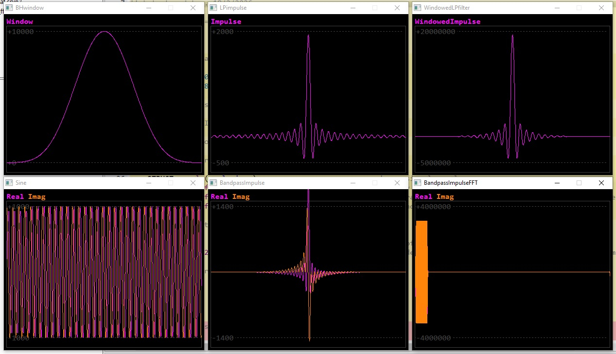
I made a demo of producing that impulse response on the P2. I've used SPIN2 floating point for now, so as to be sure of not losing information with integer rounding. These are the debug plots it produces:-
Top line, left to right: The Blackman Harris window, The lowpass filter impulse response, The windowed lowpass filter impulse response
Bottom line, left to right: An iq sinewave, The windowed lowpass filter impulse response converted to bandpass impulse response by multiplying by the sinewave
I was gratified that the results look to be identical to the filter I produced for a LabView receiver, written quite a few years back.
I had to update @ersmith 's BinFloat.spin2 library from the obex to allow it compile under Spin2 v52 (Two names - exp and exp10 - are now reserved words). I removed methods that are now built into Spin2.
This is a bit more interesting - the bandpass filter impulse response is passed through an FFT, ready for multiplying with the FFT of the signal input, as part of the FFT fast convolution filter. All this code would be executed only if the user changes the upper or lower cut-off frequency of the filter. The final waveform produced gives some idea of the filter shape:.
The variables Flow and Fhigh may be changed by editing and the bandpass filter FFT is observed to change accordingly. Note the desirable flat top and sharp vertical sides. The left hand side of the plot is 0Hz, the right hand side is 48kHz.
Bob
The code above is inefficient, it's for demo purposes - just feeling my way here step by step. The final code would have far fewer repeat loops to speed things up and buffers would be reused where possible to reduce memory size.
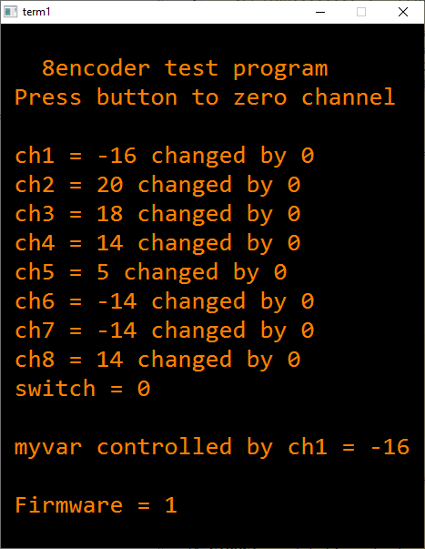
A radio with a few knobs to operate key controls like volume, filter frequencies, band change etc. is much more ergonomic than one with buttons only. I bought an 8encoder made by M5stack, China as a quick way of adding 8 knobs and a slide switch. Each knob has a pushbutton. The interface is i2c. The unit is small and the knobs are a bit close together for western 'sausage' fingers, but for experimenting it's fine. Attached is a SPIN2 driver I wrote for 8encoders fitted with version 1 firmware, which includes a test program. It displays:-
I notice that the low-cost encoders used in the 8encoder have a click action that won't allow the encoder switches to stop at odd number positions. If that's a problem, then dividing the count by two is one way of fixing the issue.
I've noticed before, that those switches are not proper quadrature switches, but two transitions are close, and they are not rasterized. I then only took one transition, to have a symmetrical signal. Maybe there is the step/direction thinking still prevalent..
It's just taking action and missing a strategy.
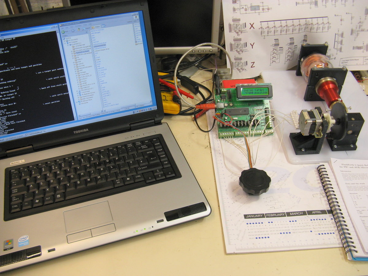
Quite a while back, I helped make a magnetic loop antenna for a friend. My job was to create the stepper motor driven capacitor and the desktop controller. The controller had a knob to set the capacitor, which was a cheap encoder with a click stop action. This was really irritating in this application, so I dismantled the encoder and took out the click spring. This also resulted in the operator being able to step the control by one easily. I programmed the pic controller in multitasked flashforth, I remember. Because the knob had to set the capacitor in the range 0 - maybe 20000, I arranged that the knob increment was variable, depending on how fast the knob was rotated. It was either x^2 or x^3, I can't remember - but it felt quite natural, you could spin up large numbers quickly or slowly increment by 1. I was quite proud of that project.
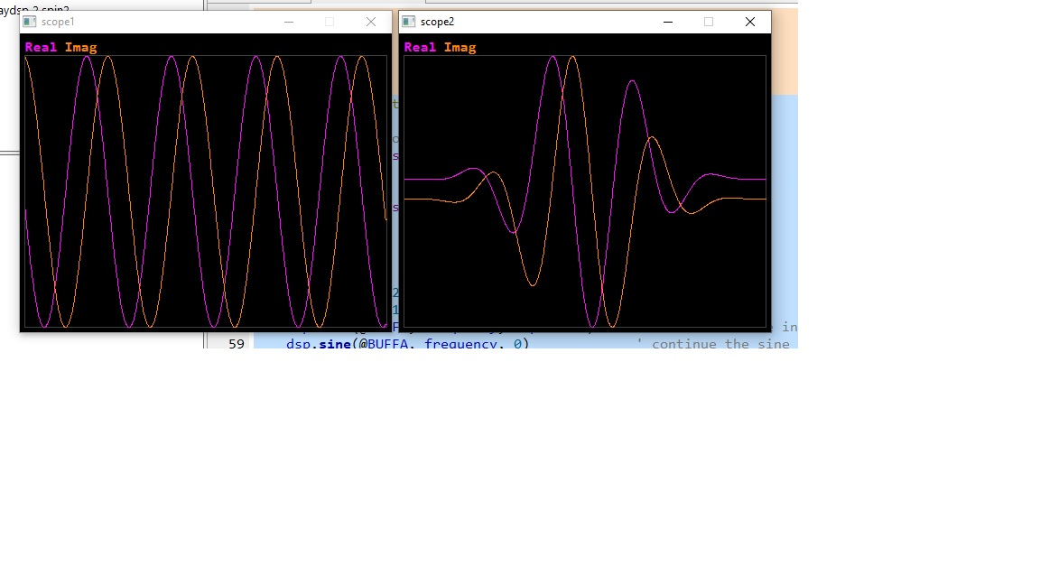
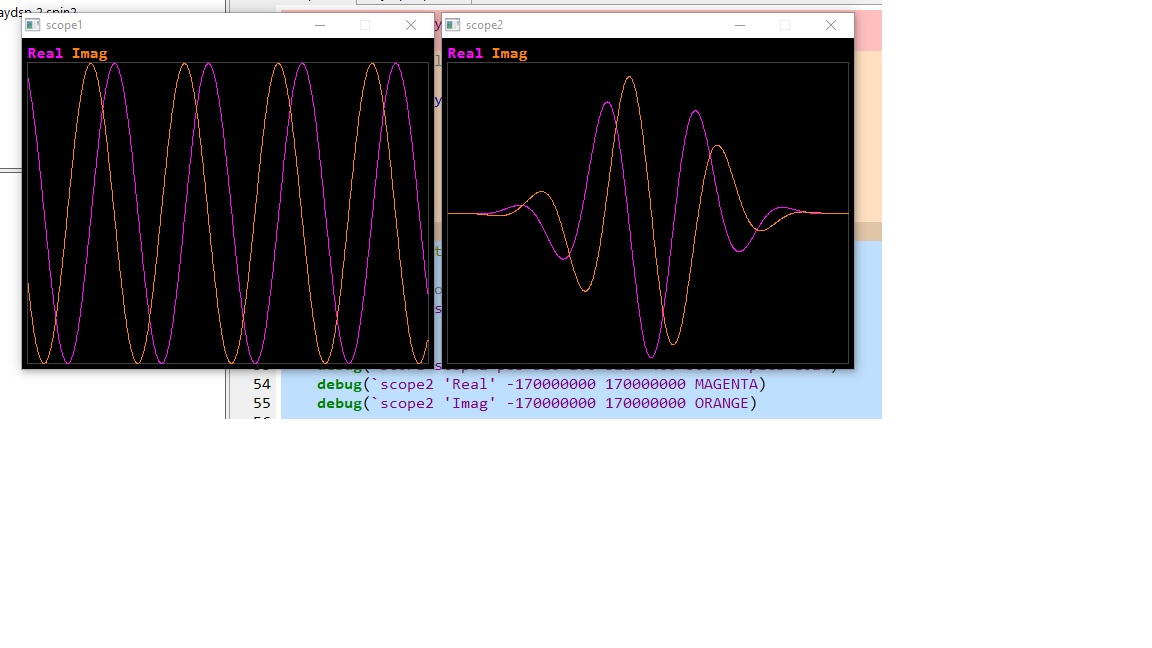
I added a gain (scaling) method to the dsp library. How to vary the amplitude of a signal by small increments? Dividing or multiplying by an integer is far too coarse. The answer is to multiply the amplitude by a fraction made up of two integers dividend/divisor. In my test, divisor is held constant at 100, and dividend is a variable. The two debug scope windows show the original 100Hz sinewave and that signal after gain control has been applied. It can be seen that the signal doesn't glitch, when each buffer receives a gain change of only 1/100.
Why use polar coordinates? Because each sample is made of magnitude and angle. Magnitude is always +ve. QMUL and QDIV will only work with +ve data. I'm working on a gain method that operates on cartesian coordinates, which involves signed to unsigned to signed conversion.
@bob_g4bby said:
QMUL and QDIV will only work with +ve data. I'm working on a gain method that operates on cartesian coordinates, which involves signed to unsigned to signed conversion.
The front end of my software define radio converts a 48 khz wide chunk of the short wave bands to a baseband iq signal. However, due to tiny imbalances in the circuitry, the i and q channel into the adcs of the HDaudio module have small dc offsets placed on them. The dc offsets are undesirable, leading to a permanent, small phantom signal in the middle of the spectrum display. So I've been experimenting with estimation and removal of the dc offsets. I've coded a solution in Spin, prior to writing a faster method with inline Pasm. The attached code shows a slow iteration to a stable point, eliminating the DC offsets.
The scope window on the left shows the iq signal with a bad dose of dc offset, the window on the right shows the signal having been cleaned up.
For the upcoming FFT convolution filter I'm working on, I've made the array size of the signals etc. a parameter of the methods, rather than a constant. Here's the latest version of the library with some test programs


Comments
Streamer and Fifo aren't entirely the same thing. The RDFAST instruction starts up the Fifo independent of the Streamer. It allows other Cog instructions like RFLONG access to the Fifo's FIFO.
Inline assembly is by default loaded into cogRAM just before it is executed. So not entirely inline as such. This is quite important when wanting to use the Fifo within the "inline" Pasm2 code. The Spin2 interpreter uses the Fifo itself. And Flexspin executes natively as hubexec which also requires the Fifo.
The "counter := @BHwindow" worked, @evanh , thank you. Attached is a test program to be run in debug mode for the scope displays - a blackman harris window is applied to a sine wave. The window is applied to a polar signal, as being easier to do when preloading the cordic engine. My attempt to do it on a cartesian signal didn't produce the correct result - I was not getting all the correct values out of the cordic, due to twice the number of multiplies, the 8 cycle pattern was broken. I may return to that - I expect it needs pacing to 16 cycles.
@"Christof Eb." , my inline assembly methods use the "org ... end" form which means the code will be loaded into cog ram before execution. Had I used " orgh ... end", then the code would execute from hub ram. (See "In-line PASM Code" section of the Spin2 manual) In the changes section it also states:-
PUB/PRI methods now support ORGH (hub) inline PASM code, in addition to ORG (cog) inline PASM code.
○ Like ORG, ORGH loads the first 16 local long variables from hub RAM into cog registers, executes
the inline code, and then updates the registers back to hub RAM.
○ Unlike ORG inline code, ORGH inline code does not load code into cog registers $000..$11F, but can
be up to $FFFF instructions long, since it stays and executes in hub RAM.
○ ORGH allows inline PASM code without interfering with the $000..$11F cog register space, So, those
cog registers can be used entirely for stay-resident code, like interrupt service routines or frequentlycalled fast PASM routines.
As you can see in the window demo here, both the "sine" and the "polwin" method in the dsp library use the FIFO successfully
LOL, I failed Spin's
:=syntax too. I get that wrong every time I start a new Spin project. First compile has me fixing them.Does this mean, that when DDS from LUT to DAC is used, the STREAMER is used but not the FIFO and therefore code can in parallel be executed from HUB?
OK, sorry, I was not aware, that SPIN2 loads inline asm into cog ram.
Yep.
I spotted the scope plot of the windowing method didn't look quite right. The whole idea is for the waveform to start at 0 and end at 0. The scope trace above doesn't look like it does that. However, it was only the two traces being set on AUTO scaling. When I defined the max and min plot scale, then the two traces did show zero ends:-
The production of the window in the DAT section was not laboriously typed in. It was a matter of:-
1. Producing the 1024 sample window in a spreadsheet
2. In another column, scaling up the window ( samples in the range 0-1) to the point where the first sample was just under 1. The window happened to peak at 16384
3. In another column, converting that scaled window to integers
4. In a column to the left of the integers, putting 'word' in every row (or 'long' or 'byte' or whatever you need )
5. These two columns can then be directly copied and pasted into the editor in Pnut or Spin Tools
Message deleted
A small nit-pick:
##tells PASM2 that it's more than 9 bits (or more precisely, that it needs an AUGS or AUGD instruction to encode), not necessarily that it's an address. Addresses are more than 9 bits, so they do often fall into the "needs double #" category, but so do other large constants. And a few jump style instructions can actually hold an address without an AUGD/AUGS, so don't need two # in them.My approach, which seems to work (using the edge module with PSRAM), is to fill a small chunk of samples from the ADC in hub ram, and between each sample do quite a bit:
(1) copy these chunks to a large buffer in PSRAM (burst moves work very efficiently - 100 MB/s in my case)
(2) move blocks from the large PSRAM buffer to a ring buffer on demand from a signal processing cog
This allows the signal processing cog (or cogs, as needed) to work "at its leisure" on ring buffer data while the first cog is flowing data in to PSRAM. This accounts for the fact that in my case, the signal processing code can take a variable amount of time depending on how many interesting features are in a segment of data.
It seems awkward to do this (and it is complicated to manage), but it allows me to keep one continuous segment of data in PSRAM, and as needed flush it as a file to an SD card for later analysis on a PC. In my case, this segment is 6 MB, so HUB RAM cannot be used for the large buffer.
The primary limitation is the capacity of PSRAM. In my case (which depends on sampling rate, number of channels, and sample bit depth) I can only store a maximum of 15 seconds of data in PSRAM.
I do not need my code to work on a continuous signal - I can fill the PSRAM buffer and then crunch using the signal processing cog, pulling the data into the ring buffer as needed. I have not thought about how to make this approach work on continuous signals, although the ring buffer approach seems amenable. In an SDR app that processes continuous signals, I think that performing everything on-chip could be done with smaller buffers, but am not sure.
I use Spin2 and use the hub memory only, so this is far from the most efficient way -- e.g., some day I could work on storing the small chunks in COG/LUT RAM. But even with this slow implementation, I have over 1000 clock cycles between each ADC sample to do the buffer management.
To build this, I relied on experiments using the system counter, which is invaluable. I've been using flexspin, thinking that this runs faster than interpreted byte codes (?).
The reason I like the P2 for this is I can implement true hardware threads in a shared memory architecture (I looked carefully at dual-core STM Cortex chips and in my view it looked picky and painful do to anything close to what you can do on the P2). As a result, so far I have not needed a scheduler. However, in this regard, I am curious if others have played with SPIN2 cooperative tasks.
@bob_g4bby, thanks for starting this discussion!
Paul
I'm working towards a bandpass filter for use in a software defined radio whose low and high cut-off frequency can be changed by the user whilst listening to the radio. The FFT fast-convolution filter I intend to use requires the bandpass filter impulse response as one of it's inputs.
I made a demo of producing that impulse response on the P2. I've used SPIN2 floating point for now, so as to be sure of not losing information with integer rounding. These are the debug plots it produces:-
Top line, left to right: The Blackman Harris window, The lowpass filter impulse response, The windowed lowpass filter impulse response
Bottom line, left to right: An iq sinewave, The windowed lowpass filter impulse response converted to bandpass impulse response by multiplying by the sinewave
I was gratified that the results look to be identical to the filter I produced for a LabView receiver, written quite a few years back.
I had to update @ersmith 's BinFloat.spin2 library from the obex to allow it compile under Spin2 v52 (Two names - exp and exp10 - are now reserved words). I removed methods that are now built into Spin2.
Cheers, Bob
I've been modelling the above in a free wysiwyg maths program called Smath Studio - it's been about for years. Here's the Smath file I've written
This is a bit more interesting - the bandpass filter impulse response is passed through an FFT, ready for multiplying with the FFT of the signal input, as part of the FFT fast convolution filter. All this code would be executed only if the user changes the upper or lower cut-off frequency of the filter. The final waveform produced gives some idea of the filter shape:.
The variables Flow and Fhigh may be changed by editing and the bandpass filter FFT is observed to change accordingly. Note the desirable flat top and sharp vertical sides. The left hand side of the plot is 0Hz, the right hand side is 48kHz.
Bob
The code above is inefficient, it's for demo purposes - just feeling my way here step by step. The final code would have far fewer repeat loops to speed things up and buffers would be reused where possible to reduce memory size.
A radio with a few knobs to operate key controls like volume, filter frequencies, band change etc. is much more ergonomic than one with buttons only. I bought an 8encoder made by M5stack, China as a quick way of adding 8 knobs and a slide switch. Each knob has a pushbutton. The interface is i2c. The unit is small and the knobs are a bit close together for western 'sausage' fingers, but for experimenting it's fine. Attached is a SPIN2 driver I wrote for 8encoders fitted with version 1 firmware, which includes a test program. It displays:-
Here's the unit:-
Cheers, bob
I notice that the low-cost encoders used in the 8encoder have a click action that won't allow the encoder switches to stop at odd number positions. If that's a problem, then dividing the count by two is one way of fixing the issue.
I've noticed before, that those switches are not proper quadrature switches, but two transitions are close, and they are not rasterized. I then only took one transition, to have a symmetrical signal. Maybe there is the step/direction thinking still prevalent..
It's just taking action and missing a strategy.
Quite a while back, I helped make a magnetic loop antenna for a friend. My job was to create the stepper motor driven capacitor and the desktop controller. The controller had a knob to set the capacitor, which was a cheap encoder with a click stop action. This was really irritating in this application, so I dismantled the encoder and took out the click spring. This also resulted in the operator being able to step the control by one easily. I programmed the pic controller in multitasked flashforth, I remember. Because the knob had to set the capacitor in the range 0 - maybe 20000, I arranged that the knob increment was variable, depending on how fast the knob was rotated. It was either x^2 or x^3, I can't remember - but it felt quite natural, you could spin up large numbers quickly or slowly increment by 1. I was quite proud of that project.
I added a gain (scaling) method to the dsp library. How to vary the amplitude of a signal by small increments? Dividing or multiplying by an integer is far too coarse. The answer is to multiply the amplitude by a fraction made up of two integers dividend/divisor. In my test, divisor is held constant at 100, and dividend is a variable. The two debug scope windows show the original 100Hz sinewave and that signal after gain control has been applied. It can be seen that the signal doesn't glitch, when each buffer receives a gain change of only 1/100.
Why use polar coordinates? Because each sample is made of magnitude and angle. Magnitude is always +ve. QMUL and QDIV will only work with +ve data. I'm working on a gain method that operates on cartesian coordinates, which involves signed to unsigned to signed conversion.
Cheers, Bob
pub polfractgain(buffin, buffout,dividend,divisor) | counter 'amplify or attenuate polar buffin by the fraction dividend/divisor, polar result in buffout org push ptra mov ptra, buffin mov ptrb, buffout mov counter, #(sigbuffsize/16) fractgain1 setq #31 rdlong array, ptra++ qmul array, dividend qmul array+2, dividend qmul array+4, dividend qmul array+6, dividend qmul array+8, dividend qmul array+10, dividend qmul array+12, dividend qmul array+14, dividend getqx array qmul array+16, dividend getqx array+2 qmul array+18, dividend getqx array+4 qmul array+20, dividend getqx array+6 qmul array+22, dividend getqx array+8 qmul array+24, dividend getqx array+10 qmul array+26, dividend getqx array+12 qmul array+28, dividend getqx array+14 qmul array+30, dividend getqx array+16 getqx array+18 getqx array+20 getqx array+22 getqx array+24 getqx array+26 getqx array+28 getqx array+30 qdiv array, divisor qdiv array+2, divisor qdiv array+4, divisor qdiv array+6, divisor qdiv array+8, divisor qdiv array+10, divisor qdiv array+12, divisor qdiv array+14, divisor getqx array qdiv array+16, divisor getqx array+2 qdiv array+18, divisor getqx array+4 qdiv array+20, divisor getqx array+6 qdiv array+22, divisor getqx array+8 qdiv array+24, divisor getqx array+10 qdiv array+26, divisor getqx array+12 qdiv array+28, divisor getqx array+14 qdiv array+30, divisor getqx array+16 getqx array+18 getqx array+20 getqx array+22 getqx array+24 getqx array+26 getqx array+28 getqx array+30 setq #31 wrlong array, ptrb++ djnz counter, #fractgain1 pop ptra ret array res 32 endAfter a bit of a debug fight, the cartesian version of the gain control method works well:-
pub xyfractgain(buffin, buffout,dividend,divisor) | counter, signbits, i, j, element, temp 'amplify or attenuate cartesian buffin by the fraction dividend/divisor, cartesian result in buffout org push ptra mov ptra, buffin mov ptrb, buffout mov counter, #(sigbuffsize/16) fractgain2 setq #31 rdlong array, ptra++ mov signbits,#0 mov i,#32 fractgain3 mov j,i sub j,#1 alts j, #array ' test the sign of all 'array' elements and store in signbits mov element,0-0 testb element,#31 wz if_nz jmp #fractgain6 bitz signbits,j abs element altd j, #array mov 0-0,element ' make all array elements +ve fractgain6 djnz i,#fractgain3 qmul array, dividend qmul array+1, dividend qmul array+2, dividend qmul array+3, dividend qmul array+4, dividend qmul array+5, dividend qmul array+6, dividend qmul array+7, dividend getqx array qmul array+8, dividend getqx array+1 qmul array+9, dividend getqx array+2 qmul array+10, dividend getqx array+3 qmul array+11, dividend getqx array+4 qmul array+12, dividend getqx array+5 qmul array+13, dividend getqx array+6 qmul array+14, dividend getqx array+7 qmul array+15, dividend getqx array+8 qmul array+16, dividend getqx array+9 qmul array+17, dividend getqx array+10 qmul array+18, dividend getqx array+11 qmul array+19, dividend getqx array+12 qmul array+20, dividend getqx array+13 qmul array+21, dividend getqx array+14 qmul array+22, dividend getqx array+15 qmul array+23, dividend getqx array+16 qmul array+24, dividend getqx array+17 qmul array+25, dividend getqx array+18 qmul array+26, dividend getqx array+19 qmul array+27, dividend getqx array+20 qmul array+28, dividend getqx array+21 qmul array+29, dividend getqx array+22 qmul array+30, dividend getqx array+23 qmul array+31, dividend getqx array+24 getqx array+25 getqx array+26 getqx array+27 getqx array+28 getqx array+29 getqx array+30 getqx array+31 qdiv array, divisor qdiv array+1, divisor qdiv array+2, divisor qdiv array+3, divisor qdiv array+4, divisor qdiv array+5, divisor qdiv array+6, divisor qdiv array+7, divisor getqx array qdiv array+8, divisor getqx array+1 qdiv array+9, divisor getqx array+2 qdiv array+10, divisor getqx array+3 qdiv array+11, divisor getqx array+4 qdiv array+12, divisor getqx array+5 qdiv array+13, divisor getqx array+6 qdiv array+14, divisor getqx array+7 qdiv array+15, divisor getqx array+8 qdiv array+16, divisor getqx array+9 qdiv array+17, divisor getqx array+10 qdiv array+18, divisor getqx array+11 qdiv array+19, divisor getqx array+12 qdiv array+20, divisor getqx array+13 qdiv array+21, divisor getqx array+14 qdiv array+22, divisor getqx array+15 qdiv array+23, divisor getqx array+16 qdiv array+24, divisor getqx array+17 qdiv array+25, divisor getqx array+18 qdiv array+26, divisor getqx array+19 qdiv array+27, divisor getqx array+20 qdiv array+28, divisor getqx array+21 qdiv array+29, divisor getqx array+22 qdiv array+30, divisor getqx array+23 qdiv array+31, divisor getqx array+24 getqx array+25 getqx array+26 getqx array+27 getqx array+28 getqx array+29 getqx array+30 getqx array+31 mov i,#32 fractgain4 mov j,i sub j,#1 alts j, #array mov element,0-0 testb signbits,j wc if_nc jmp #fractgain5 neg temp,element altd j,#array mov 0-0,temp ' restore the array to signed longs fractgain5 djnz i,#fractgain4 setq #31 wrlong array, ptrb++ djnz counter, #fractgain2 pop ptra ret array res 32 endJust a quick reminder of this thread:
https://forums.parallax.com/discussion/177954/cordic-qmul-qdiv-for-signed-multiply-divide
The front end of my software define radio converts a 48 khz wide chunk of the short wave bands to a baseband iq signal. However, due to tiny imbalances in the circuitry, the i and q channel into the adcs of the HDaudio module have small dc offsets placed on them. The dc offsets are undesirable, leading to a permanent, small phantom signal in the middle of the spectrum display. So I've been experimenting with estimation and removal of the dc offsets. I've coded a solution in Spin, prior to writing a faster method with inline Pasm. The attached code shows a slow iteration to a stable point, eliminating the DC offsets.
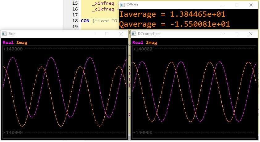
The scope window on the left shows the iq signal with a bad dose of dc offset, the window on the right shows the signal having been cleaned up.
For the upcoming FFT convolution filter I'm working on, I've made the array size of the signals etc. a parameter of the methods, rather than a constant. Here's the latest version of the library with some test programs