

How am I supposed to use COGINIT in SPIN2 to control multiple cogs in parallel?
 bernice5555
Posts: 24
bernice5555
Posts: 24
************Hello,
I am new to Spin2 and am having enormous difficulty. I am trying to use COGINIT **to turn on different LEDs in each cog, but I can't seem to get it to work. If anyone has the answer to my question, it would be a huge help.
Currently, my code looks like this:
**CON
_clkfreq = 200_000_000
****VAR****
long stack[8*32]
long cogida[8]
PUB main() | i
repeat i from 0 to 7
cogida[i] := coginit(i, @blink, @stack[i*32])
waitms(200)
repeat i from 0 to 7
if cogida[i] < 0
debug("coginit failed for cog", i, " : ", cogida[i], "\n")
repeat
waitms(1000)
PUB blink(pAddr) | mypin
mypin := 56 + cogid() 'LEDs 56 à 63
dirb[mypin] := 1
repeat
pintoggle(mypin)
waitms(300)
ooh and i work on P2X8C4M
Comments
Please format code inside ``` codeblocks so we can easily see indentation.
You have a couple of problems.
mainruns in cog 0, but the first thing it does is restart itself with your blink function, so nothing else inmainruns. Perhaps makemainonly start cogs 1-7 and then call blink itself.Do you need to allocate cog numbers yourself when you can make coginit just use the next free one? Sorry, I'm on my phone and forget the constant you need to pass coginit to make it do this, but it's in the documentation.
You're going to have a bad time trying to flash LEDs on pins 56-63, since they're already used for programming. The biggest symptom you'll probably see is that it interferes with debug output.
For launching Spin2 cogs, you should be using
cogspin(infact, I don't think@blinkwith blink being a PUB/PRI function is even valid syntax??).coginitis for launching ASM code only (this changed from Spin1!)Then why are you starting with something so obtuse? Learn the basics first, and if you want to prove to yourself that you can run the same code in multiple cogs, do it with two cogs to start with, and do make your code obvious. I copied your code from the forums and it doesn't run -- and it's not worth taking the time to fix. My version of a multi-cog blinker is easier to understand and more flexible than what you're attempting.
When in doubt, keep it simple.
var { globals } long cid0 ' cog for first blinker long stack0[32] ' stack for first blinker long cid1 ' cog for second blinker long stack1[32] ' stack for second blinker pub main() | i, byte cogsused cid0 := cogspin(newcog, blinker(LED1 , 50, 50), @stack0) ' fast blink on P56 cid1 := cogspin(newcog, blinker(LED2, 700, 300), @stack1) ' slow blink on P57 repeat i from 0 to 7 ' scan all cogs cogsused.[i] := cogchk(i) ' mark if in use debug("Blinkers using cogs ", udec_(cid0), " and ", udec_(cid1)) debug("Cogs in use: ", ubin_byte_(cogsused)) repeat ' forever pri blinker(pin, mson, msoff) ' launch with cogspin repeat pinhigh(pin) waitms(mson) pinlow(pin) waitms(msoff)Before deleting the file I looked one more time
This works
PUB main() | i

  repeat i from 1 to 5
    cogida[i] := cogspin(i, blink(), @stack[i*32])
    if cogida[i] < 0
      debug("cogspin failed for cog", i, " : ", cogida[i], "\n")
    waitms(200)

  repeat
    waitms(1000)

PUB blink() | mypin

  mypin := 56 + cogid() 'LEDs 57 à 61
  repeat
    pintoggle(mypin)
    waitms(300)
Note that pintoggle sets the direction bit for the pin so you don't need to do it manually. With Spin2's pin control commands there is almost no reason to deal with the direction bits directly.
For fun a quad version that uses cogspin and coginit.
Thank you very much for all your advice.
I was trying to learn quickly because I was asked to learn this program for a project, and since I didn't have a suitable trainer to teach me, I just dove right in.
I will try all your advice.
Does anyone know what steps I need to take to better understand this language? My first assignment is to use it with sensors to make acquisitions with the I2C bus using a cog for a sensor (assuming there will be four sensors).
Thanks.
I'd recommend checking out the OBEX (see link at top of screen).
Maybe you can find something close to what you need there to start with...
Also, good to find the "i2c scanner" if planning to work with I2C stuff...
The Spin2 language is documented here, but without a lot of examples.
-- https://docs.google.com/document/d/16qVkmA6Co5fUNKJHF6pBfGfDupuRwDtf-wyieh_fbqw/edit
Spin is pretty simple, and you can learn the basics in a day. That said, coordinating multiple cogs (that are not automatically launched by objects like serial, etc.) can be tricky and you have to be mindful.
Are you thinking that you need one cog per sensor? Unless there is a very compelling reason, I wouldn't do this.
IMO, it might be better to use a simple scheduling/timing mechanism to read the sensors. A method I frequently use is check an offset between the current system milliseconds and some desired target. If you come from a Schmarschmino background you've probably seen the use of the millis() function to make code look like it's doing multiple things at the same time. In the P2 that feature is called getms(), and it does exactly the same thing: it provides the number of milliseconds since the last reboot.
The attached demo uses this feature to flash four LEDs at different rates, all in one cog. By adding a state variable to one of the LEDs you can have asymmetric flashing (versus simple toggle). The key to this is to keep your code in each do_process() method short.
Long term, you can explore the P2's cooperative multitasking features in Spin. It's new, so there's not a lot of good examples. Try the getms() version first.
The Silicon Doc converted to HTML - https://p2docs.github.io/mirror/p2silicon.html
EDIT: Sorry, the Spin2 manual isn't converted to HTML but Google does offer PDF conversion within its bloat-fest, which works not bad. You'll have to do that yourself, it's too big a file to attach here.
Yes, that is an instruction.
Each sensor has its own I2C bus, so there is no need to worry about addresses.
For example, sensor 1 is connected to P16e and P17, while sensor 2 is connected to P18 and P19.
However, my equipment is a bit limited at the moment, so I am using a clock that is common to both sensors.
I've already created a database, but I feel like the logic I'm using is wrong.
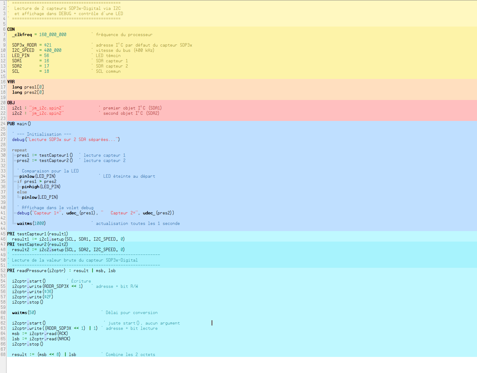
`' ============================================
' Lecture de 2 capteurs SDP3x-Digital via I2C
' et affichage dans DEBUG + contrôle d'une LED
' ============================================
CON
_clkfreq = 160_000_000 ' fréquence du processeur
SDP3x_ADDR = $21 ' adresse I²C par défaut du capteur SDP3x
I2C_SPEED = 400_000 ' vitesse du bus (400 kHz)
LED_PIN = 56 ' LED témoin
SDA1 = 16 ' SDA sensor 1
SDA2 = 17 ' SDA sensor 2
SCL = 18 ' SCL commun
VAR
long pres1[0]
long pres2[0]
OBJ
i2c1 : "jm_i2c.spin2" ' first objet I²C (SDA1)
i2c2 : "jm_i2c.spin2" ' second objet I²C (SDA2)
PUB main()
' --- Initialisation ---
debug("Lecture SDP3x sur 2 SDA séparées...")
repeat
pres1 := testCapteur1() ' lecture capteur 1
pres2 := testCapteur2() ' lecture capteur 2
' Comparaison pour la LED
 pinlow(LED_PIN)                 ' LED éteinte au départ
if pres1 > pres2
  pinhigh(LED_PIN)
else
  pinlow(LED_PIN)

' Affichage dans le volet debug
debug("Capteur 1=", udec_(pres1), "   Capteur 2=", udec_(pres2))

waitms(1000)                  ' actualisation toutes les 1 seconde
PRI testCapteur1(result1)
result1 := i2c1.setup(SCL, SDA1, I2C_SPEED, 0)
PRI testCapteur2(result2)
result2 := i2c2.setup(SCL, SDA2, I2C_SPEED, 0)
' ------------------------------------------------------------
' Lecture de la valeur brute du capteur SDP3x-Digital
' ------------------------------------------------------------
PRI readPressure(i2cptr) : result | msb, lsb
i2cptr.start() ' Écriture
i2cptr.write(ADDR_SDP3X << 1) ' adresse + bit R/W
i2cptr.write($36)
i2cptr.write($2F)
i2cptr.stop()
waitms(50) ' Délai pour conversion
i2cptr.start() ' just start(), no argument
i2cptr.write((ADDR_SDP3X << 1) | 1) ' adresse + read bit
msb := i2cptr.read(ACK)
lsb := i2cptr.read(NACK)
i2cptr.stop()
result := (msb << 8) | lsb `
Thank you
I also use the datasheet to see what i can use.
And yes Google done the convertion.
Thanks but i don't understand what i2c scanneris used for.
It scans whole address range of an I2C bus, reporting devices found on that one bus.
Scanner is an easy way to see if the hardware connection is good…
cool
thank you for the tips
Whether using one bus or many, the I2C protocol still requires device ID as part of the transaction.
If you're going to deal with each sensor in separate cogs, sharing a pin between cogs (e.g., the SCL) will create headaches and means that you cannot access two sensors at the same time which is the only advantage of multiple cogs.
Not that you're thinking, "What would JonnyMac do?" -- but this is how I'd approach it. First, define bus pins as if you have two SCL pins, even if they're shared at the minute.
con { app io pins }

  SDA1     = 17  { IO }
  SCL1     = 18  { OX }

  SDA0     = 16  { IO }
  SCL0     = 18  { OX }
BTW... you can use up to three of those sensors on the same bus, but for $22 you need a 1.2K between ADDR and GND, and for $23 you need a 2.7K between ADDR and GND.
Now create an array of I2C objects.
Setup a few useful constants . Note that I pre-build the I2C device IDs because I don't like using expressions in method arguments.
Instantiate the I2C connections.
Note: Constants don't use the instance index.
Now you can read each sensor using one method
pub main() | pres0, pres1

  setup()

  repeat
    pres0 := read_sensor(0)
    pres1 := read_sensor(1)

    if (pres0 > pres1)
      pinhigh(LED1)
    else
      pinlow(LED1)

    waitms(1000)


pub read_sensor(n) : result

'' Read sensor 0 or 1

  if (n == 0) || (n == 1)
    i2c[n].start()
    i2c[n].write(SPD3X_WR)
    i2c[n].write($36)                                           ' $362F = differential pressure
    i2c[n].write($2F)
    i2c[n].stop()
    waitms(50)                                                  ' hold-off >= 45ms
    i2c[n].start()
    i2c[n].write(SPD3X_RD)
    result.byte[1] := i2c[n].read(ACK)
    result.byte[0] := i2c[n].read(NAK)
    i2c[n].stop()
I wonder if you're under the impression that each object uses its own cog. This is not necessarily the case. Some do, but my I2C driver doesn't.
This is an example of an I2C scanner that I wrote. It started with PST, but at Ray's suggestion I made a DEBUG Terminal version which allows colors.
Code is attached. Just set the pins you're using for your I2C bus. Not that it only supports one SCL pin and one SDA pin.
I tried your code and it did a full scan, but it detected things that weren't there. I plan to check it out and find the problem today.
Thanks for all your help. I started a few days ago with a professional request, but the more I learn, the more I think I'll use it in my personal projects.
I'll give you an update on how it's going.
update
it's because it's missing external pull-up
P2 has internal pull-ups you can use…
Should be an option in scanner code.
Pullups are a requirement of I2C, regardless of which driver you use. Many products have them built in (like the RTC/EEPROM) board used in my screencaps. You'll get better help here in the forums when you are more forthcoming with what you have and what you want to do.
PU_15K, PU_3K3, and PU_1K5 are options in my I2C object.
Hello everyone,
I’m using Jon McPhallen’s I2C scanner, which is usually reliable, but I’m having an issue: I cannot detect the addresses of my I2C devices.
Specifically:
I have two I2C buses connected, but the scanner returns “0 I2C buses.”
I’ve correctly added external pull-up resistors between SDA and Vcc, and between SCL and Vcc.
I haven’t used a specific address pin because I don’t need to differentiate multiple ports.
My hardware: P2X8C5M64P + SDP3x-Digital pressure sensor.
My goal is to read my sensors in real-time, view the data, and later store this data in the hub.
Does anyone have any idea what could be causing this issue or a solution to get the scanner to detect my devices?
Thanks in advance for your help!
You will need to set the scl and sda parameters to match the actual io pins being used.
You can only scan one bus at a time with this code…
Is the SCL pin of your device connected to pin P0 of the Propeller?
Is the SDA pin of your device connected to pin P1 of the Propeller?
I seem to remember you suggesting that you were using P18 for SCL, and P17 and P16 for SDA pins (if this is still the case you'll have to scan one bus at a time). My scanner is a tool with configuration constants so that you can match to your existing hardware. For any given system you need to set the SCL pin used, the SDA pin used, the I2C bus speed (in kHz) and the pull-up type (see jm_i2c.spin2 for pull-up constants).
It works when it's used properly. If you don't think so, please write a better program to contribute to the community. I'm always happy to learn from others.
Don't worry — I have complete confidence in your work! You have helped me out several times before.
I didn't express myself clearly. I was asking what I was doing wrong.
Thank you again. I neglected to change the pins because I wasn't paying attention.
I added SCL and SDA pins to the display because I've run into that, too -- we're all human. Are your devices being detected now?
yess it's working , thank you
i know now that my code just not working
Go slowly. Now that you can detect a device, write a simple bit of code to get some data from the device. If you proceed very slowly like this, you'll get to the end faster. Like they say in auto racing (about taking critical corners): slow in means fast out. And, yes, I take my own medicine. Today I'm working on code that is critical for a big app, but I'm working on that code outside my app.
Thank you very much for your advice and good luck with your application. Your medication seems to be working.
It was difficult at first, but I finally managed it after two more days of hard work.
I can read my sensor, and even two at the same time.
But now I'm facing another problem because I want all the tasks that a sensor has to perform in the I2C bus to be done by one cog, and a second sensor to be processed by another cog.
I thought it would be easy since I was already able to read them together in one cog, but no.
I relied heavily on the jm_i2c.spin2 object for the base that read a sensor, and now I'm still trying to achieve parallelism.
If anyone has any ideas, please let me know. Feel free to ask me questions if you don't understand something in my code.
I'll answer as best I can.
`' ==== SDP3x x2 (deux bus I²C) ====
CON
_clkfreq = 160_000_000
I2C_KHZ = 400
' Bus #0
SDA1 = 8
SCL1 = 9
' Bus #1
SDA2 = 10
SCL2 = 11
' Adresse 7-bit = $21 -> write=$42, read=$43
SPD3X_WR = $42
SPD3X_RD = $43
#0, ACK, NACK
VAR
byte rx1[9] ' trame capteur 1 : dp+crc, T+crc, scale+crc
byte rx2[9] ' trame capteur 2
long stack0[512]
long stack1[512]
long pd_raw
long t_raw
long scale
long ok0
long ok1
OBJ
i2c : "jm_i2c.spin2" ' deux instances I²C (bus 0 et bus 1)
PUB main() | cog1 , cog2
debug("Init I2C buses...")
cog1:= cogspin(1 , boom1(), @stack0)
cog2:= cogspin(2 , boom2(), @stack1)
debug("communication réussi")
debug(" ")
waitms(5000)
PRI boom1()
i2c.setup(SCL1, SDA1, I2C_KHZ, i2c.PU_EXT)
ok0 := i2c.present(SPD3X_WR)
if ok0 == 0
debug("Capteur #1 absent sur bus0 ($21).")
if ok0
soft_reset(0)
if ok0
start_measure(0)
waitms(5000)
' ---- CAPTEUR 1 ----
repeat
if ok0 and read_frame(0, @rx1)
  pd_raw := (rx1[0] << 8) | rx1[1]
  t_raw:= (rx1[3] << 8) | rx1[4]
  scale:= (rx1[6] << 8) | rx1[7]
  debug("Capteur 1: ")
  show_reading(pd_raw, t_raw, scale)
elseif ok0
  debug("S1: lecture NACK/CRC invalide")
  waitms(1000)
waitms(2000)
PRI boom2()
i2c.setup(SCL2, SDA2, I2C_KHZ, i2c.PU_EXT)
ok1 := i2c.present(SPD3X_WR)
if ok1 == 0
debug("Capteur #2 absent sur bus1 ($21).")
if ok1
soft_reset(1)
if ok1
start_measure(1)
waitms(5000)
' ---- CAPTEUR 2 ----
repeat
if ok1 and read_frame(1, @rx2)
pd_raw := (rx2[0] << 8) | rx2[1]
t_raw := (rx2[3] << 8) | rx2[4]
scale := (rx2[6] << 8) | rx2[7]
debug("Capteur 2: ")
show_reading(pd_raw, t_raw, scale)
elseif ok1
debug("S2: lecture NACK/CRC invalide")
waitms(1000)
' --- commandes périphérique ---
PRI soft_reset(n)
i2c.start()
i2c.write(SPD3X_WR) ' general call
i2c.write($00)
i2c.write($06)
i2c.stop()
debug("fait1")
waitms(10)
PRI start_measure(n)
i2c.start()
i2c.write(SPD3X_WR)
i2c.write($36)
i2c.write($15) ' continuous averaged
i2c.stop()
debug("fait2")
PRI stop_measure(n)
i2c.start()
i2c.write(SPD3X_WR)
i2c.write($3F)
i2c.write($F9) ' stop continuous
i2c.stop()
debug("fait3")
' --- lecture 9 octets + CRC ---
PRI read_frame(n, p_buf) : ok | c
i2c.start()
c := i2c.write(SPD3X_RD)
debug("n= " , udec(n), " ack=", udec(c))
if c <> ACK
i2c.stop()
return 0
debug("ACK const=", udec(i2c.ACK), " NACK const=", udec(i2c.NACK))
i2c.rd_block(p_buf, 9, NACK)
i2c.stop()
ok := crc_ok(byte[p_buf][0], byte[p_buf][1], byte[p_buf][2])
ok := ok and crc_ok(byte[p_buf][3], byte[p_buf][4], byte[p_buf][5])
ok := ok and crc_ok(byte[p_buf][6], byte[p_buf][7], byte[p_buf][8])
' --- CRC Sensirion (poly 0x31, init 0xFF) ---
PRI crc_ok(b0, b1, crc) : ok | c, i, j
c := $FF
repeat j from 0 to 1
i := (j == 0) ? b0 : b1
c ^= i
repeat 8
if (c & $80)
c := (c << 1) ^ $31
else
c := (c << 1)
c := c & $FF
ok := (c == crc)
' --- utilitaires conversion/affichage ---
PRI s16(x) : y
y := x
if (y & $8000)
y -= 65536
' Affiche en entiers : mPa et dixièmes de °C
PRI show_reading(dp_raw, ti_raw, scali) | pd_s, t_s, p_Pa, t_celcius
pd_s := s16(dp_raw)
t_s := s16(ti_raw)
p_Pa := (pd_s ) / scali ' milli-Pascal
t_celcius := (t_s ) / 200 ' dixièmes de °C
debug("brute: pd_raw=", sdec_(pd_s), " T_raw=", sdec_(t_s), " scale=", udec_(scali))
debug("physique: ΔP[Pa]=", sdec_(p_Pa), " T[0.1°C]=", sdec_(t_celcius))`
You're welcome. Yesterday I started from scratch and took a different approach to my problem -- as I have said to my friend John Huffman (@jonyjib), sometimes it's best to burn it down and start over. I found the issue, and updated a library so I don't encounter that issue again.
If I may, you seem to have trouble posting formatted code; I suspect this may be caused by characters in your code from what I'm guessing is a European keyboard. It may be better to simply attach the code that you'd like reviewed.
Now.... in my opinion you're still starting out too big. Until you can reliably communicate with your device there is no point building a multi-cog system (which I doubt you actually need) . I don't have that part and am not willing to shell our $32 to buy one, but as a "while I'm having a coffee" exercise I wrote a program for you like I would for myself if I were dealing with that sensor. I put in my own CRC calculator because I missed that you had included one in your code. Both versions work, though mine is about 11x faster because it uses inline assembly versus pure Spin2.
Again: Just get one thing working before adding a bunch to your code -- it's a lot less to troubleshoot. As I said earlier, I started over with a very simple program yesterday and finally found my problem (which was an assumption about how one of my own libraries worked that was incorrect).
Found this comment in the datasheet:
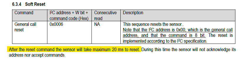
pub soft_reset()

  i2c.start()
  i2c.write(SPD3X_WR)
  i2c.write($00)
  i2c.write($06)
  i2c.stop()

  waitms(25)

  debug("Device reset")
You have a method that converts signed 16-bit to a signed long:
pri s16(x) : y

  y := x
  if (y & $8000)
    y -= 65536
You can do it like this with Spin2:
or
Note: This counts on you copying two bytes from the input buffer to bytes 1 and 0 of a long (x). No need to wrap this code in a method; that just adds overhead.