Just for fun on a Saturday. The original version takes 7568 ticks, this version -- which is a near direct translation -- takes only 784 ticks (about 9.65x faster). I'm not great at assembly, so I really like that the P2 has inline assembly which makes life easy when it comes to PASM experiments.
pub crc_ok(b0, b1, crc) : ok | c, b, i

  org
                        mov       c, #$FF                       ' set initial crc
                        mov       b, b0                         ' 1st byte
                        call      #.do_crc
                        mov       b, b1                         ' 2nd byte
                        call      #.do_crc
                        cmp       c, crc                wcz     ' compare calc to crc
        if_e            neg       ok, #1                        ' set ok true if match
                        jmp       #.done                        ' exit

.do_crc                 xor       c, b
                        mov       i, #8
.loop                   testb     c, #7                 wc
                        shl       c, #1
        if_c            xor       c, #$31
                        djnz      i, #.loop
        _ret_           and       c, #$FF
.done
  end
@JonnyMac said:
You're welcome. Yesterday I started from scratch and took a different approach to my problem -- as I have said to my friend John Huffman (@jonyjib), sometimes it's best to burn it down and start over. I found the issue, and updated a library so I don't encounter that issue again.
If I may, you seem to have trouble posting formatted code; I suspect this may be caused by characters in your code from what I'm guessing is a European keyboard. It may be better to simply attach the code that you'd like reviewed.
I was unlucky, so I only visited the site when it wasn't working, hence my late reply.
Yes, I do use a European keyboard, so I'm having trouble displaying my code properly.
I'll take a look at what you suggest and get back to you. Thanks again for all your efforts.
I have a quick question: I feel like the PASM2 language is so much more complicated than the simple but more useful Spin2.
Not having had access to the forum for a while, I managed to cobble together a little something that successfully read and displayed my sensors in Spin2, but without using cogspin as I wanted to, in order to get the basics down.
I managed to acquire a sensor in Spin2, and when I see Jon's suggestion, I realize that I really racked my brains for nothing to come up with something complex .
But as I mentioned earlier, I have to write and read a different cog from Cog0 on each sensor
so I'm just trying to read a sensor with cog1, but it's not working at all, even though I'm not making any major changes to my current code.
@bernice5555 said:
Not having had access to the forum for a while, I managed to cobble together a little something that successfully read and displayed my sensors in Spin2, but without using cogspin as I wanted to, in order to get the basics down.
I managed to acquire a sensor in Spin2, and when I see Jon's suggestion, I realize that I really racked my brains for nothing to come up with something complex .
But as I mentioned earlier, I have to write and read a different cog from Cog0 on each sensor
so I'm just trying to read a sensor with cog1, but it's not working at all, even though I'm not making any major changes to my current code.
Following my message, I am adding my code that is not working.
I have a quick question: I feel like the PASM2 language is so much more complicated than the simple but more useful Spin2.
PASM -- because it's what actually runs the machine -- will be a little more complicated than any high-level language (Spin, C, BASIC, etc.), but as programmer, Chip Gracey has made PASM very approachable, especially in small chunks. One of my favorite features of the P2 is the ability to run small PASM segments inside Spin2 methods. This can be really helpful and sometimes save the use of a cog. I'll give you a real-world example: in my current work project (a laser tag game piece) we use 45 WS2812 LEDs). The WS2812 protocol has very strict timing which cannot be accomplished in Spin, it must be one in PASM. In my project, the LEDs are not very dynamic so I wrote a cogless driver -- this updates the LEDs when needed and saves a precious cog.
A question you should ask is... "Do I really need a cog for this process?" Based on what you've shared thus far, I don't think you need to read your sensors in separate cogs. And on that, look at the I2C object of mine that you're using: it uses inline PASM to ensure the bit timing specified in the setup() method is what you get.
But as I mentioned earlier, I have to write and read a different cog from Cog0 on each sensor
I have a quick question: I feel like the PASM2 language is so much more complicated than the simple but more useful Spin2.
PASM -- because it's what actually runs the machine -- will be a little more complicated than any high-level language (Spin, C, BASIC, etc.), but as programmer, Chip Gracey has made PASM very approachable, especially in small chunks. One of my favorite features of the P2 is the ability to run small PASM segments inside Spin2 methods. This can be really helpful and sometimes save the use of a cog. I'll give you a real-world example: in my current work project (a laser tag game piece) we use 45 WS2812 LEDs). The WS2812 protocol has very strict timing which cannot be accomplished in Spin, it must be one in PASM. In my project, the LEDs are not very dynamic so I wrote a cogless driver -- this updates the LEDs when needed and saves a precious cog.
A question you should ask is... "Do I really need a cog for this process?" Based on what you've shared thus far, I don't think you need to read your sensors in separate cogs. And on that, look at the I2C object of mine that you're using: it uses inline PASM to ensure the bit timing specified in the setup() method is what you get.
Hi,
Thank you for answering my question. To answer your question about why I want to run my sensors in different cogs, it is because I need to make them independent of each other, and they need to be synchronized in terms of startup, data, and the execution of other related tasks, which is a specific requirement in my specifications.
Okay, but you can do that without consuming separate cogs. I think I showed you how to setup a timer object to access devices on a schedule.
It took a few minutes, some tea, then and upgrade to coffee to get going this morning (stayed up too late watching the Dodgers game [my grandfather helped build Dodgers Stadium]), but I finally remembered an old project and figured out why you're having difficulty with your sensors in separate cogs.
One of the tricky aspects of multi-cog projects is IO. Yes, there are only 64 pins, but each cog has its own set of dirs, outs, and ins registers -- and you cannot access IO under control in one cog directly from another cog. I2C is an IO process, and my I2C driver uses inline assembly, meaning it runs in the interpreter that started it. What this boils down to is that you cannot access I2C functions from your sensor cogs that were started in your main cog. I ran into this -- also with I2C -- when helping my friend John (owner of JonyJib) when we ported one of his P1 products to the P2.
No worries; you can -- if you absolutely need to -- run those sensors in separate cogs. The key is that all of your I2C access for a sensor MUST be done in the cog where the I2C is instantiated.
Talk is cheap, so I did a small demo to prove my point -- and retrain myself for the future. I don't have your sensors, but I do have an RTC object that uses my i2C object. This device also has temperature measurement so I tossed that in. What you'll see is the background cog starts the RTC and does the I2C access from that cog. The great thing about Spin cogs that are launched inside our application is that they have access to the application's global variables. You'll see that I have time registers and the temperature as global variables, and the background cog reads the RTC into these globals.
The Propeller is simple, but not always easy. This is a very subtle issue you've run into; hopefully my explanation make sense. Here's what the demo output looks like
No, it's not 81.5 degrees F (27.5C) at my desk -- that temperature happened when I set a big cup of hot coffee next to the RTC module!
Whoops... found a gotcha right after posting. Corrected. Make sure the version your running is marked VERSION = 0_1_1.
Suppose it could be possible to create a modified version of the I2C driver that drove many I2C ports simultaneously. Perhaps just using "addpins" and some changes to the read and write routines...
But, I2C is so slow compared to P2 code, that I seriously doubt any special things are needed for any project.
...it is because I need to make them independent of each other, and they need to be synchronized in terms of startup, data, and the execution of other related tasks, which is a specific requirement in my specifications.
Unless you're doing everything I2C-related in the background cog -- which isn't indicated by your code -- you're just making your life more difficult. In practical terms, reading your sensor using 400kHz I2C means you're getting data back in well under a half a millisecond. With buffer validation and data conversion, you're still under a millisecond to process a sensor. So... if you're only reading a sensor every second or so, a millisecond isn't doing your system any harm. I've written hundreds of P1 and P2 programs and created commercial products with both; please trust me on this -- especially since you're so new to the Propeller hardware.
which is a specific requirement in my specifications.
What are those specifications? Maybe you don't need extra cogs, just direction in how to so what you want to do.
A feature that I'm using in my current laser-tag game project is pollct(). This lets you check the system timer to see if it has reached or exceed a specific value. In my case I have to animate the motion of 15 pixels while also checking for IR input and RF input. Using pollct() is a non-blocking way to get pixel-to-pixel timing accurate while my system has to handle critical processes like IR and RF input.
I attached a simple pollct() demo to show you how easy it is to implement. By using a target variable for each process, you can sync to other system events.
Thanks for the advice.
Actually, I agree that using one cog per sensor is unnecessary, because I have long been able to read them in the first cog and the measurements are taken almost instantly (which almost meets my supervisor's requirements).
However, to ensure reliability (to be sure that everything is done at the same time), I am required to do them in each cog (my supervisor is also looking into this with me, but we haven't found a solution yet; we are working on it).
I find your work impressive and very practical.
I tried your jm_i2c_in_cog_demo and jm_pollct_demo code, and the measurements are working perfectly. I think it will be useful to me (this time I remembered to change the pin numbers).
Anyway, I just wanted to let you know that I find your suggestions very economical and practical, and that's what I would have set out to do, but I'm being asked to do more (luckily I don't have a deadline). But it's hard to concentrate when you know you don't have the skills for what's being asked of you, and it's been almost a week since I started looking for the same thing with restrictions like not using PASM2 and separating the cogs.
PS: I'll let him take a look at what I have for reading the two sensors without using multiple cogs (it's a bit all over the place, but it works well).
@Rayman said:
Suppose it could be possible to create a modified version of the I2C driver that drove many I2C ports simultaneously. Perhaps just using "addpins" and some changes to the read and write routines...
But, I2C is so slow compared to P2 code, that I seriously doubt any special things are needed for any project.
Hi,
I'm afraid that when using addpins, the system gets confused between the stacks and the data to be stored,
unless I'm mistaken. Could you explain your idea in more detail? From what I can see in the documentation, addpin could break the I2C buses.
..(which almost meets my supervisor's requirements)...
Is this a school project? I find it interesting that you would be constrained to NOT using any PASM. The Spin interpreter is simply a collection of PASM routines (that are tightly woven together).
If you are restricted to Spin, you might as well take advantage:
PRI s16(x) : y
  y := x
  if (y & $8000)
    y -= 65536
can be replaced with
x signx= 15
Thank you for the advice on conversion. I used it and didn't notice any change.
To answer your question, no, it's not a school project. To enrich my educational experience, I decided to do a work-study program, and this is my first assignment. After much searching, I discovered the forum, which has been a huge help.
The work-study program explains all the restrictions I have.
There shouldn't be any change except in speed (which is too fast for humans to perceive). Just for the record, I'm not in the habit of posting code that I haven't tested myself. 😁
At some point, speed will become important. Luckily, the P2 lets us measure the speed of code without any special hardware. This is something I do all the time:
pub main() | t
t := getct()
' test code goes here
t := getct()-t-48
debug(udec(t))
repeat
' forever
This will measure the number of system ticks between the two t := lines. The reason for the - 48 in the second of these lines is that removes the interpreter overhead for those two lines. I've attached a demo to that may help.
If anything I say sticks, please keep this: Allow yourself to experiment.
If one did want to have 8 identical i2c busses all with the same slave device and wanted them to be simultaneous , could hack the driver to do it (probably).
Use say pins 0..7 for the SDAs and 8..15 for the SCLs. Add “addpins 7” to the pin definitions.
Then rework the read code to get the input bits sorted out.
There shouldn't be any change except in speed (which is too fast for humans to perceive). Just for the record, I'm not in the habit of posting code that I haven't tested myself. 😁
At some point, speed will become important. Luckily, the P2 lets us measure the speed of code without any special hardware. This is something I do all the time:
pub main() | t
t := getct()
' test code goes here
t := getct()-t-48
debug(udec(t))
repeat
' forever
This will measure the number of system ticks between the two t := lines. The reason for the - 48 in the second of these lines is that removes the interpreter overhead for those two lines. I've attached a demo to that may help.
If anything I say sticks, please keep this: Allow yourself to experiment.
I tried it, but I must admit I didn't understand the result.
If one did want to have 8 identical i2c busses all with the same slave device and wanted them to be simultaneous , could hack the driver to do it (probably).
Use say pins 0..7 for the SDAs and 8..15 for the SCLs. Add “addpins 7” to the pin definitions.
Then rework the read code to get the input bits sorted out.
Probably a complete waste of time though…
Oh, I see, I see.
That sounds interesting. I'll let you know what I think once I've tried it.
I tried it, but I must admit I didn't understand the result.
What you're seeing in the image you posted is the second process is almost 10x faster than the first (it's taking fewer system ticks).
Let me explain in human terms.
You look at the clock and note the time
You do a task
You look at the clock again
The difference between the second time you looked at the clock and the first time you looked is the time consumed by your task.
Sometimes being verbose is best to getting started -- hopefully, this example makes what's happening clearer.
pub main() | tStart, tStop, tDelta
tStart := getct()
' test code here
tStop := getct()
tDelta := tStop - tStart - 40
debug(udec(tDelta))
repeat
' wait here
You'll see that the correction offset is a little smaller in this version because the second line that uses getct() in this version is simpler and takes less time. You should see this:
Sometimes we'll want a real-world measurement. In those cases I will do something like this:
tDelta := (tDelta + US_001/2) / US_001
This line converts system ticks to microseconds -- with rounding up.
If you look in my programs I have a timing section with useful constants that are set based on the specified clock frequency.
con { timing }
CLK_FREQ = 200_000_000 ' system freq as a constant
MS_001 = CLK_FREQ / 1_000 ' ticks in 1ms
US_001 = CLK_FREQ / 1_000_000 ' ticks in 1us
_clkfreq = CLK_FREQ ' set system clock
The US_001 and MS_001 constants are useful in Spin because built-in functions like waitct() and pollct() work in system ticks. There will be times when you want to run a process at a very specific rate; this is where waitct() is really helpful. With waitct() we can create what is called a synchronized loop.
pub main() | t
t := getct() ' sync loop timer
repeat
' loop code here
waitct(t += CLK_FREQ) ' run loop every second
In this case, the code inside the loop will run exactly every second -- so long as the code between repeat and waitct() takes less than a second. In your case, maybe you want to read the sensors every second; your main loop might look like this:
pub main() | t
t := getct()
repeat
read_sensor_1()
read_sensor_2()
process_sensors()
waitct(t += CLK_FREQ)
The loop above runs exactly one time per second. This loop does not:
Why? Because the loop is doing four different processes that take time -- including the 1-second delay. Now, could tune that delay but this is only useful if there is no variability in your other processes. This is where waitct() helps us; so long as we don't overrun the waitct() target, the contents of the loop will run a fixed rate, even when there is variability in the individual processes.
You may notice that I like to keep my main loop small and clean. As you're developing your project, look for ways to have small, atomic methods that can be called from a simple main loop like this.
I put a lot of emphasis on the value of waitct() because it is important in many processes. For example, I write code for my friend John Huffman (of JonyJib) who makes camera platform controls that communicate with the master over RS-485 or XBee radio. We want to send updates from the master to the control head at a rate of 30 frames / second. In that case, we have a constant like this:
FPS_TICKS = CLK_FREQ / 30
This is the modifier for the waitct() target and our messages are sent (and responses received) exactly 30x per second. This gives the operator smooth control.
It can take a minute to wrap one's head around waitct(). In a post above I encouraged you to experiment. Here's a simple experiment you can play with to understand.
Keys to remember:
loop needs a timer variable (initialized with getct())
loop code can have variability -- so long as it doesn't exceed the specified loop time
In this little demo we're setting the loop to run every second (CLK_FREQ ticks). The loop timing is indicated with a toggling LED. To simulate a variable process we create a randomized delay that runs from 250 to 500 milliseconds. Note that no matter what the delay does, the LED toggles every second. Once this sinks in you're going to be very happy -- especially if you're doing any kind of industrial process with the Propeller.
I'm a very visual person so one of my favorite pieces of test gear is a logic analyzer. I updated the experiment code to flash one LED with the random delay.


Comments
Just for fun on a Saturday. The original version takes 7568 ticks, this version -- which is a near direct translation -- takes only 784 ticks (about 9.65x faster). I'm not great at assembly, so I really like that the P2 has inline assembly which makes life easy when it comes to PASM experiments.
pub crc_ok(b0, b1, crc) : ok | c, b, i org mov c, #$FF ' set initial crc mov b, b0 ' 1st byte call #.do_crc mov b, b1 ' 2nd byte call #.do_crc cmp c, crc wcz ' compare calc to crc if_e neg ok, #1 ' set ok true if match jmp #.done ' exit .do_crc xor c, b mov i, #8 .loop testb c, #7 wc shl c, #1 if_c xor c, #$31 djnz i, #.loop _ret_ and c, #$FF .done endI was unlucky, so I only visited the site when it wasn't working, hence my late reply.
Yes, I do use a European keyboard, so I'm having trouble displaying my code properly.
I'll take a look at what you suggest and get back to you. Thanks again for all your efforts.
I have a quick question: I feel like the PASM2 language is so much more complicated than the simple but more useful Spin2.
Not having had access to the forum for a while, I managed to cobble together a little something that successfully read and displayed my sensors in Spin2, but without using cogspin as I wanted to, in order to get the basics down.
 .
.
I managed to acquire a sensor in Spin2, and when I see Jon's suggestion, I realize that I really racked my brains for nothing to come up with something complex
But as I mentioned earlier, I have to write and read a different cog from Cog0 on each sensor
so I'm just trying to read a sensor with cog1, but it's not working at all, even though I'm not making any major changes to my current code.
Following my message, I am adding my code that is not working.
PASM -- because it's what actually runs the machine -- will be a little more complicated than any high-level language (Spin, C, BASIC, etc.), but as programmer, Chip Gracey has made PASM very approachable, especially in small chunks. One of my favorite features of the P2 is the ability to run small PASM segments inside Spin2 methods. This can be really helpful and sometimes save the use of a cog. I'll give you a real-world example: in my current work project (a laser tag game piece) we use 45 WS2812 LEDs). The WS2812 protocol has very strict timing which cannot be accomplished in Spin, it must be one in PASM. In my project, the LEDs are not very dynamic so I wrote a cogless driver -- this updates the LEDs when needed and saves a precious cog.
A question you should ask is... "Do I really need a cog for this process?" Based on what you've shared thus far, I don't think you need to read your sensors in separate cogs. And on that, look at the I2C object of mine that you're using: it uses inline PASM to ensure the bit timing specified in the setup() method is what you get.
Why
Hi,
Thank you for answering my question. To answer your question about why I want to run my sensors in different cogs, it is because I need to make them independent of each other, and they need to be synchronized in terms of startup, data, and the execution of other related tasks, which is a specific requirement in my specifications.
Okay, but you can do that without consuming separate cogs. I think I showed you how to setup a timer object to access devices on a schedule.
It took a few minutes, some tea, then and upgrade to coffee to get going this morning (stayed up too late watching the Dodgers game [my grandfather helped build Dodgers Stadium]), but I finally remembered an old project and figured out why you're having difficulty with your sensors in separate cogs.
One of the tricky aspects of multi-cog projects is IO. Yes, there are only 64 pins, but each cog has its own set of dirs, outs, and ins registers -- and you cannot access IO under control in one cog directly from another cog. I2C is an IO process, and my I2C driver uses inline assembly, meaning it runs in the interpreter that started it. What this boils down to is that you cannot access I2C functions from your sensor cogs that were started in your main cog. I ran into this -- also with I2C -- when helping my friend John (owner of JonyJib) when we ported one of his P1 products to the P2.
No worries; you can -- if you absolutely need to -- run those sensors in separate cogs. The key is that all of your I2C access for a sensor MUST be done in the cog where the I2C is instantiated.
Talk is cheap, so I did a small demo to prove my point -- and retrain myself for the future. I don't have your sensors, but I do have an RTC object that uses my i2C object. This device also has temperature measurement so I tossed that in. What you'll see is the background cog starts the RTC and does the I2C access from that cog. The great thing about Spin cogs that are launched inside our application is that they have access to the application's global variables. You'll see that I have time registers and the temperature as global variables, and the background cog reads the RTC into these globals.
The Propeller is simple, but not always easy. This is a very subtle issue you've run into; hopefully my explanation make sense. Here's what the demo output looks like
No, it's not 81.5 degrees F (27.5C) at my desk -- that temperature happened when I set a big cup of hot coffee next to the RTC module!
Whoops... found a gotcha right after posting. Corrected. Make sure the version your running is marked VERSION = 0_1_1.
Suppose it could be possible to create a modified version of the I2C driver that drove many I2C ports simultaneously. Perhaps just using "addpins" and some changes to the read and write routines...
But, I2C is so slow compared to P2 code, that I seriously doubt any special things are needed for any project.
Unless you're doing everything I2C-related in the background cog -- which isn't indicated by your code -- you're just making your life more difficult. In practical terms, reading your sensor using 400kHz I2C means you're getting data back in well under a half a millisecond. With buffer validation and data conversion, you're still under a millisecond to process a sensor. So... if you're only reading a sensor every second or so, a millisecond isn't doing your system any harm. I've written hundreds of P1 and P2 programs and created commercial products with both; please trust me on this -- especially since you're so new to the Propeller hardware.
What are those specifications? Maybe you don't need extra cogs, just direction in how to so what you want to do.
A feature that I'm using in my current laser-tag game project is pollct(). This lets you check the system timer to see if it has reached or exceed a specific value. In my case I have to animate the motion of 15 pixels while also checking for IR input and RF input. Using pollct() is a non-blocking way to get pixel-to-pixel timing accurate while my system has to handle critical processes like IR and RF input.
I attached a simple pollct() demo to show you how easy it is to implement. By using a target variable for each process, you can sync to other system events.
Thanks for the advice.
Actually, I agree that using one cog per sensor is unnecessary, because I have long been able to read them in the first cog and the measurements are taken almost instantly (which almost meets my supervisor's requirements).
However, to ensure reliability (to be sure that everything is done at the same time), I am required to do them in each cog (my supervisor is also looking into this with me, but we haven't found a solution yet; we are working on it).
I find your work impressive and very practical.
I tried your jm_i2c_in_cog_demo and jm_pollct_demo code, and the measurements are working perfectly. I think it will be useful to me (this time I remembered to change the pin numbers).
Anyway, I just wanted to let you know that I find your suggestions very economical and practical, and that's what I would have set out to do, but I'm being asked to do more (luckily I don't have a deadline). But it's hard to concentrate when you know you don't have the skills for what's being asked of you, and it's been almost a week since I started looking for the same thing with restrictions like not using PASM2 and separating the cogs.
PS: I'll let him take a look at what I have for reading the two sensors without using multiple cogs (it's a bit all over the place, but it works well).
Hi,
I'm afraid that when using addpins, the system gets confused between the stacks and the data to be stored,
unless I'm mistaken. Could you explain your idea in more detail? From what I can see in the documentation, addpin could break the I2C buses.
Is this a school project? I find it interesting that you would be constrained to NOT using any PASM. The Spin interpreter is simply a collection of PASM routines (that are tightly woven together).
If you are restricted to Spin, you might as well take advantage:
PRI s16(x) : y
  y := x
  if (y & $8000)
    y -= 65536
can be replaced with
Thank you for the advice on conversion. I used it and didn't notice any change.
To answer your question, no, it's not a school project. To enrich my educational experience, I decided to do a work-study program, and this is my first assignment. After much searching, I discovered the forum, which has been a huge help.
The work-study program explains all the restrictions I have.
There shouldn't be any change except in speed (which is too fast for humans to perceive). Just for the record, I'm not in the habit of posting code that I haven't tested myself. 😁
At some point, speed will become important. Luckily, the P2 lets us measure the speed of code without any special hardware. This is something I do all the time:
This will measure the number of system ticks between the two t := lines. The reason for the - 48 in the second of these lines is that removes the interpreter overhead for those two lines. I've attached a demo to that may help.
If anything I say sticks, please keep this: Allow yourself to experiment.
If one did want to have 8 identical i2c busses all with the same slave device and wanted them to be simultaneous , could hack the driver to do it (probably).
Use say pins 0..7 for the SDAs and 8..15 for the SCLs. Add “addpins 7” to the pin definitions.
Then rework the read code to get the input bits sorted out.
Probably a complete waste of time though…
Agreed -- especially if you want to handle clock stretching.
I tried it, but I must admit I didn't understand the result.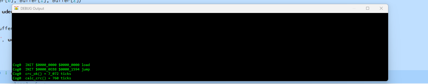
Oh, I see, I see.
That sounds interesting. I'll let you know what I think once I've tried it.
What you're seeing in the image you posted is the second process is almost 10x faster than the first (it's taking fewer system ticks).
Let me explain in human terms.
The difference between the second time you looked at the clock and the first time you looked is the time consumed by your task.
Sometimes being verbose is best to getting started -- hopefully, this example makes what's happening clearer.
You'll see that the correction offset is a little smaller in this version because the second line that uses getct() in this version is simpler and takes less time. You should see this:
Sometimes we'll want a real-world measurement. In those cases I will do something like this:
This line converts system ticks to microseconds -- with rounding up.
If you look in my programs I have a timing section with useful constants that are set based on the specified clock frequency.
con { timing }

  CLK_FREQ = 200_000_000                                        ' system freq as a constant
  MS_001   = CLK_FREQ / 1_000                                   ' ticks in 1ms
  US_001   = CLK_FREQ / 1_000_000                               ' ticks in 1us

  _clkfreq = CLK_FREQ                                           ' set system clock
The US_001 and MS_001 constants are useful in Spin because built-in functions like waitct() and pollct() work in system ticks. There will be times when you want to run a process at a very specific rate; this is where waitct() is really helpful. With waitct() we can create what is called a synchronized loop.
pub main() | t

  t := getct()                                                  ' sync loop timer

  repeat

    ' loop code here

    waitct(t += CLK_FREQ)                                       ' run loop every second
In this case, the code inside the loop will run exactly every second -- so long as the code between repeat and waitct() takes less than a second. In your case, maybe you want to read the sensors every second; your main loop might look like this:
pub main() | t

  t := getct()

  repeat
    read_sensor_1()
    read_sensor_2()
    process_sensors()
    waitct(t += CLK_FREQ)
The loop above runs exactly one time per second. This loop does not:
pub main()

  repeat
    read_sensor_1()
    read_sensor_2()
    process_sensors()
    waitms(1000)
Why? Because the loop is doing four different processes that take time -- including the 1-second delay. Now, could tune that delay but this is only useful if there is no variability in your other processes. This is where waitct() helps us; so long as we don't overrun the waitct() target, the contents of the loop will run a fixed rate, even when there is variability in the individual processes.
You may notice that I like to keep my main loop small and clean. As you're developing your project, look for ways to have small, atomic methods that can be called from a simple main loop like this.
I put a lot of emphasis on the value of waitct() because it is important in many processes. For example, I write code for my friend John Huffman (of JonyJib) who makes camera platform controls that communicate with the master over RS-485 or XBee radio. We want to send updates from the master to the control head at a rate of 30 frames / second. In that case, we have a constant like this:
This is the modifier for the waitct() target and our messages are sent (and responses received) exactly 30x per second. This gives the operator smooth control.
It can take a minute to wrap one's head around waitct(). In a post above I encouraged you to experiment. Here's a simple experiment you can play with to understand.
Keys to remember:
In this little demo we're setting the loop to run every second (CLK_FREQ ticks). The loop timing is indicated with a toggling LED. To simulate a variable process we create a randomized delay that runs from 250 to 500 milliseconds. Note that no matter what the delay does, the LED toggles every second. Once this sinks in you're going to be very happy -- especially if you're doing any kind of industrial process with the Propeller.
pub main() | t, delay t := getct() repeat delay := getrnd() +// 251 + 250 ' randomize from 250..500 debug(udec(delay)) waitms(delay) waitct(t += CLK_FREQ) pintoggle(56)I'm a very visual person so one of my favorite pieces of test gear is a logic analyzer. I updated the experiment code to flash one LED with the random delay.
pub main() | t, delay

  t := getct()

  repeat
    delay := getrnd() +// 801 + 100                     ' randomize from 100..900
    debug(udec(delay))
    pinhigh(57)
    waitms(delay)
    pinlow(57)
    waitct(t += CLK_FREQ)
    pintoggle(56)
Connecting the L/A to those pins allows the process to be analyzed.
Note how the top trace toggles every second no matter how long the second input is active. This is waitct() in operation.