Sorry ,another bad on my part, I should have sent EQ@-B instead . please change the tx and rx pins to rx =5 and tx=6 Also check the download on the schematic it should have a "copy" at the end ,if not then download again. Thanks
@bbrien said:
Sorry ,another bad on my part, I should have sent EQ@-B instead . please change the tx and rx pins to rx =5 and tx=6 Also check the download on the schematic it should have a "copy" at the end ,if not then download again. Thanks
Oh, @bbrien,
so once again no thank you but once again another single file and not an archive but needs a special serial and does not compile. And it scans some local knobs, instead of some serial connection to a handbox.
Your threads seem to be something like a social experiment about the patience and the need of forum members to show off their competence?
Or just count, how many idiots chime in?
If this is not meant as a social experiment, then you can take the two archives of my post #121 as they seem to come near your goals.
And do the steps, that I mentioned there.
When you have
done these steps,
said something like thank you,
posted a detailed report on the steps,
added the necessary condensers according datasheets into you circuit and posted a foto showing them in reality,
then I might try to help you again.
Christof
I don't get it. I'm not exactly a programming wizard but I created a class for fdserial in FlexBasic and without fuss, I was talking to four multi-dropped RP2040s at 921,600 Baud. Nothing to figure out or debug.
The devices have all of the required capacitors.
I have already downloaded the two programs that you have modified.
I have already loaded the devices with the new programs but am having problems with the simulator(red package), may have damaged the processor, waiting for new one. am setting up the big box in the meantime. Will report in a few days. " Thank you"
Hi,
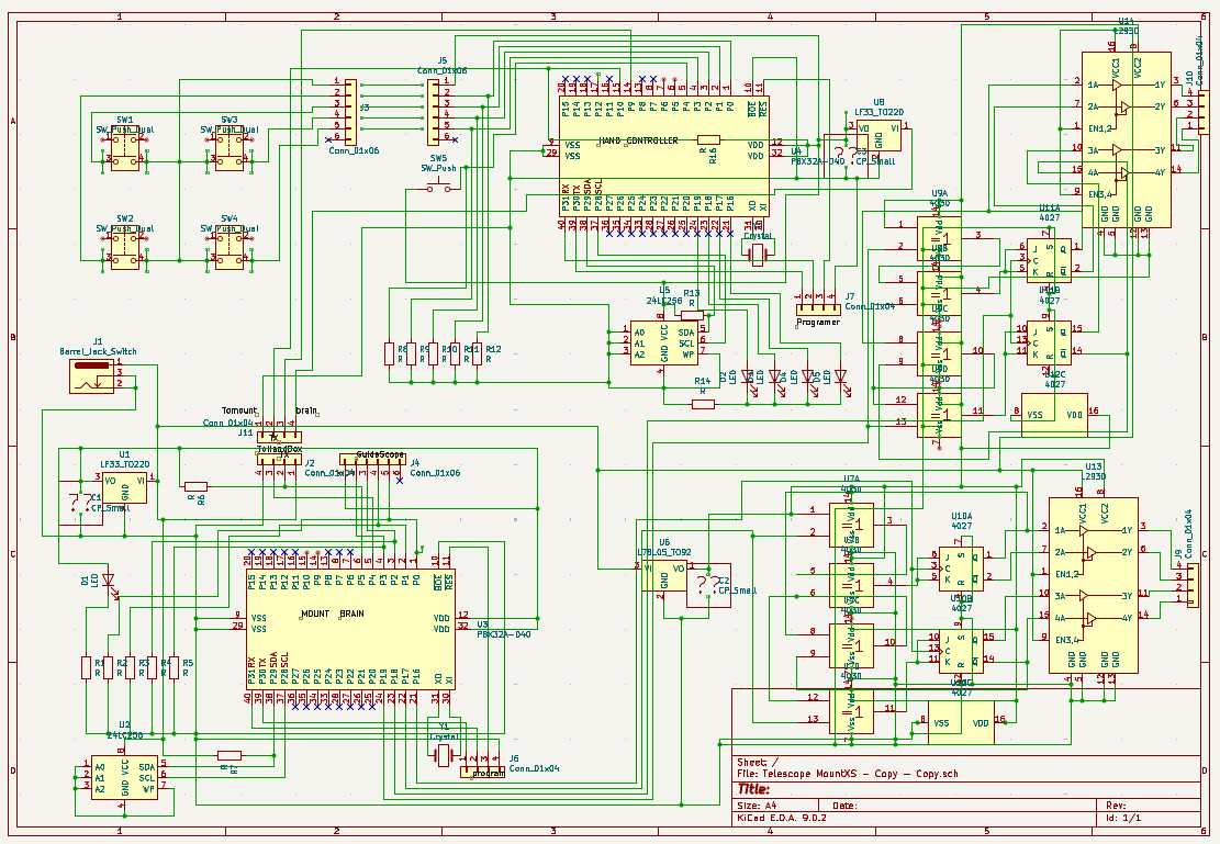
so you now have sent a choice of 3 (!!!) propeller boards, and we can now guess if the last picture shows the board, that you don't use any more for handbox or motor driver.
Your schematic does obviously not match the master board, which shows switching regulator modules!
**It is not us, who need accurate and reliable information about your setup. It is you who wants to go forward with this project. It is you, who wants help and therefore needs to make sure that we have consistent, full information. **
And no, if you had a look into the datasheets, then you would have found, that you need condensers on both sides of the linear regulators. These must be attached with very short leads.
From: https://www.st.com/resource/en/datasheet/lfxx.pdf
The L293 also needs condensers and probably heatsinks:
"10 Power Supply Recommendations
VCC1 is 5 V ± 0.5 V and VCC2 can be same supply as VCC1 or a higher voltage supply with peak voltage up to 36
V. Bypass capacitors of 0.1 uF or greater should be used at VCC1 and VCC2 pins. There are no power up or
power down supply sequence order requirements.
Properly heatsinking the L293 when driving high-current is critical to design. The Rthj-amp of the L293 can be
reduced by soldering the GND pins to a suitable copper area of the printed circuit board or to an external heat
sink."
From: https://www.ti.com/lit/ds/symlink/l293.pdf
I would add a protection diode against reverse voltage at the power input.
Also I would add an additional LARGE capacitor nearby the L293, because you do not want to disturb the power supply by each step.
You have lost many months in your project, because you did not take power supply seriously before. And it is most alarming, that you might have damaged the P1. In my experience these are quite robust. So if the P1 is damaged, then something is wrong with you hardware!!!!!
So now we have:
A0) Add all condensers nearby all chips and regulators and a protection diode against voltage reversal to the setup.
A1) Draw a schematic, that truly and completely reflects your setup including power supplies.
A2) Check the hardware against anything that might have killed P1.
A3) Measure all voltages.
A4) Load the sender software onto the handbox and make sure with a terminal on pins 30/31 that the buttons work.
B ) Check with an oscilloscope on pin 10, that there is output from the serial line.
C) Check with an oscilloscope on pin 5 of the receiver, that there is input from the serial line.
D) When C works next step is to load the receiver onto the mount box and make sure with a terminal on pins 30/31 that the codes are received.
E) After each step write a detailed report what you have done, how you have done it (to be able to repeat it a few weeks later). What was the result and what is the conclusion.
F) Send photographs showing that you really added the condensers.
Perhaps someone can give a nice translation of this verse:
"Was ich tue ganz in Ruhe und mit Mut, das wird gut."
@Mickster said:
I don't get it. I'm not exactly a programming wizard but I created a class for fdserial in FlexBasic and without fuss, I was talking to four multi-dropped RP2040s at 921,600 Baud. Nothing to figure out or debug.
Hi,
if you say, that you had nothing to figure out or debug, than this will be because you have done similar things in the past and learned a lot.
As far as I understand, @bbrien is fighting with the following problems:
1. He is trying to do this with a really low budget. So he does not use any proven modules but makes his boards from scratch. In my opinion this is not cheaper in the end and it is certainly much more difficult!
2. He is not accustomed to such projects, so he has not learned that we all (!) need documentation to be able to go on after some break of some months/weeks. This has lead to going in awful circles.
3. He is trying to get this project going quickly. Unfortunately he has tried to gain time omitting steps and doing more than one step at a time. The combination to want to save time AND money makes the project very difficult.
4. He does not do such projects normally, so he has to learn a whole lot but wants to have the solution NOW. This is outright impossible.
5. There is no datasheet for these motors, so it was unclear for a long time how to drive them.
6. He has up to now not accepted that power supply is a central element of such project. This has lead to destroyed parts and also a very long delay of months, because trials to drive the motors did not work because of weak power supply.
7. This project is in my opinion really not simple: It involves communication between two units over several meters. Drive two step motors in parallel for linear movement. Some sort of multitasking, because the buttons override a constant basic linear movement with constant speed and direction.
8. Communication about a project is never easy. I have learned, that a Forum is a very limited means of communication. It is very difficult to debug something using a Forum. I hope that bbrien will see, that he has to invest time into good clear communication, because every question means at the very least a delay of one day.
I do agree with you very much, that it is very unfortunate that the standard language of P1 is a special language "SPIN" and I also think, that BASIC would be better here. But this is only one brick of the difficulties and several people have written code for bbrien, so a restart (with PropBasic?) will probably not be helpful. In this case SPIN is fast enough. P1 was chosen and the hardware is soldered. I think, that the project is "nearly there", perhaps 90 percent or even better!
Concerning power supplies, my supplies are from a 14.4VDC Lithium battery which use buck converters to provide the required main voltage which in this case is 9 VDC . The Primary control board uses a .5 uf disk cap on input, a 220 uf el. cap on output and a Lf33V regulator to provide a stable 3.3V to the Prop power, then the control board output delivers a 9V source by means of an internal bus. The Driver boards are powered by buck converters delivering 6V. each Board also has a 220 mf cap input of thel293D. VDD handled by L78L05 regulators W/ 100mf caps
Purpose of each unit is this; (Equatorial Mount)
"Mount Brain 1;produce a pulse to operate a stepper connected by series of gears(not all accessible) to the central shaft(right ascension), which tracks stars moving East to west. another pulse delivered to a second motor(declination Shaft)which is controlled from either a auto-guider Port or a secondary hand controller, which also contains a right ascension control. this controller also sets the speeds for the Right ascension and declination motors for high speed slewing( thus the need for a second processor). The auto-guider port also has aright ascension pins for guiding while interrupting the normal function of tracking.
Mount BS19B has been loaded into the mount brain the mount brain tested under full run with motors attached. RA motor moves as it usually does no hand box attached and no inputs to the auto-guider port there should be no other signals coming from the control board but I have a signal coming off the declination motor enable pin of one hertz at 3.3V.Not supposed to be any signal ant this time. please check program
Hi @bbrien,
to avoid going in circles again, I have made this checklist for this project. I can support you further, AFTER these tasks are done. You need a solid fundament to go on.
A0) Add all condensers nearby all chips and regulators and a protection diode against voltage reversal to the setup.
A1) Draw a schematic, that truly and completely reflects your setup including power supplies.
A2) Check the hardware against anything that might have killed P1.
A3) Measure all voltages.
A4) Load the sender software onto the handbox and make sure with a terminal on pins 30/31 that the buttons work.
B ) Check with an oscilloscope on pin 10, that there is output from the serial line.
C) Check with an oscilloscope on pin 5 of the receiver, that there is input from the serial line.
D) When C works next step is to load the receiver onto the mount box and make sure with a terminal on pins 30/31 that the codes are received.
E) After each step write a detailed report what you have done, how you have done it (to be able to repeat it a few weeks later). What was the result and what is the conclusion.
F) Send photographs showing that you really added the condensers.
these are the first photos and programs. The photos are of my primary power supply, it can deliver 6,9,12volts at up to 3 amps. my steppers only draw about 200ma at full drive and will not move if no power is delivered. the gearbox will not allow any back movement even if you try to move the scope by hand.am searching for shorted terminals on the guider switches ,will continue later.
Against better knowledge I did have a look into Mount BS19B. It convinces me that any work is in vain before the checklist is done properly. You absolutely need a schematic, which is trustworthy and complete. And you will then need to have terminal program connected to the mount. But to really test the mount device you first need a proven hand box sender. So the order of steps in the checklist makes a lot of sense!
But I can assure you, that this program indeed has non-zero speed on both motors, as you could have found out yourself. (If this project was mine, I would connect two potentiometers for these two basic AUTO-RATES, perhaps we you can add this AFTER it works.)
Do not do any changements to these both programs, or we will loose my proving of #121!!!
"got the GEAR simulator working also for the sender and tested with NORTH and SOUTH buttons, which both send the correct code. So these two files here in this post do compile and should work together regarding protocol."
@bbrien said:
these are the first photos and programs. The photos are of my primary power supply, it can deliver 6,9,12volts at up to 3 amps. my steppers only draw about 200ma at full drive and will not move if no power is delivered. the gearbox will not allow any back movement even if you try to move the scope by hand.am searching for shorted terminals on the guider switches ,will continue later.
What on earth are you doing?
T_Mount BS20.spin is totally reformatted against the proven T_Mount B19.spin and does not compile any more.
These are the steps and their order to do:
A0) Add all condensers nearby all chips and regulators and a protection diode against voltage reversal to the setup.
A1) Draw a schematic, that truly and completely reflects your setup including power supplies.
A2) Check the hardware against anything that might have killed P1.
A3) Measure all voltages.
A4) Load the sender software onto the handbox and make sure with a terminal on pins 30/31 that the buttons work.
B ) Check with an oscilloscope on pin 10, that there is output from the serial line.
C) Check with an oscilloscope on pin 5 of the receiver, that there is input from the serial line.
D) When C works next step is to load the receiver onto the mount box and make sure with a terminal on pins 30/31 that the codes are received.
E) After each step write a detailed report what you have done, how you have done it (to be able to repeat it a few weeks later). What was the result and what is the conclusion.
F) Send photographs showing that you really added the condensers.
Please do not send any more schematic until it completely fulfils:
A0) Add all condensers nearby all chips and regulators and a protection diode against voltage reversal to the setup.
A1) Draw a schematic, that truly and completely reflects your setup including power supplies.
@bbrien
please don't take this as rudeness of mine. But I do think, that you need someone, who must sit there with your real hardware and get this working for you or sit there with you together at the same desk and get it working with you. Neither these schematics, nor these programs, nor communication over such complex technical project via a forum is your world. And you either have no time or do not want to spend the necessary time.
Don't you want to ask someone for hands-on local help?
@bbrien said:
don't know anyone in the area that can do. tried your programs but all tjhat happened is it burned out both chips now I am waiting for new ones.
Hm,
I am at a total loss, how we could help you. You certainly did NOT follow my step by step list.
YOU HAVE TO CHECK YOUR HARDWARE!!!! The only way to kill the P1 is either over-voltage (measure it!!!!) at any pin or current too high at a single pin or the sum of current too high. So please check all connections and PIN numbers. Which pin is an output and which is an input? The serial output must be connected to an input.
According to your schematics you have had the eeprom connected to ???12V???
DO NOT INSERT NEW CHIPS UNTIL YOU HAVE CHECKED EVERYTHING VERY CAREFULLY AND HAVE DRAWN FULLY TRUE SCHEMATICS.
That is what stymies me the most is the circuit diagrams between the LX50, the STAR Finder 10, and the Orion EQ2 are virtually the same except with the output section , in the LX50 the outputs from the processor go to the L298 board with inverters on a2 and a4 inputs and b2 and b4 inputs with the enables tied to the respective pulse lines for motors 1 and 2. In the 10 inch Star Finder which has one stepper and 1 DC geared clock motor( 5v at 150ma). there is 1/2 L293 driving the DC clock motor and a MC3479 stepper driver(RamseySMD1) running the stepper. these two units work perfectly and are housed in Thailand on my Property.
Well, If you already have one system with 2 step motors and a remote control handbox running perfectly, I do not understand, why you do not just do an exact copy of hardware and software?
(The way you use the signal name "enable" seems to be different to how it is used elsewhere.)
The two units in Thailand do not have 2 steppers. One has two DC clock motors ,two motors and two wires each(LX50). and other one stepper and one DC clock motor. the L293 and L298 and UDN2993 and MC3479 all use term enable in their pin designations. I'm also beginning to think that someone may have inadvertently given me a virus with their program.
Perhaps I should tell something to explain, why I think power supply is so very important.
I once had a project with an esp32 module, which kept crashing. And I didn't understand and could not find my bug.
Then I discovered with an oscilloscope that the 3V3 power rail was oscillating up to 9V! I was very astonished, that the esp32 survived.
My second topic on serial , in the case of the hand box the tx pin is pulled up to 3.3v and the rx pin is pulled to ground level. but what about the mount system, should they also be pulled to their prospective levels.?
@bbrien said:
My second topic on serial , in the case of the hand box the tx pin is pulled up to 3.3v and the rx pin is pulled to ground level. but what about the mount system, should they also be pulled to their prospective levels.?
Your schematic tells a different story?
What resistors do you use?
Often pull-up or pull down is done only on the receiver side.


Comments
Sorry ,another bad on my part, I should have sent EQ@-B instead . please change the tx and rx pins to rx =5 and tx=6 Also check the download on the schematic it should have a "copy" at the end ,if not then download again. Thanks
Oh, @bbrien,
so once again no thank you but once again another single file and not an archive but needs a special serial and does not compile. And it scans some local knobs, instead of some serial connection to a handbox.
Your threads seem to be something like a social experiment about the patience and the need of forum members to show off their competence?
Or just count, how many idiots chime in?
If this is not meant as a social experiment, then you can take the two archives of my post #121 as they seem to come near your goals.
And do the steps, that I mentioned there.
When you have
then I might try to help you again.
Christof
I don't get it. I'm not exactly a programming wizard but I created a class for fdserial in FlexBasic and without fuss, I was talking to four multi-dropped RP2040s at 921,600 Baud. Nothing to figure out or debug.
The devices have all of the required capacitors.
I have already downloaded the two programs that you have modified.
I have already loaded the devices with the new programs but am having problems with the simulator(red package), may have damaged the processor, waiting for new one. am setting up the big box in the meantime. Will report in a few days. " Thank you"
Hi,
so you now have sent a choice of 3 (!!!) propeller boards, and we can now guess if the last picture shows the board, that you don't use any more for handbox or motor driver.
Your schematic does obviously not match the master board, which shows switching regulator modules!
**It is not us, who need accurate and reliable information about your setup. It is you who wants to go forward with this project. It is you, who wants help and therefore needs to make sure that we have consistent, full information. **
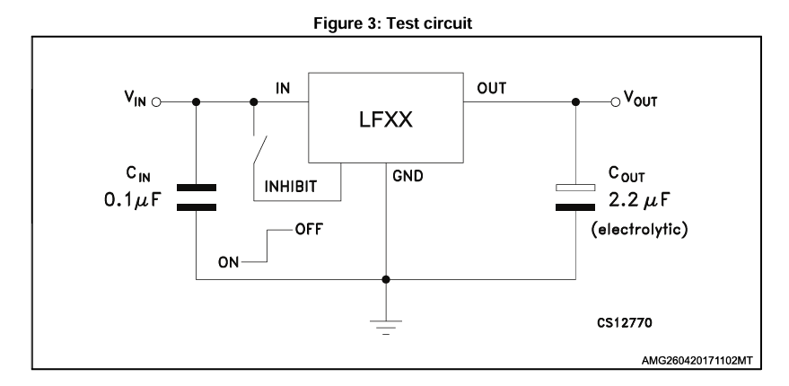
And no, if you had a look into the datasheets, then you would have found, that you need condensers on both sides of the linear regulators. These must be attached with very short leads.
From: https://www.st.com/resource/en/datasheet/lfxx.pdf
The L293 also needs condensers and probably heatsinks:
"10 Power Supply Recommendations
VCC1 is 5 V ± 0.5 V and VCC2 can be same supply as VCC1 or a higher voltage supply with peak voltage up to 36
V. Bypass capacitors of 0.1 uF or greater should be used at VCC1 and VCC2 pins. There are no power up or
power down supply sequence order requirements.
Properly heatsinking the L293 when driving high-current is critical to design. The Rthj-amp of the L293 can be
reduced by soldering the GND pins to a suitable copper area of the printed circuit board or to an external heat
sink."
From:
https://www.ti.com/lit/ds/symlink/l293.pdf
And for each chip on the propeller boards:
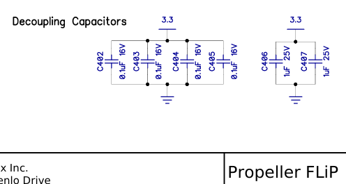
From: https://www.parallax.com/package/propeller-flip-module-downloads/
I would add a protection diode against reverse voltage at the power input.
Also I would add an additional LARGE capacitor nearby the L293, because you do not want to disturb the power supply by each step.
You have lost many months in your project, because you did not take power supply seriously before. And it is most alarming, that you might have damaged the P1. In my experience these are quite robust. So if the P1 is damaged, then something is wrong with you hardware!!!!!
So now we have:
A0) Add all condensers nearby all chips and regulators and a protection diode against voltage reversal to the setup.
A1) Draw a schematic, that truly and completely reflects your setup including power supplies.
A2) Check the hardware against anything that might have killed P1.
A3) Measure all voltages.
A4) Load the sender software onto the handbox and make sure with a terminal on pins 30/31 that the buttons work.
B ) Check with an oscilloscope on pin 10, that there is output from the serial line.
C) Check with an oscilloscope on pin 5 of the receiver, that there is input from the serial line.
D) When C works next step is to load the receiver onto the mount box and make sure with a terminal on pins 30/31 that the codes are received.
E) After each step write a detailed report what you have done, how you have done it (to be able to repeat it a few weeks later). What was the result and what is the conclusion.
F) Send photographs showing that you really added the condensers.
Perhaps someone can give a nice translation of this verse:
"Was ich tue ganz in Ruhe und mit Mut, das wird gut."
Christof
@bbrien
to obtain a readable version for the schematic you can copy and paste via snipping tool as described by Jon.
Hi,
if you say, that you had nothing to figure out or debug, than this will be because you have done similar things in the past and learned a lot.
As far as I understand, @bbrien is fighting with the following problems:
1. He is trying to do this with a really low budget. So he does not use any proven modules but makes his boards from scratch. In my opinion this is not cheaper in the end and it is certainly much more difficult!
2. He is not accustomed to such projects, so he has not learned that we all (!) need documentation to be able to go on after some break of some months/weeks. This has lead to going in awful circles.
3. He is trying to get this project going quickly. Unfortunately he has tried to gain time omitting steps and doing more than one step at a time. The combination to want to save time AND money makes the project very difficult.
4. He does not do such projects normally, so he has to learn a whole lot but wants to have the solution NOW. This is outright impossible.
5. There is no datasheet for these motors, so it was unclear for a long time how to drive them.
6. He has up to now not accepted that power supply is a central element of such project. This has lead to destroyed parts and also a very long delay of months, because trials to drive the motors did not work because of weak power supply.
7. This project is in my opinion really not simple: It involves communication between two units over several meters. Drive two step motors in parallel for linear movement. Some sort of multitasking, because the buttons override a constant basic linear movement with constant speed and direction.
8. Communication about a project is never easy. I have learned, that a Forum is a very limited means of communication. It is very difficult to debug something using a Forum. I hope that bbrien will see, that he has to invest time into good clear communication, because every question means at the very least a delay of one day.
I do agree with you very much, that it is very unfortunate that the standard language of P1 is a special language "SPIN" and I also think, that BASIC would be better here. But this is only one brick of the difficulties and several people have written code for bbrien, so a restart (with PropBasic?) will probably not be helpful. In this case SPIN is fast enough. P1 was chosen and the hardware is soldered. I think, that the project is "nearly there", perhaps 90 percent or even better!
Cheers, Christof
Concerning power supplies, my supplies are from a 14.4VDC Lithium battery which use buck converters to provide the required main voltage which in this case is 9 VDC . The Primary control board uses a .5 uf disk cap on input, a 220 uf el. cap on output and a Lf33V regulator to provide a stable 3.3V to the Prop power, then the control board output delivers a 9V source by means of an internal bus. The Driver boards are powered by buck converters delivering 6V. each Board also has a 220 mf cap input of thel293D. VDD handled by L78L05 regulators W/ 100mf caps
Purpose of each unit is this; (Equatorial Mount)
"Mount Brain 1;produce a pulse to operate a stepper connected by series of gears(not all accessible) to the central shaft(right ascension), which tracks stars moving East to west. another pulse delivered to a second motor(declination Shaft)which is controlled from either a auto-guider Port or a secondary hand controller, which also contains a right ascension control. this controller also sets the speeds for the Right ascension and declination motors for high speed slewing( thus the need for a second processor). The auto-guider port also has aright ascension pins for guiding while interrupting the normal function of tracking.
Mount BS19B has been loaded into the mount brain the mount brain tested under full run with motors attached. RA motor moves as it usually does no hand box attached and no inputs to the auto-guider port there should be no other signals coming from the control board but I have a signal coming off the declination motor enable pin of one hertz at 3.3V.Not supposed to be any signal ant this time. please check program
Hi @bbrien,
to avoid going in circles again, I have made this checklist for this project. I can support you further, AFTER these tasks are done. You need a solid fundament to go on.
A0) Add all condensers nearby all chips and regulators and a protection diode against voltage reversal to the setup.
A1) Draw a schematic, that truly and completely reflects your setup including power supplies.
A2) Check the hardware against anything that might have killed P1.
A3) Measure all voltages.
A4) Load the sender software onto the handbox and make sure with a terminal on pins 30/31 that the buttons work.
B ) Check with an oscilloscope on pin 10, that there is output from the serial line.
C) Check with an oscilloscope on pin 5 of the receiver, that there is input from the serial line.
D) When C works next step is to load the receiver onto the mount box and make sure with a terminal on pins 30/31 that the codes are received.
E) After each step write a detailed report what you have done, how you have done it (to be able to repeat it a few weeks later). What was the result and what is the conclusion.
F) Send photographs showing that you really added the condensers.
these are the first photos and programs. The photos are of my primary power supply, it can deliver 6,9,12volts at up to 3 amps. my steppers only draw about 200ma at full drive and will not move if no power is delivered. the gearbox will not allow any back movement even if you try to move the scope by hand.am searching for shorted terminals on the guider switches ,will continue later.
Against better knowledge I did have a look into Mount BS19B. It convinces me that any work is in vain before the checklist is done properly. You absolutely need a schematic, which is trustworthy and complete. And you will then need to have terminal program connected to the mount. But to really test the mount device you first need a proven hand box sender. So the order of steps in the checklist makes a lot of sense!
But I can assure you, that this program indeed has non-zero speed on both motors, as you could have found out yourself. (If this project was mine, I would connect two potentiometers for these two basic AUTO-RATES, perhaps we you can add this AFTER it works.)
Do not do any changements to these both programs, or we will loose my proving of #121!!!
"got the GEAR simulator working also for the sender and tested with NORTH and SOUTH buttons, which both send the correct code. So these two files here in this post do compile and should work together regarding protocol."
What on earth are you doing?


T_Mount BS20.spin is totally reformatted against the proven T_Mount B19.spin and does not compile any more.
These are the steps and their order to do:
A0) Add all condensers nearby all chips and regulators and a protection diode against voltage reversal to the setup.
A1) Draw a schematic, that truly and completely reflects your setup including power supplies.
A2) Check the hardware against anything that might have killed P1.
A3) Measure all voltages.
A4) Load the sender software onto the handbox and make sure with a terminal on pins 30/31 that the buttons work.
B ) Check with an oscilloscope on pin 10, that there is output from the serial line.
C) Check with an oscilloscope on pin 5 of the receiver, that there is input from the serial line.
D) When C works next step is to load the receiver onto the mount box and make sure with a terminal on pins 30/31 that the codes are received.
E) After each step write a detailed report what you have done, how you have done it (to be able to repeat it a few weeks later). What was the result and what is the conclusion.
F) Send photographs showing that you really added the condensers.
l
Loaded handboxDH9A1A into hand controller and this is what I get.
to read schematics use Kicad.
Hm, what is this supposed to be?
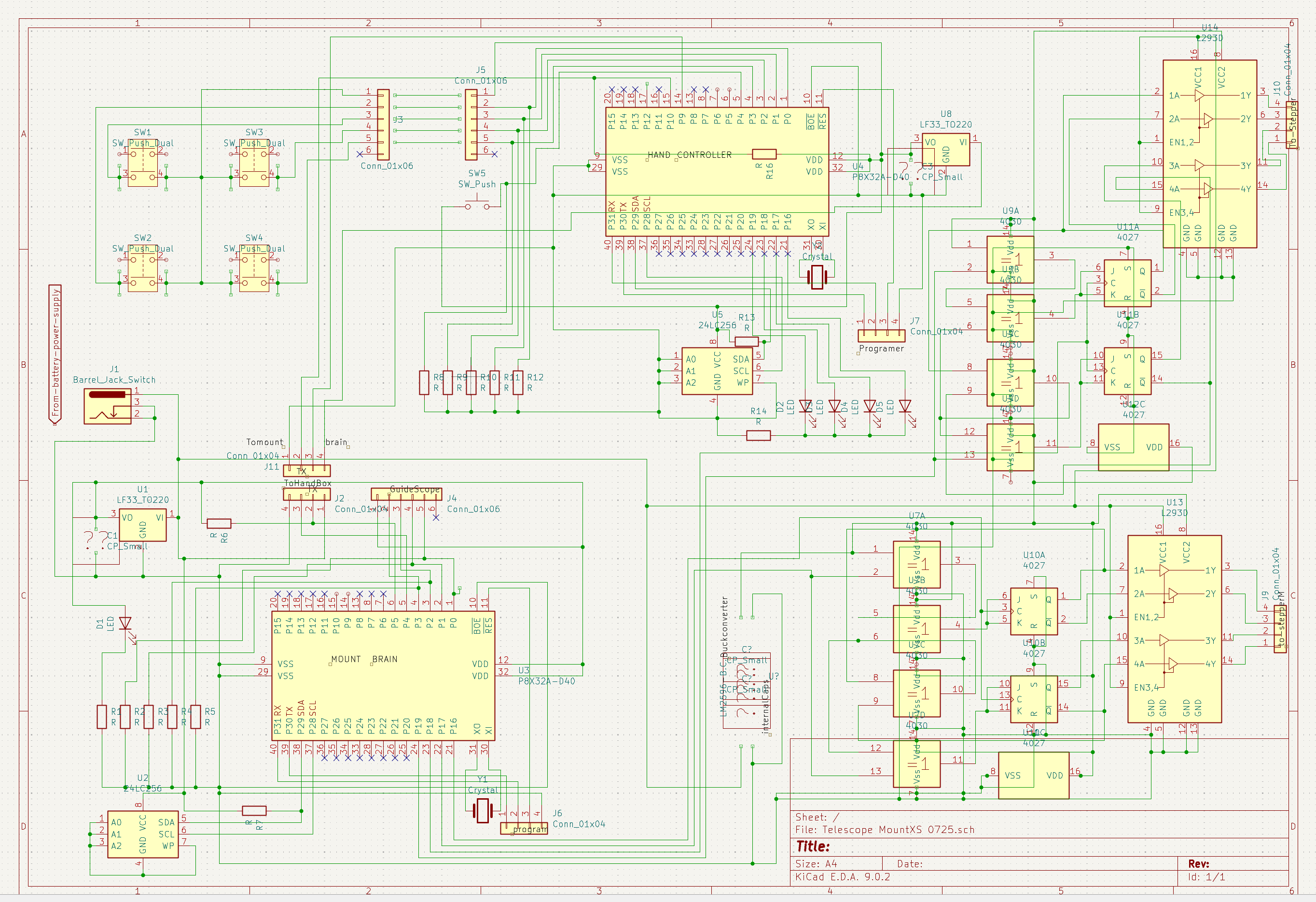
Your photo shows two buck converters and also it probably shows a 78L05 (or some other TO92 device) on each of the driver modules?
The eeprom is supplied still or again via high voltage. We had discussed this on 20250623 a month now. #127 https://forums.parallax.com/discussion/173757/dual-stepper-motors#latest

Going in circles. What a waste of time.
It is necessary to give the schematic file name version numbers!
Please do not send any more schematic until it completely fulfils:
A0) Add all condensers nearby all chips and regulators and a protection diode against voltage reversal to the setup.
A1) Draw a schematic, that truly and completely reflects your setup including power supplies.
@bbrien
please don't take this as rudeness of mine. But I do think, that you need someone, who must sit there with your real hardware and get this working for you or sit there with you together at the same desk and get it working with you. Neither these schematics, nor these programs, nor communication over such complex technical project via a forum is your world. And you either have no time or do not want to spend the necessary time.
Don't you want to ask someone for hands-on local help?
don't know anyone in the area that can do. tried your programs but all tjhat happened is it burned out both chips now I am waiting for new ones.
Hm,
I am at a total loss, how we could help you. You certainly did NOT follow my step by step list.
I have never killed a P1, they are quite robust.
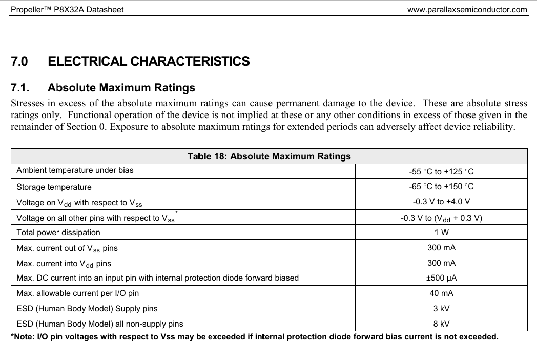
See here: https://www.parallax.com/package/p8x32a-propeller-datasheet/
YOU HAVE TO CHECK YOUR HARDWARE!!!! The only way to kill the P1 is either over-voltage (measure it!!!!) at any pin or current too high at a single pin or the sum of current too high. So please check all connections and PIN numbers. Which pin is an output and which is an input? The serial output must be connected to an input.
According to your schematics you have had the eeprom connected to ???12V???
DO NOT INSERT NEW CHIPS UNTIL YOU HAVE CHECKED EVERYTHING VERY CAREFULLY AND HAVE DRAWN FULLY TRUE SCHEMATICS.
That is what stymies me the most is the circuit diagrams between the LX50, the STAR Finder 10, and the Orion EQ2 are virtually the same except with the output section , in the LX50 the outputs from the processor go to the L298 board with inverters on a2 and a4 inputs and b2 and b4 inputs with the enables tied to the respective pulse lines for motors 1 and 2. In the 10 inch Star Finder which has one stepper and 1 DC geared clock motor( 5v at 150ma). there is 1/2 L293 driving the DC clock motor and a MC3479 stepper driver(RamseySMD1) running the stepper. these two units work perfectly and are housed in Thailand on my Property.
Well, If you already have one system with 2 step motors and a remote control handbox running perfectly, I do not understand, why you do not just do an exact copy of hardware and software?
(The way you use the signal name "enable" seems to be different to how it is used elsewhere.)
The two units in Thailand do not have 2 steppers. One has two DC clock motors ,two motors and two wires each(LX50). and other one stepper and one DC clock motor. the L293 and L298 and UDN2993 and MC3479 all use term enable in their pin designations. I'm also beginning to think that someone may have inadvertently given me a virus with their program.
Hm, these source codes are not very long. So if you take the time to try to understand them, then you will discover that they contain no virus.
Perhaps I should tell something to explain, why I think power supply is so very important.
I once had a project with an esp32 module, which kept crashing. And I didn't understand and could not find my bug.
Then I discovered with an oscilloscope that the 3V3 power rail was oscillating up to 9V! I was very astonished, that the esp32 survived.
According to the file that I just sent, the 3.3v power rail has no oscillations at all , clean and filtered
My second topic on serial , in the case of the hand box the tx pin is pulled up to 3.3v and the rx pin is pulled to ground level. but what about the mount system, should they also be pulled to their prospective levels.?
Your schematic tells a different story?
What resistors do you use?
Often pull-up or pull down is done only on the receiver side.
If you're using True mode serial, this is a bad idea. In True mode, the idle state of TX and RX is high.
10K ohm resistors.