@Rayman said:
@Wuerfel_21 are there free cycles in your video drivers during blanking?
Looking for places to add some extra code…
Extra code to do what?
There's a bunch of places you can add code:
run_emulator main loop. This is where features like handling quit-to-menu and NVRAM persistence is handled. This is easiest because it's compiled Spin2, but doesn't exist in NeoYume! Tempest 2000 has a similar Spin2 main loop somewhere.
Input cog. If not using the USB driver, it's fairly easy to do many things in the input handling cog. Modifying the USB driver is harder, but since input handling is simple and similar between projects, this would be the most portable way to implement a background task.
Adding code to to MegaVGA/NeoVGA/MisoVGA/TempestVGA and friends is more tricky because there's a lot of timing going on and most code-paths are reused for many differently timed modes. The codebase is also slightly different for each project, despite attempts to sync them. I guess hooking the blankline_func (for outputting a front/back porch blank line) is the least dangerous.
I wouldn't recommend messing with any of the emulator lower code.
@Rayman said:
@Wuerfel_21 Do you have a recommendation for screen orientation?
Does this look good?
A screen should be oriented such that the picture appears the right way up, for some definition of right way.
If I see correctly, this is an adapter for the ER-TFTM023 breakout board. The big pin header is logically the bottom, even if the silk text disagrees. So this would have the bottom row of the display facing outwards from the mother board, for better or worse. Probably good for using it on the desk.
IIRC switching the screen orientation in software didn't work when I tried it, so you'd be stuck with that. Can give it another try though.
DISCTRL or MADCTL can be used to change screen orientation.
Vertical flip works by changing gate driver scan order -> works
Horizontal flip works by changing memory write addressing -> oops, ignored in memory bypass mode
Disabling memory bypass causes a different bug to appear (320th column is missing) and possibly causes latency (haven't confirmed that)
(Flipping vertically only inverts the chirality of all the text, so is not usable)
(Also lamo my browser's autocorrect dictionary doesn't know what chirality is)
@Rayman said:
@Wuerfel_21 thinking the lcd6 driver can be made to work with a generic qvga buffer, is that true? Is that a lot of work or simple?
It's a bit of work. First you may want to grab the version from Tempest 2000, because that one is set up to for 320x240 (rather than 320x224 or 256x224 or any of that nonsense). Then you can set the buflines parameter to 240 to use a full frame buffer instead of line buffers. Unfortunately, this will consume 300K of memory at 32bpp. Changing the color format would be some more work. In the end, this is the emulator-focused video driver with all the quirks that come from that. I just never made a more standalone LCD6 driver. Not that that's not possible. Feel free to copy some of my init code under init_ili9342. Though some of it is harder to understand because variables from NTSC encoding are re-used for LCD6-specifc parameters.
(Also note that nothing stops you from using the more usual controller-buffered SPI graphics stuff, which I think a Spin library exists for somewhere - just need to make sure that code properly resets the LCD so isn't stuck in RGB mode)
If you just want to display some text, just copy that stuff from the memory tester program (or rather, remove all the memory test stuff until you're just left with the text driver). That one is already set up to work with the NeoVGA driver, though you may need to bring in a newer version from NeoYume proper for correct LCD6 support (don't remember when that one branched off).
Toying with this idea that might take out 3 or 4 birds with one stone...
Can add extra P2 to a P2 with at least an 8 bit bus between them.
Can daisy chain multiple displays using ffc and 40-pin connectors...
Can be a stand alone P2 board
The square hole in the middle might make 2 layer wiring tough...
That needs to get 1.8 Volts from somewhere. I wouldn't want to pull from the two 3.3 Volt regulated pins. That still leaves three options:
Use the two 5 Volt pins. They're typically directly from a heavier supply. And given very few add-on boards even connect them at all there's a possible option to further boost voltage. 12 Volts maybe.
The 40 pin header may have a supply from it, but I suspect not.
Have a dedicated supply connector. Most robust option but also most inconvenient.
PS: If attempting raised supply voltages then it becomes important to get into the habit, if you haven't already, of powering everything down before plugging and unplugging add-on boards.
@Rayman said:
Wondering if several P2 pins could be tied together in order to drive a speaker...
I had some code at some point to use 2 pins to drive symmetric audio (so double the peak-2-peak voltage), but I don't think that ever made it to the emulator code bases, I think I only had a hacked version of OPNAcog with that.
But, maybe console output is digital and counts on amp to cut off high freq?
Some of the emulators have built-in low-pass filtering because the raw signal sounds too harsh.
Another thing to note is that the P2 DACs are zero-order hold (stairstep-like signal), so frequencies close to the nyquist limit are attenuated slightly and high-frequency images are present:
Small speakers usually have poor frequency response, so an amplifier circuit tuned to make up for it (i.e. if speaker is weak at low frequencies, boost those) can increase quality a lot.
No such thing. I don't think it'd be difficult to cut it into shape to make it work, but maintaining that for version updates won't be fun (and you really don't want to get stuck with outdated usbnew)


Comments
Son is ok with screen size so might make mini console using it
Make make flip screen that bolts to bottom of snes gamepad
Any idea what freq range the audio is?
???
It's just normal audio
Need to pick out tiny speakers…
@Wuerfel_21 are there free cycles in your video drivers during blanking?
Looking for places to add some extra code…
Extra code to do what?
There's a bunch of places you can add code:
run_emulatormain loop. This is where features like handling quit-to-menu and NVRAM persistence is handled. This is easiest because it's compiled Spin2, but doesn't exist in NeoYume! Tempest 2000 has a similar Spin2 main loop somewhere.blankline_func(for outputting a front/back porch blank line) is the least dangerous.@Wuerfel_21 Do you have a recommendation for screen orientation?
Does this look good?
A screen should be oriented such that the picture appears the right way up, for some definition of right way.
If I see correctly, this is an adapter for the ER-TFTM023 breakout board. The big pin header is logically the bottom, even if the silk text disagrees. So this would have the bottom row of the display facing outwards from the mother board, for better or worse. Probably good for using it on the desk.
IIRC switching the screen orientation in software didn't work when I tried it, so you'd be stuck with that. Can give it another try though.
Ok, thanks. Guess will try like this and see if it works. Think there's enough free pins to add USB and audio, but need to check...
I messed with the screen orientation again:
(Flipping vertically only inverts the chirality of all the text, so is not usable)
(Also lamo my browser's autocorrect dictionary doesn't know what chirality is)
@Wuerfel_21 thinking the lcd6 driver can be made to work with a generic qvga buffer, is that true? Is that a lot of work or simple?
It's a bit of work. First you may want to grab the version from Tempest 2000, because that one is set up to for 320x240 (rather than 320x224 or 256x224 or any of that nonsense). Then you can set the
buflinesparameter to 240 to use a full frame buffer instead of line buffers. Unfortunately, this will consume 300K of memory at 32bpp. Changing the color format would be some more work. In the end, this is the emulator-focused video driver with all the quirks that come from that. I just never made a more standalone LCD6 driver. Not that that's not possible. Feel free to copy some of my init code underinit_ili9342. Though some of it is harder to understand because variables from NTSC encoding are re-used for LCD6-specifc parameters.(Also note that nothing stops you from using the more usual controller-buffered SPI graphics stuff, which I think a Spin library exists for somewhere - just need to make sure that code properly resets the LCD so isn't stuck in RGB mode)
If you just want to display some text, just copy that stuff from the memory tester program (or rather, remove all the memory test stuff until you're just left with the text driver). That one is already set up to work with the NeoVGA driver, though you may need to bring in a newer version from NeoYume proper for correct LCD6 support (don't remember when that one branched off).
Toying with this idea that might take out 3 or 4 birds with one stone...
Can add extra P2 to a P2 with at least an 8 bit bus between them.
Can daisy chain multiple displays using ffc and 40-pin connectors...
Can be a stand alone P2 board
The square hole in the middle might make 2 layer wiring tough...
That needs to get 1.8 Volts from somewhere. I wouldn't want to pull from the two 3.3 Volt regulated pins. That still leaves three options:
PS: If attempting raised supply voltages then it becomes important to get into the habit, if you haven't already, of powering everything down before plugging and unplugging add-on boards.
@evanh Thats the P2 SWaP module there….
Either powered by USB-C connector, 5v from connected P2, or lipo
Wondering if several P2 pins could be tied together in order to drive a speaker...
But, maybe console output is digital and counts on amp to cut off high freq?
I had some code at some point to use 2 pins to drive symmetric audio (so double the peak-2-peak voltage), but I don't think that ever made it to the emulator code bases, I think I only had a hacked version of OPNAcog with that.
Some of the emulators have built-in low-pass filtering because the raw signal sounds too harsh.
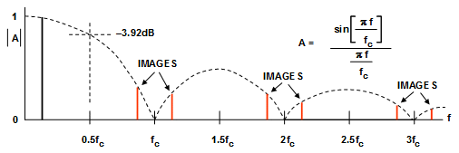
Another thing to note is that the P2 DACs are zero-order hold (stairstep-like signal), so frequencies close to the nyquist limit are attenuated slightly and high-frequency images are present:
Small speakers usually have poor frequency response, so an amplifier circuit tuned to make up for it (i.e. if speaker is weak at low frequencies, boost those) can increase quality a lot.
Wiring for this board is very inconvenient... Had to switch to 4 layers...
Think it's close now though...
You could make the board wider still. That would allow more routing space alongside the Prop2.
@evanh Maybe. Want to make a compact module though...
Think this is ready to go now. Be nice if it actually works...
@Wuerfel_21 Is there a version of USBNew that works with Prop Tool? Pretty sure not, but thought I'd ask...
No such thing. I don't think it'd be difficult to cut it into shape to make it work, but maintaining that for version updates won't be fun (and you really don't want to get stuck with outdated usbnew)
On another front, finally got around to testing this adapter for the 2p3" LCDs.
Works much better than the last version, that one was a disaster.
This one at least shows an image. Think that's a good sign.
But, it's been so long, forgot about some of the things on this board...
Has a place for SWaP module, so can be stand alone.
Also, has an audio amp and place to connect speakers.
There are some things that have to look up though...
Seems Megayume is getting pink screen of death with new Flexprop...
As if PSRAM timing is different...
Works with 6.9.10 but not 7.1.1 or 7.3.0
After reverting to FlexProp 6.9.10 can get Megayume running on the LCD6 adapter.
Seems somebody forgot to order the SMT usb connector, but fortunately, can turn thru hole into SMD with pliers...
Urgghghghghghghghg it's happening again?
Are you sure you're using the very latest MegaYume?
No, it might be old.
Looks like it's from April 15.
My MisoYume also won't compile, comes out around 20 bytes too big...
Hopefully, just need to download new versions then...