@Rayman said:
Are there any cogs with enough time to say read an analog brightness input and adjust PWM on a P2 pin to match?
I think that's basically just reading a smartpin, adjusting the value and writing to another smartpin, so that could really go anywhere.
So that would either go into the video driver or the input driver. Input driver I guess makes more sense because it's more easily shared/adapted between projects.
Though overall just putting whatever 8 pin peanut that does this in hardware on the board is least annoying. Or just don't, these LCDs don't get ultra bright to begin with.
No, that's definitely it. More likely: incorrect DOTCLK or serial connection.
The latter you can test if you have a driver for that specifically.
Or missing backlight pin (symptom of this is obvious).
Also, enabling RGB mode can cause the LCD controller to hang if there's no dot clock, so sometimes a power cycle is needed when experimenting.
What software are you testing with? Always use the latest version. I also don't think I ever tested the data bus not being at pin zero, might be missing a pin offset somewhere, so try that.
See also:
VIDEO_MODE = vconst.MODE_LCD6
VIDEO_SUBMODE = 0 ' Not used (yet)
ANALOG_BASEPIN = -1 ' Not used
VSYNC_PIN = (8<<0) + (9<<8) + (10<<16) + (11<<24) ' extra pins: DOTCLK<<0 + CS<<8 + CLK<<16 + SDA<<24
DIGITAL_BASEPIN = 0 ' HSync, VSync and 6 data pins
DIGITAL_REVERSED = false ' Not used


Comments
@Wuerfel_21 Looks like your LCD interface uses 12 pins, is that right?
So, two eval headers should leave 4 pins free for audio/USB?
Exactly. Would put audio there.
Can do both stereo and usb right?
Only if you drop the extra 2 pins (enable + LED) that the usual USB boards have.
All the audio is probably mono, right?
Would be nice to be able to turn off backlight and USB to save power...
No, all the emulators have stereo sound.
After the display is setup then the SPI signals, CLK and MOSI are free?
Yep, only needed during display init. Though IDK if the driver releases the pins properly.
Ok, that's great. Sounds like a simple driver fix, if it is needed...
There's a part that reads
            getbyte pb,extravpins,#1 ' CS high
            drvh pb
            getbyte pb,extravpins,#3 ' float SDA
            fltl pb
      _ret_ waitx #511
I guess that could just be changed to
getbyte pb,extravpins,#1 ' CS high drvh pb getbyte pb,extravpins,#2 ' float CLK fltl pb getbyte pb,extravpins,#3 ' float SDA fltl pb _ret_ waitx #511Are there any cogs with enough time to say read an analog brightness input and adjust PWM on a P2 pin to match?
USB enable, I don't know... Is there any use?
usb activity might be more interesting use...
I think that's basically just reading a smartpin, adjusting the value and writing to another smartpin, so that could really go anywhere.
So that would either go into the video driver or the input driver. Input driver I guess makes more sense because it's more easily shared/adapted between projects.
Though overall just putting whatever 8 pin peanut that does this in hardware on the board is least annoying. Or just don't, these LCDs don't get ultra bright to begin with.
Do yours have touchscreen? That takes away a bit of the brightness...
Thinking in terms of a handheld, where you want to turn off stuff but maybe not totally go dark...
No.
Yea. Though I'd assume running the P2 takes more power than the screen.
@Wuerfel_21 Can you post a pic of your 2.3" module? Want to see what resistors they left in...
Thinking 6-bit RGB interface is a special thing, not listed in their options.
Although, maybe it doesn't matter if data pins are open but not used...
It's a essentially the 3-pin SPI configuration, but with JP2 populated. You can specifically ask for this via email.
Appears mine has a zero ohm resistor to ground on all the 18-bit data bus lines. But can fix that with ohm meter and hot air gun…
That seems incorrect, there aren't even 18 jumpers to mess the data bus up like that.
Here's a shot of the correct jumper setup (also note populated JP2)
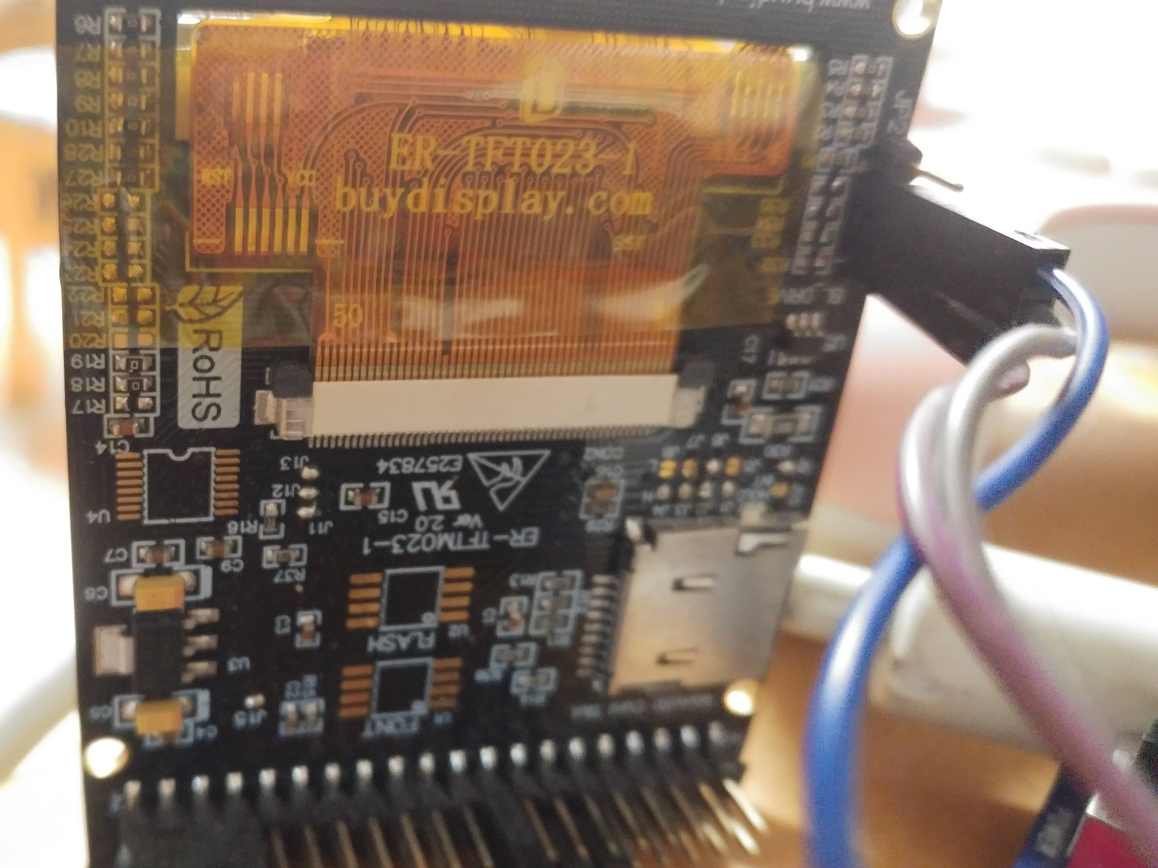
Not jumpers, all those 0402 resistors on the sides…
Those are effectively solder jumpers, they just populate them with zero-ohm 0402 because I guess that's easier in manufacturing.
@Wuerfel_21 Regarding ILI9342... What is the order of the 8 pins on the basepin?
This order doesn't seem to work:
HSync, VSync and 6 data pins@Rayman
No, that's definitely it. More likely: incorrect DOTCLK or serial connection.
The latter you can test if you have a driver for that specifically.
Or missing backlight pin (symptom of this is obvious).
Also, enabling RGB mode can cause the LCD controller to hang if there's no dot clock, so sometimes a power cycle is needed when experimenting.
What software are you testing with? Always use the latest version. I also don't think I ever tested the data bus not being at pin zero, might be missing a pin offset somewhere, so try that.
See also:
Ok basepin is 16, maybe that’s the problem
The backlight enable had me for a sec. They should have put a pull-up on that…
Problem might be with memory config... Think that has to work for NeoYume to work...
The menu should pop up regardless (unless RAM pins are interfering w/ something else)
Also don't forget the audio pins, make sure they're not set to some otherwise used pin.
Well, guess this counts as progress...
Better with newer NeoYume.
(Also moved to basepin P16)
That reads like "V1.2", are you really sure about that? 1.4 should be current, always grab from github when in doubt.
(Also the screen being upside down like that is normal, that's just how it's mounted)