

Single Sideband Transmitter
 SaucySoliton
Posts: 585
SaucySoliton
Posts: 585
I've been trying to figure out if the P2 can generate a clean enough RF signal. I guess the best way to find out is to do it and test. Also, it's neat that the P2 has enough hub memory for one minute of voice audio. 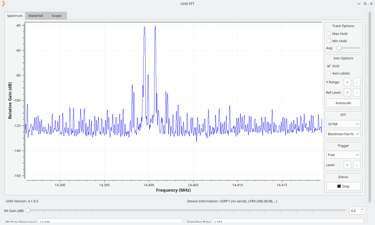
It doesn't work quite how you expect. As established here: https://forums.parallax.com/discussion/175003/hf-spectral-purity-comparison-p1-vs-p2 the signal from Goertzel mode is much cleaner than from the chroma modulator. But how to modulate the amplitude in Goertzel mode? Well, the DDS output can go to the color space converter. The CSC scales and mixes the signals together.
The problem with using the colorspace converter as an IQ modulator is the DAC input values are treated as Unsigned. If the CSC is used to reduce the sine wave amplitude, it would no longer average around Vcc/2. It would be nice to maintain a constant DC level regardless of the transmitted amplitude. Thankfully the CSC has 3 multiplier channels. I use the third channel as a constant to add a DC offset to compensate for varying sine and cosine output. There are other options to add DC offset to the CSC output. But the multipliers delay the signal by 4 clocks. I need the sine wave amplitude adjustment and the DC offset adjustment to happen at the exact same time. By routing everything through the CSC multipliers, the delay is equal. I haven't been able to rule out few transient samples after the CSC coefficient change. @cgracey Could you comment on whether adjustments to the CSC coefficients are glitch free? If the changes are limited to a few LSB, I wouldn't be able to see it on the scope, but it might affect RF spectral purity.
For a while I thought that I would need to do something like an Inverse Clarke Transform. Then I could add 3 positive sine waves together, at 120 degree phase offsets. But just doing IQ modulation and compensating for the varying DC offset is much faster computationally.
at 2.4MHz
signal -39
in-band spur (weaver artifact?) -77 (-38)
intermodulation spur -97 (-58)
spurs +-256khz (sample rate) -89 (-50)
2nd harmonic -91 (-52)
2rd harmonic -104 (-65)
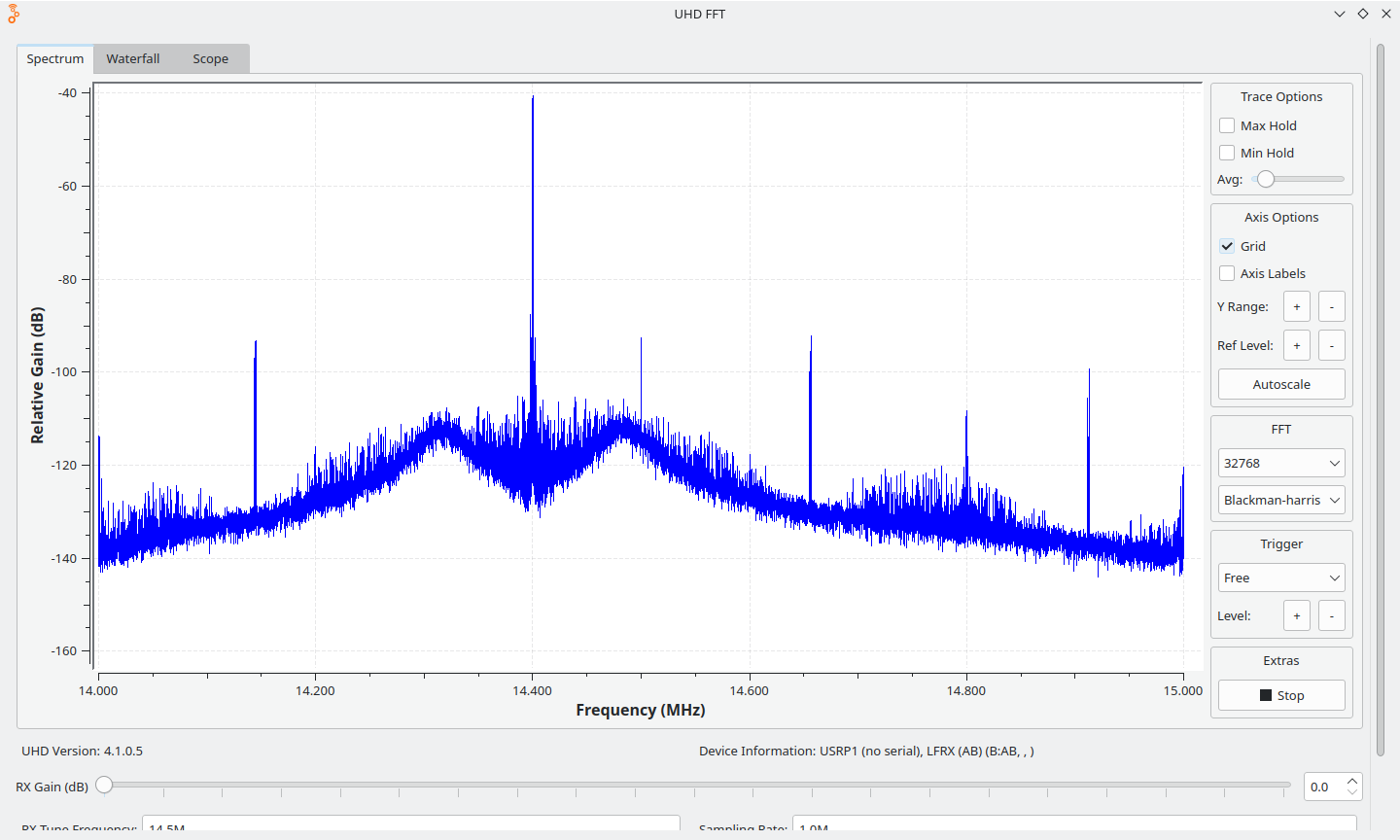
at 14.4MHz
signal -41
imd peak -87 (-46)
sample rate spur -92 (-51)
the 14.5MHz spike is a DC offset artifact in the USRP, not from the P2.
I think this meets the requirements for at least a low power ham transmitter, with LPF of course. There is a tone in the audio passband that matches the weaver frequency. I'll need to look into that.
Comments
I feel your pain. I have been working on a SSB ham transceiver for about 2-Years. The first iteration using the P1, I just plain ran out of memory.
The next generation transceiver using the P2 is much better, and I have written most of the software & a it is looking good, with lots of options (feature creep included.) The receiver and transmitter circuits, and sub-circuits are pretty much worked out, stable, proven and tested. II am using the Silicone Labs ( now SkyWorks ) Si570 Numerical Controlled Oscillator, NCO, synth chip. It is very stable, no spurs, and covers all the frequencies I need.
The next BIG problem is component parts. Good luck with that. I recently combed thru my Bill of Material build list. So many of the individual component parts have gone End of Life, or just Discontinued for any number of reasons. This includes my oscillator IC, mixer chips, common connectors, switches, relays and other first level parts, with no easy replacements. Add to that, I refuse to buy any electrical component parts from CHINA, and even if I did the prices have gone up at least 25-percent in the past year... My feeling is that Taiwan will be invaded in the next few years, and will cut the US off of everything: electric components, cell phones, laptops, clothing, appliances, toys,,, everything... How is a business to plan for anything like this??? End of rant.
@SaucySoliton Does this mean we could build a WSPR beacon transmitter with just a P2?
Sure. People do it with a Raspberry Pi. The Pi's fractional clock divider isn't even that clean.
Since WSPR is frequency modulated it would be best to not use this SSB modulator. Just frequency modulate the DDS.
Here's an incomplete project for the si5351 https://hackaday.com/2021/04/15/the-50-ham-a-simple-wspr-beacon/
Hmm... I doubt it can be 'just a P2' as the P2 PLL is not fine enough, or maybe not stable enough ? There are also absolute time and ppm calibrate questions, suggesting a P2 + GPS as minimum ?
What might work is a P2 with a good VCTCXO oscillator, using a P2 DAC pin to voltage control the master clock to the few-ppm shifts needed and having the P2 PLL simply follow that, with a high PFD.
That would not support all possible channels.
Info is here
https://en.wikipedia.org/wiki/WSPR_(amateur_radio_software)
Google finds some use Pi + AD9850 DDS chip, others use Pi + Si570 Clock Synthesizer (mentioned above), and some even mention Si5351A.*
GITHUB has this https://github.com/JamesP6000/WsprryPi
This hints that the Pi PLL can be groked to be 'good enough' ?
Credits goes to
Oliver Mattos and Oskar Weigl who implemented PiFM [1] based on the idea of exploiting RPi DPLL as FM transmitter.
Dan MD1CLV combined this effort with WSPR encoding algorithm from F8CHK, resulting in WsprryPi a WSPR beacon for LF and MF bands.
Guido PE1NNZ pe1nnz@amsat.org extended this effort with DMA based PWM modulation of fractional divider that was part of PiFM, allowing to operate the WSPR beacon also on HF and VHF bands. In addition time-synchronisation and double amount of power output was implemented.
James Peroulas james@peroulas.com added several command line options, a makefile, improved frequency generation precision so as to be able to precisely generate a tone at a fraction of a Hz, and added a self calibration feature where the code attempts to derrive frequency calibration information from an installed NTP deamon. Furthermore, the TX length of the WSPR symbols is more precise and does not vary based on system load or PWM clock frequency.
Michael Tatarinov for adding a patch to get PPM info directly from the kernel.
Retzler András (HA7ILM) for the massive changes that were required to incorporate the mailbox code so that the RPi2 and RPi3 could be supported
Addit: those working with Si5351A seem to favour the TCXO based module : https://etherkit.github.io/si5351abb_landing_page
@PropGuy2 - out of curiosity - what programming languages have you used to create your P2 SSB transceiver? Just assembler?
Cheers, Bob
@bob_g4bby - I use Spin2 Tool version 2.9.2 - along with ANSI VGA Terminal driver v1.0 / 9-15-2020 by Eric R Smith. Using the 50 x 18 screen tiles and the P1 /P2 type font. for readability, etc.
The code for the VGA screen, rotary encoder VFO knob, and input Keypad - is deceptively simple, and anyone could do it. The math registers for the Numerically Controlled Oscillator ( NCO,) Si-570 synth chip, not so much. The Silicon Labs (now SkyWorks ), is in question right now. Like wise for a good RF / IF mixer chip... Most of the component parts come from CHINA, and that is a problem for me...
Terry, why would you like to do that ? Because of the "one chip" solution ?
The P2 DDS has a 31 bit tuning word. At 320MHz clock, that is a 0.149Hz tuning step.
The P2 PLL's phase noise isn't so good. But it might be good enough for HF. That is easily remedied by using an external 80-125MHz crystal oscillator and leaving the PLL off.
GPS would be handy for time synchronization and frequency calibration. Or WWVB.
That's an average number.
The P2 is wholly digital, so if we take a 250MHz clock to 3.5926MHz, that needs to average = 278.3499415ns periods.
However, P2 cannot do that directly, it has to jitter between whole SysCLK numbers, to give an average that is close.
70/250M = 280ns and 69/250M = 276ns, which is about 52kHz of spread. I'm not sure how the receivers would cope with that.
The DDS mode samples a sine wave with a phase accumulator, and will thus (rounding error and analog funny business notwithstanding) generate precise frequencies all the way up to it's nyquist limit (sysclk/2).
Yes.
Sorry for the dumb question but what is the purpose of a WSPR transmitter? I looked that up on wikipedia but they don't tell either. I mean, does it have any practical application or is it just for fun? With 6Hz bandwidth and 1.4Bd the data rate is below what you can do with a manual morse code transmission.
It's fun, yes, but most importantly, it lets you, and others too, evaluate the EM wave propagation conditions between given locations. The transmitters are just part of the chain (transmitters, receivers, web service to view the reported received locations). That's how I see it.
I think the P2 could also be used for "real" RF applications like remote controls or voice radios ranging from walkie talkies (27MHz FM) to aviation (~120MHz AM). The P2 can generate the IF signals with 455kHz or 10.7MHz. Then we need a mixer and RF amplifier as external components.
Unfortunatelly, I don't know much about the current components. When I was a child I played around with spy bugs and remote controls but at that time everything was discrete and analogue.
Maybe we can fall back to the all-analogue circuits if those RF chips are no longer available.
A fellow amateur radio friend of mine Ron, G4GXO, uses a DSPIC with dual processors running at 70MHz clock rate to do a software defined transceiver for SSB, AM, etc. in the range 3.5 - 30MHz. One processor does all the dsp, whilst the other handles tuning and front panel interface. I'm fairly convinced the P2 would be higher performant than the DSPIC. The sort of external components needed are - bus switches used as double balanced Tayloe mixers, an SI5351 for local oscillator, low noise opamps, two low noise a/d converters (hifi grade) for the receiver front end. I suspect a smartpin a/d would do for mic in and smartpin d/a for speakers out as the signal levels are much higher than the receiver input. Most of the RF components are things like low pass filters and some mosfets for the transmitter power amplifer. Such radios quite often deliver say 5W PEP to the antenna socket, so the output stage doesn't need to be much. An external linear amplifier is used to boost output to a more useful level. I run 100W most of the time with either a Hermes Lite or Multus Proficio sdr. (Both these use a PC for the DSP backend, though)
I believe Ron programs exclusively in C and he's found it runs fast enough, even for the dsp side of things. His radios are truly self contained - no PC backend.
This series of articles is still valid for 1st generation sdr designs and gives you some idea of the parts required.
Cheers, Bob G4BBY
@ManAtWork The other application for WSPR is Amateur Radio High Altitude Ballooning (ARHAB). It allows for tracking payloads out of reach of a VHF Automatic Position Reporting System (APRS) iGates.
Does that also help prevent the gov't from shooting down your balloon?
LOL, No. Apparently not.
If I understood it correctly the Tayloe or multiphase switching mixer needs a 4:1 multiplexer running at 4 times the local oscillator frequency. So I guess the 30MHz limit comes from the max. switching frequency of 120MHz. So if I need >100MHz RF it would take >400MHz switching frequency which is not practical. Also, for the transmitter I'd need an upward mixer which is not possible with the Tayloe circuit, AFAIK.
Edit: OK, I've found the data sheet of the AD8343 mixer chip. The "circuit description" chapter there describes the working principle quite well. The x4 switching frequency is not really necessary, a complementary design with 180° phase shift (inverter) is sufficient. The mixer can be used both for up- and downward mixing if the frequencies are choosen such that the unavoidable harmonics of the LO frequency are out-of-band of the filters.
Fundamental to any radio that uses the P2 as part of the signal path will be proving the dsp required is correct and working. This might best be written in assembler (or maybe C?), working on buffers of IQ data streaming in from the receiver front end. I had started on this by building a test harness between a P2-EVAL and a PC. The PC ran a small Labview based application, the P2-EVAL ran dsp words under Taqoz forth. This was very quick to edit and test. The signal path was:-
1. Labview signal generator creates a buffer's worth of signal and sends that to the P2 as binary data over the USB serial link
2. Serial input into Taqoz, storing it in a local buffer
3. Repeat for another signal if required
4. Assembler DSP function called under Taqoz, result stored in one of the input buffers
5. Serial output from Taqoz, back to the PC
6. Labview program receives result and displays both inputs and output in a graph
With a 921600 baud USB link, this wasn't a real-time set up, but was fast enough for debugging via graphs and other analysis of the returned data. I didn't get too far with this - tested out an 'IQ modulator' function OK - but found learning the instruction set to be slow work. The Parallax technical documentation particularly for assembler has improved since I last had a go, of course, but is still not 100% there.
This was my IQ modulator code for example operating on 16 bit signed data:-
code MYDSP      ( BUFA BUFB size -- )
    mov r2,PTRB
    mov PTRA,c
    mov PTRB,b
    FOR:
        rdlong xx,ptra++            --- xx = a
        rdlong yy,ptra--            --- yy = ib
        rdlong r3,ptrb++            --- r3 = c
        rdlong r4,ptrb--            --- r4 = id
        muls xx,r3                  --- xx = ac
        muls yy,r4                  --- yy = bd
        adds xx,yy                  --- xx = ac+bd - real part of result
        mov zz,xx                   --- zz = ac+bd - real part of result
        rdlong xx,ptra++            --- xx = a
        rdlong yy,ptra--            --- yy = ib
        muls xx,r4                  --- xx = ad
        muls yy,r3                  --- yy = bc
        adds xx,yy                  --- xx = bc+ad - the imaginary part of result
        wrlong zz,ptra++
        wrlong xx,ptra++            --- save result in BUFA
        add PTRB,#8                 --- point to next value in BUFB
    NEXT: a
    mov PTRB,r2
    jmp #@3DROP
end
I notice @Reinhard is writing IQ dsp in C, would that be a better way to go with the chance of reusing existing dsp C libraries maybe? What's the speed penalty?
Some hams have fed the two SI5351 outputs directly to the mixer. The two 'oscillators' inside the SI5351 can be set to the same frequency but offset from one another by '90 degrees'. I haven't found any comment on how precise that is, though. It possibly raises the maximum working frequency to the 120MHz-ish region. Stray C and L would make the layout ticklish, though. Much safer to make a tunable 30MHz transceiver that runs into a simple transverter to get to the wanted VHF or higher band, as has been done for many decades.
If xx is directly after zz, yy after xx and r4 after r3 then quite a few cycles could be saved by using Fast Block Moves (see doc). E.g. reading yy or r4 or writing xx would take only one cycle (plus two for
setq) instead of nine and pushing & popping xx & yy would be faster than reading them again.FOR: setq #2-1 rdlong xx,ptra --- xx = a, yy = ib setq #2-1 rdlong r3,ptrb++ --- r3 = c, r4 = id, point to next value in BUFB push yy push xx muls xx,r3 --- xx = ac muls yy,r4 --- yy = bd adds xx,yy --- xx = ac+bd - real part of result mov zz,xx --- zz = ac+bd - real part of result pop xx --- xx = a pop yy --- yy = ib muls xx,r4 --- xx = ad muls yy,r3 --- yy = bc adds xx,yy --- xx = bc+ad - the imaginary part of result setq #2-1 wrlong zz,ptra++ --- save result in BUFA NEXT: aThe in-band spurious emission seen in post 1 might not be real. I discovered today while testing AM mode, that I was seeing what looked like ~1khz AM modulation even on a continuous carrier wave. Placing my finger on the P2's crystal loads it enough to audibly shift the tone. Now I was using 256MHz for the P2 clock rate, and my SDR has an unfiltered ADC running at 64MSPS. No filters on either the P2 or the SDR. There might be something weird happening with the image frequencies.
Even though AM isn't power efficient, I think it's good to have just for completeness or for interoperability with other radios.
I developed a technique to get better than 8 bit amplitude resolution in DDS mode. A quadrature modulator like I used originally has more than 8 bits of amplitude control. For example, transmitting (1,1) has a vector magnitude of sqrt(2) or 1.414. A convenient level between (1,0) and (2,0). What is not so great about this scheme is that (1,1) has a 45 degree phase shift compared to (2,0). Ideally, any scheme to increase the amplitude resolution should 1. not add unwanted phase shifts to the signal, and 2. be computationally efficient.
Instead of generating a look up table with sine and cosine, I made the table with two sine wave of varied amplitudes. I still use the third DAC channel to center the signal at Vcc/2. I used 126.05 and 7.47 for the amplitude, although I don't claim those to be optimal. The second table has an amplitude about 1/16 that of the main. The 7 most significant bits go to scaling the main output signal. Then an extra 4 bits goes to scaling the second table. The peak to peak amplitude is unaffected due to the quantization. The second DAC channel adds a little bit more and "fills in" the sine wave and increases the RMS value. There are some missing codes in the output, but like ADC window filters, this is a game of averages. Reducing the average quantization noise improves the signal even if there is an occasional large step. Perhaps this could go to the next level using 2 DAC pins in a unequal weighted fashion to get finer resolution.
What I give up is the quadrature modulator. It can still generate an SSB signal by separating it into phase and magnitude components. This is reasonable as a cutting edge ham transmitter would be routing these components to separate places, rather than getting a fully formed SSB signal right out of the P2 DAC. The phase/frequency component goes to a non-linear amplifier. The magnitude component is used to modulate the supply to the amplifier, which will vary the output power. If both of these components can be varied at a few kHz rate, then an SSB signal can be formed at a high power level. The uSDX folks are doing this on an ATMega328. I was going to do this on an STM32F103 a long time ago, but didn't quite know how to get everything done back then. Using the P2 cordic for atan2 is sweet.
I did some tests to look for glitches using the colorspace converter as a signal modulator. It looks clean. The DAC output changes as expected after a few clock cycles delay.
@TonyB_ , many thanks for the code speed-up. It got me rethinking about sdrs on microcontrollers:-
1. The signal path is most probably a series of small loops operating on buffers. If those are written in assembler, then you have the opportunity to reduce instructions like you show. The current C compilers will be far more verbose, so forget C. If the loops are already small, then any reduction in instruction count makes quite a big difference that could make time for more features
2. A beginner can produce working assembler code almost immediately, but the P2 has a lot to offer which is easily overlooked - only experience and this forum brings that out. Literature on fast P2 technique doesn't exist yet other than scraps lost embedded within the forum. We could do with that famous book "High speed DSP on the P2"
3. PC based sdrs are feature rich with spectrum and waterfall displays, noise reduction, multi-width filtration - many bells and whistles, in no way limited by the platform
4. So any SDR on a microcontroller is always going to end up filling available space and time - it's a quart into a pint pot
5. The P2 is a unique space to fill - 8 cores, cordic, private and shared memory, 300MHz - so developing the code in a way that it can be easily redistributed around in that space leaves options open when things get tight in a particular spot. Small, linked subroutines written like forth, dare I say
6. Maybe one core for controls and external data links, Maybe one for graphics controller, leaves six cores and the cordic for signal path. Six cores sounds a lot, but I bet it isn't eventually. How to get those six cores handing off the data to one another in the time available? How to run the cordic for minimal waits? What size buffers and signal sample to use? (The cordic engine may dictate the latter)
@SaucySoliton - the uSDX is maybe the ultimate example of getting a lot out of a tiny platform. It's prompted my pal Ron to have a go at '4th method' SSB generation too. His first application is for cave exploration, the radios run at VLF to penetrate limestone to a degree. Having a Class D power amplifier instead of AB would be a big battery saver, where the radios are needed to work for a long time on one charge. They're used for communication, but also for surveying the cave system, surface <-> underground.
Is the uSDX algorithm the best for the P2 or are any of the alternative ways for processing SSB, AM etc possible or a better fit? e.g. I've heard the SSB produced by a uSDX and it sounds relatively harsh compared to PC based sdrs. Is that because of the tiny arduino, or is it a given with '4th method' SSB? Even with the P2, not all algorithms may fit in the space and time and only trying it would reveal which. e.g. Testing an IQ fft would reveal whether that runs fast enough to be useful would rule quite a few algorithms in or out.
I'm happy to help whenever I can. The fastest way to execute a block of instructions in cog/LUT RAM multiple times is to use
repbecause the jumps back to the start of the block take zero cycles. I think the following could replace FOR: and NEXT:' FOR: rep @.end,a setq #2-1 rdlong xx,ptra --- xx = a, yy = ib setq #2-1 rdlong r3,ptrb++ --- r3 = c, r4 = id, point to next value in BUFB push yy push xx muls xx,r3 --- xx = ac muls yy,r4 --- yy = bd adds xx,yy --- xx = ac+bd - real part of result mov zz,xx --- zz = ac+bd - real part of result pop xx --- xx = a pop yy --- yy = ib muls xx,r4 --- xx = ad muls yy,r3 --- yy = bc adds xx,yy --- xx = bc+ad - the imaginary part of result setq #2-1 wrlong zz,ptra++ --- save result in BUFA .end ' NEXT: arepis described in the doc in the Instruction Repeating section. Interrupts are ignored duringrepblocks, which may be irrelevant here. Addingrepwith a repeat count of one is the easiest way to stop time-critical code from being interrupted asrepdoesn't change the state of interrupts - if they were allowed/stalled beforehand the same will apply afterwards.I have been wanting to build a WWV receiver so I can calibrate timers and other test instruments.
@bob_g4bby I think the uSDX is limited by the ATMega processor. Here is a high performance polar SSB transmitter project. https://www.polex-tech.com/polex-pdf It uses amplitude and phase correction to improve the signal purity. Not sure why it's a transmitter only. It would be easy to hide a Tayloe detector receiver in there. The P2 could run the RX and TX at the same time.
Just to play a round of code golf:
'    FOR:

        rep @.end,a
        setq #2-1
        rdlong xx, ptra              --- xx = a, yy = ib
        setq #2-1
        rdlong r3, ptrb++            --- r3 = c, r4 = id, point to next value in BUFB
        altr zz
        muls xx, r3                  --- zz = ac
        altr temp
        muls yy, r4                  --- temp = bd
        adds zz, temp                --- zz = ac+bd - real part of result
        muls xx, r4                  --- xx = ad
        muls yy, r3                  --- yy = bc
        adds xx, yy                  --- xx = bc+ad - the imaginary part of result
        setq #2-1
        wrlong zz, ptra++            --- save result in BUFA
 .end

'    NEXT: a
Redirecting the output of the first set of multiplications saves having to push and pop the parameters. All up saves three instructions (6 cycles) per loop, and costs one extra long of temp storage.
Nice one @AJL , anything to reduce the loop size is useful as the loop count could be anywhere between 64 - 2048 depending on application. Reminds me of the code ping-pong myself and Doug Seaton at Ferranti's played, sweating the bytes out of a fast 'straight line' algorithm for graphics. Z80 assembly language back in the 80's - we evolved a surprising speed-up.
What do folks interested in P2 sdr consider the 'best fit' sample size for IQ maths? The first generation PC based sdrs were based on 16 bit stereo sound cards. Nowadays 24 bit a/ds are cheaply available from ebay and the like, although it's not clear to me how many useful bits they deliver. The modulator code above is 16 bit - is that the best? I note the cordic engine works with larger integers / fixed point floats, although that doesn't stop you feeding it with 16 bit data. What maths precision are you using, @SaucySoliton ? I guess the choices are 16, 24 or 32 bit.
Another aspect I'm not familiar with is integer dsp. I've modified and extended several PC based sdr programs, but those were floating point, internally. Any advice on useful reference books or papers for integer radio dsp?
My shot again. I've never used
altruntil today.zzcan be anywhere and no need fortemp, saving two cycles per loop and two longs:rep @.end,a setq #2-1 rdlong xx, ptra --- xx = a, yy = ib setq #2-1 rdlong r3, ptrb++ --- r3 = c, r4 = id, point to next value in BUFB altr zz muls yy, r4 --- zz = bd muls r4, xx --- r4 = ad muls xx, r3 --- xx = ac muls yy, r3 --- yy = bc adds xx, zz --- xx = ac+bd - real part of result adds yy, r4 --- yy = bc+ad - the imaginary part of result setq #2-1 wrlong xx, ptra++ --- save result in BUFA .endEDIT:
The time taken for each loop is dominated by the three hub RAM accesses and length of these depends on the difference between the current hub RAM or egg beater slice and the read/write start address. Time savings for other instructions on paper might not happen in practice. Reading and writing multiple samples would be more efficient and if I knew the values of BUFA and BUFB I could come up with more optimal code.