

P2 Maxi Breakout Board
 VonSzarvas
Posts: 3,639
VonSzarvas
Posts: 3,639
in Propeller 2
This larger breakout board idea was shown at the last P2LF. Since then...
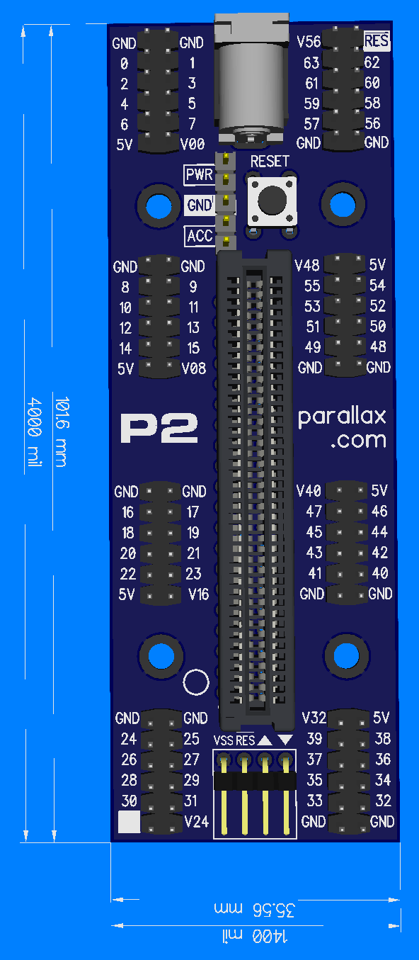
- It got a little shorter (was 114mm, now 102mm).
- PWR pins added (board will be shipped with 2 shunts installed on the PWR and ACC positions).
Pwr header notes:
- Removing the ACC shunt disables power to the 5V accessory headers
- Removing the PWR shunt disables power to the breakout.
- Remove shunt to inject own power at the PWR/GND header, instead of using DC Barrel Jack.
- Replace shunt with a remote switch at the PWR header and/or ACC header pins.
Observations:
Reset button is close to the pwr/acc header as it needs to clear addon boards. Trying to add the extra feature without increasing board size/cost.
Edge module will be inserted with components to the left (ie. opposite way to the mini breakout). Plan B would be to have the Edge the same orientation as mini, but reverse the order of the accessory headers, such that V56 would be bottom-left instead of top-right.
Comments
Looks really good
Is there room to rotate the 5 pin header 90 degrees, and move the reset button to near the prop plug header,enabling the card edge connector to be more vertically centred?
I like this! Great footprint for doing development that is just video and HID.
If the pcb is about 3mm wider. At the moment it matches the mini width. Not essential to keep that dimension, but nice.
Other pro for this configuration...
Here's an earlier render that didn't quite fit.
Possible to go this route by increasing width to 1500mil.
Ok I see what you mean
Would a 2x3 header (instead of 1x5) let you keep the same 1400 width?
Labeling space.
Anyway.. you prefer that reset button near the propplug header config by the sounds of it ? Thats good to have opinions.
I have a 2x3 version too. Can't recall just now what were the issues. I think it was only silk and some manufacturability reasons. Probaby they needed a space to ensure a header couldn't be installed on the wrong axis- kaboom. Will re-visit.
I don't really mind where the reset button is, so long as its there somewhere. It was more that it lets the edge module be more central rather than offset.
And yes these are mere opinions, any of these renders translated into a real product would be super useful
Central... Is that for aesthetic or practial reasons?
@VonSzarvas I like your original design because it will mount well on a wall with the power cord going down to a wall outlet. Also, with the 1x5 header across the [width of the] board any aux power lines can flow over the top of the 5V socket and down the wall as well. I like the reset button close to the prop plug. That way after programming the board I can pull the plug and reset the board. My only major suggestion is rotating the labels 180 degrees. That way with the power at the bottom and the prop plug at the top you can read the labels correctly. Also, as long as the distance between the add-on board pins and the P2 socket are the same or a little wider my P2 cover will fit with any add-on boards.")
(aesthetic reasons!)
Good") All pins available now.
All pins available now.
Sometimes centralizing can also help to fit boards inside symmetric enclosures, rather than requiring special offsets for cut outs etc. Also eases stress a little by spreading the insertion force over all four mounting points evenly.
A smaller 2 pin reset switch may help if it's still a bit too tight next to the prop plug.
Change 5V_Common label to V_In. The main reason for the jumpers is to separate 5V_Acc from the 12 Volts that could be on both DC_Jack and V_In.
Here's the latest image- all routed in today.
For custom use... The power header pin order would accept an xx1117 range regulator for the ACC-HDR feed. So the header could be removed to fit the regulator, or just solder the regulator on the back of the PCB, along with in/out SMT caps. Or save the soldering, and just use jumper wires to an off-board supply for either the pwr feed, acc-hdr feed, or both. Lots of options.
By default, these will ship with the headers and shunts installed, as otherwise the manufacturing process would be a nightmare if we leave those headers unsoldered. So the recommended DC Jack voltage supply remains at 5V for simplicity, but advanced users have the options to mess about! Officially this header is only to allow power on/off control for the accessory pins and main power, but removing the shunts and injecting power is now very simple, and perhaps very handy in a tight enclosure. The pinout ensures nothing bad happens if the shunt/s are connected the wrong way.
Next up...
Time to sort out the silk screen.
CJMJ mentioned 180 degrees... that's long been my preference too as it means the add-on labelling could always align when connected from any angle. Of course, that ship has sailed for now, but maybe it wouldn't hurt to get the ball rolling on a gradual transition to 180 degrees. Some things to consider after the NYr merriment!
Edit- gosh, that's a back-to-the-future moment! 2020 all over again!!
Nice one @VonSzarvas . Am liking the header options available. Plus having that spare ground in the 2x3 header would be handy for grounding a scope probe if all accessory slots and a prop plug is connected.
I agree, great solution.
What would be nice is the ability to run it completely off a phone when using low power peripherals (or none). A raspberry pi pico can be used for the USB serial(has anyone implemented a proplug pico yet) & power interface until too much current is needed. Then a separate USB-C (because almost everybody already has USB-C power supplies) input power could be used on the P2 board and then it could power the phone.
Hear what you're saying. As another alternative I typically use the USB to DC Jack cable to power the board, either from a laptop usb port, hub, or from a small power-bank.
Doesn't get much simpler than that, and keeps the cost as low as possible for everyone (vs. the convenient but more expensive USB-C.).
I'd like to see some of the boards with FTDI built in moving to USB-C in the near future though.
Why not fit for these?
https://www.tindie.com/products/invector/challenger-rp2040-mstk/
Then you get an RP2040, which would have to be programmed to store and boot the P2, but you also get battery connection too. The blank space on the top means that you can surface mount underneate, or upside down on top. I hate paying for FTDI chips, which are pretty simple. The RP2040 is WAY more capable for about the same price as an FTDI module.
USB itself, is far from simple.
The RP2040 is an awesome companion for the Props. The Picomite BASIC just keeps on getting better. Now it has VGA support and a filing system for the extra flash.
I don't use the Pico because it only has 2MB flash. Mine have 8MB and I now have some 16MB on the way.
Propeller resources are precious, I refuse to waste them.
Hi
@Mickster
Would you mind telling me where you get boards at that price shown ie £2.27 for 16MB.
Thanks
Dave
Right here (need to select the flash option):
https://a.aliexpress.com/_mPnDHXC
Did you get the purple one? Amazing price. Any idea how much power can be put through them @5V and @3.3V?
Hi
Ah yes- I've had mixed results dealing through aliexpress.
great prices and fast when the tansaction works- but hit a brick wall when it fails.
Depends on individual seller I guess.
Ebay always good so far but more expensive and longer delivery times.
Thanks
Dave
please do NOT make the mistake again attaching a FTDI to each board. Please.
PropPlugs are easy and can be removed to use the pins without FTDI from other MCs.
Parallax did the move after the P1 Project board and it is a PITA to cut out or de-solder the FTDI on most parallax boards.
USB-C is not convenient, it is a pain. The connectors rip off easy, P2-Edge can handle more the 5V anyways and it is more expensive on top of it.
By the way is there any way to access the missing 2 pins on the mini-breakout to have 42 IO on the P2-Edge 32MB instead of just 40?
Mike
Yes, those are all included in the reasons we don't include FTDI on these boards, and also don't use USB-C on breakout boards.
For the 2-pins... the mini breakout has a protoboard area. Solder a header onto that, and solder jumper wires on the bottom of the PCB from the header to the required IO pins directly on the edge socket. The spare IOs are circled, and the pinout diagram is included with the Parallax Shop mini-breakout product page resources.
cool, did not see that. Combined with the RAM Edge the mini Breakout is perfect.
Another question @VonSzarvas, any plans on a new batch of Spineret's? Such a wonderful board but I run out of stock, just 4 or 5 left. Only thing to change would be the bigger Version of the Wiznet chip with more parallel connections, but as is already perfect.
Powered with the DB power square thing a unbeatable small webserver.
@"Mike G" (I think) and me wrote some nice firmware each and then Parallax stopped production.
just interested in some more of them.
Mike
I have several flavours of RP2040 modules from AE and I immediately overclock them to 378MHz. Not a single problem whereas I've had RPi Picos that can't handle 250MHz....go figure
Craig