

QuickByte Simple Video Driver – Using Images
 kg1
Posts: 164
kg1
Posts: 164
P2 QuickByte: https://parallax.com/p2-simple-video-driver-using-images-intro-to-using-video-2-of-3/
Download: "P2 Image Format Code": https://parallax.com/package/p2-image-format-code/
If using HyperRam Download: rogloh hyper.zip
Add two files: hyperdrv.spin2 and hyperram.spin2 to "P2 Image Format Code" folder
Hardware:
Display: https://www.parallax.com/product/7-hdmi-display-800-x-480/
Board: https://parallax.com/product/propeller-2-evaluation-board-rev-c/
HyperRam: https://parallax.com/product/p2-es-eval-board-hyperram-hyperflash-add-on/
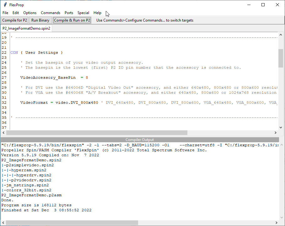
Current settings:
in p2simplevideo.spin2
line 55 mem : "hyperram"
line 105 BPP := 32
in P2_ImageFormatDemo.spin2
line 34 VideoAccessory_BasePin = 8
line39 VideoFormat = video#DVI_800x480
in hyperram.spin2
line 42 DATABUS = 32
Thank you to: @VonSzarvas @evanh @rogloh
Comments
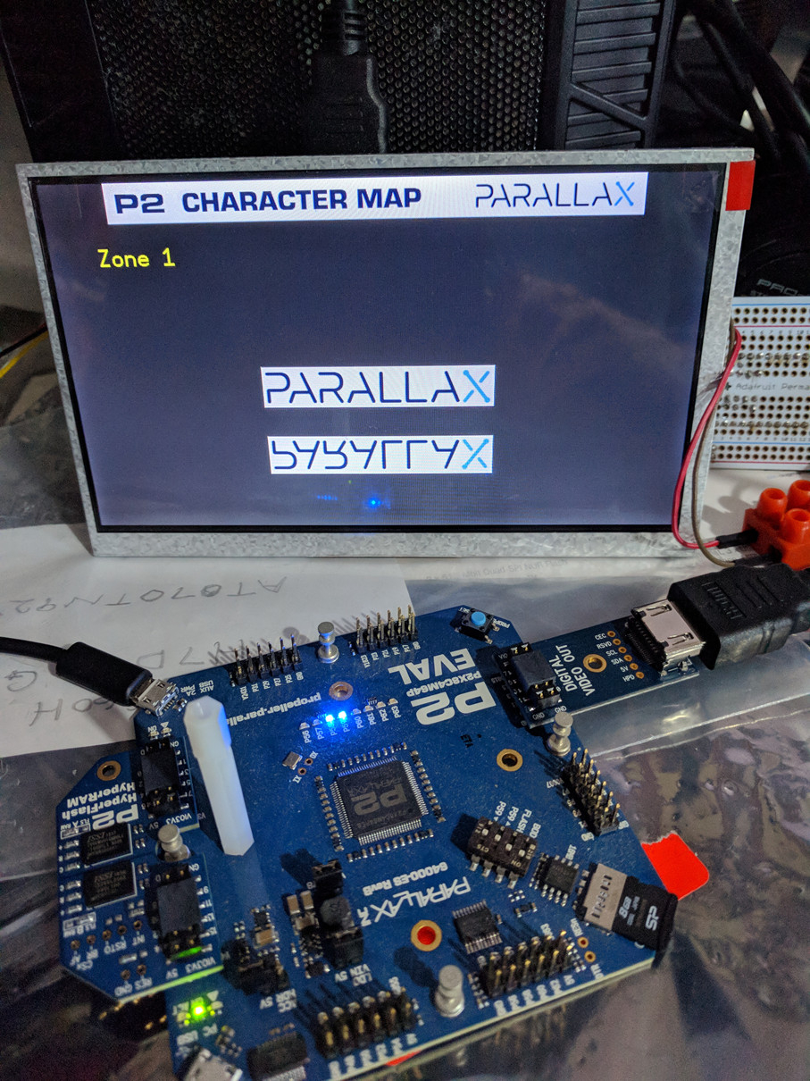
@VonSzarvas Lets use the new hardware!
Current settings:
in p2simplevideo.spin2
line 55 mem : "psram"
line 105 BPP := 32
in P2_ImageFormatDemo.spin2
line 27 VideoAccessory_BasePin = 8
line32 VideoFormat = video#DVI_800x480
in psram.spin2
line 41 DATABUS = 40
What product is most likely to fail in time of disaster? Cellphone?
@VonSzarvas Using the code above and only one graphics file: Debt in US 8 bit.bmp size: 234KB
Could you please comment on how I might improve the display output?
Looks like the width of the BMP must be a multiple of 4 to show right, so make it 696 instead of 697 pixels wide.
I don't know why.
Andy
@Ariba Thank you Andy.
Changed the file type: "Image format code_20221207_small.png"
Kevin
Thanks Andy, yes that's the quick fix.
I remember hitting that hurdle too, whilst adding the wrapper, and I added some offset adjustments in the code wrapper to resolve it. I wonder if the "image flip" attribute of video.LoadImage makes a difference to how that automatic handling of non-even dimensions works. That flip feature was added much later and I may not have gone back to test different image widths. With the flipped image, the reference/origin point may have shifted meaning we need to offset another direction. Hmm. Or maybe it's something else entirely! Will take a look once I clear some backlog from being away a few days.
Very nice to see the new hardware @kg1 !
One thing... during operation, maybe best to keep the boards off the slightly-conductive metallic anti-static bags. Could introduce some signal oddness that delays your experiments (or worst case part fatigue/failure, especially in case of power rails being slightly shunted).
From Wikipedia (about the BMP format):
"Each row in the Pixel array is padded to a multiple of 4 bytes in size"
So all you need to do is change this line in LoadImage():
to:
and it should work with any pixel width.
I have tried it with kg1's image and it works, I have also removed this 'shift correction' for uneven pixel sizes.
Andy
Thanks @Ariba. That's a great help. Will get that updated in the QB sources.
Michael
I only have a single PSRAM chip on my own board. This is not fast enough for 32bit pixels, so I have modified the simple video driver to work also with 8 and 16 bit wide pixels. The color conversion happens on the fly, while loading pictures or drawing graphics, so the colors are defined always in 32bit RGBA.
Attached is the modified driver. The pixel size is now passed from the main object to the driver, and no longer hardcoded in the driver. For that add BPP_8, BPP_16 or BPP_32 to the 'videoFormat parameter, i.e.:
32bits is the default if you don't add any BPP_x, so it should be compatible to the examples.
The 8 bit mode uses the RGB 3:3:2 format of the P2, I was surprised how well the pictures look also in this low resolution (for example the SolarPanel monitor).
Be aware: The driver is only tested with the examples from the QB, and only with the psram4 memory driver, no guarantee that anything works.
Andy
That's neat. Thanks for that.")
Initial thought is if that would impact text overlay / transparency ? I guess not as the colors are still 32-bit.
I'll try a few combinations to experiment
@VonSzarvas @evanh @rogloh @Ariba
I have purchased a new display: https://buydisplay.com/7-hdmi-lcd-module-display-touchscreen-vga-video-driver-board
It has capacitive touch with USB interface: https://buydisplay.com/download/manual/ER-TPC070-8-USB_Drawing.pdf
But no datasheet. Is there any SPIN2 code I could study? How might I view the touch data via USB interface?
You'd probably want to try out the USB driver from garryj (there's also modified versions around more recently updated by Wuerfel_21 and/or macca but that's mainly for USB joystick/gamepad controllers IIRC).
You'll need to hope this touchscreen controller emulates a standard type of USB mouse, otherwise you'll be needing to write your own driver (or modify the USB one) and for that you'd have gather all the information required to interface to this controller and learn lots about USB operation which no doubt will be very involved and complicated. Alternatively you might be able to have the P2 talk to it directly via i2c and bypass your ER-TPC070-8-USB board (I think it's probably using a GT911 controller). A little easier perhaps but still not particularly easy unless you understand the GT911 registers that need to be accessed and their setup order etc.
Start here:
https://forums.parallax.com/discussion/170149/p2-hosted-usb-keyboard-mouse/p1
@rogloh Many thanks for your excellent reply.
"Alternatively you might be able to have the P2 talk to it directly via i2c and bypass your ER-TPC070-8-USB board (I think it's probably using a GT911 controller)."
This is most likely the best solution. The GT911 chinese pdf is the best manual but is too large when translated by google to english to show here.
The best google search for USB code is: i2c to usb hid multitouch
Much more reading for me to do!
Kevin
This might be helpful...looks like there is some software done for Arduino which could likely be ported to SPIN2.
http://www.digitaltown.co.uk/components14ESP32GT911Screen.php
I'm somewhat interested in this too as I have a Waveshare LCD which I think may use the same Goodix controller (needs to be confirmed). It'd be nice to hack into that.
@rogloh My ER-TPC070-8-USB is using a HX6518. I can not find a datasheet for this chip. The "Sales Engineer"at BuyDisplay.com said:
"Sorry, the schematic diagram for PCB is unavailable as we couldn't get this file from engineer, Sorry again.
The chip HX6518 is now using on PCB, pls note it.
The touch panel works via USB, there is no need read and store the data, it starts to work after connecting via USB signal.
Any problems, pls make me know."
I also found via a discussion on :
https://forum.arduino.cc/t/i2c-capacitive-touch-panel-to-usb/473020/2
"Write a usb hid driver, use the serial reporting method. Then you have to find the datasheet for goodix 911, the ones you find on the internet are useless because you cannot see the I2C adresses and commands which are necessary to configure the gt911 chipset. What you can do is you can translate the chinese version with google translate "
I found this to be true. If you translate the the chinese pdf above you will have all the technical data which is not in the english version. This is only helpful if you wish to try the I2C direct method which may be necessary to utilize the touch data on the P2?
Interesting.
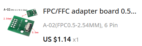
Probably the HX6518 is just some customized microcontroller that adapts from I2C to USB. If the flat flex cable coming out of the LCD has a chip on it that one could be the GT911 and it will present its interface on the 6 pin cable. The simpler adapter board on that video I linked just shows direct connection to I2C and reset etc @3.3V. That's how the guy is getting access to the GT911.
Update: just checked the Waveshare LCD I have and it does contain a GT911
@rogloh I have been searching for:
Delivery will be in February. That is how things run in NZ these days.
In the mean while I will take another look at USB code.
Kevin.
@garryj I have attached a text file which lists input received from an I2C to USB converter (HX6518) into my Windows 10 PC USB Port.
I have no knowledge of USB but hope that within the data flow there is touch screen data. If the structure of the touch screen data is present, I would very much appreciate your guidance and suggestions regarding code I might write to run on a P2 edge to collect data received at the P2 USB port.
Kevin