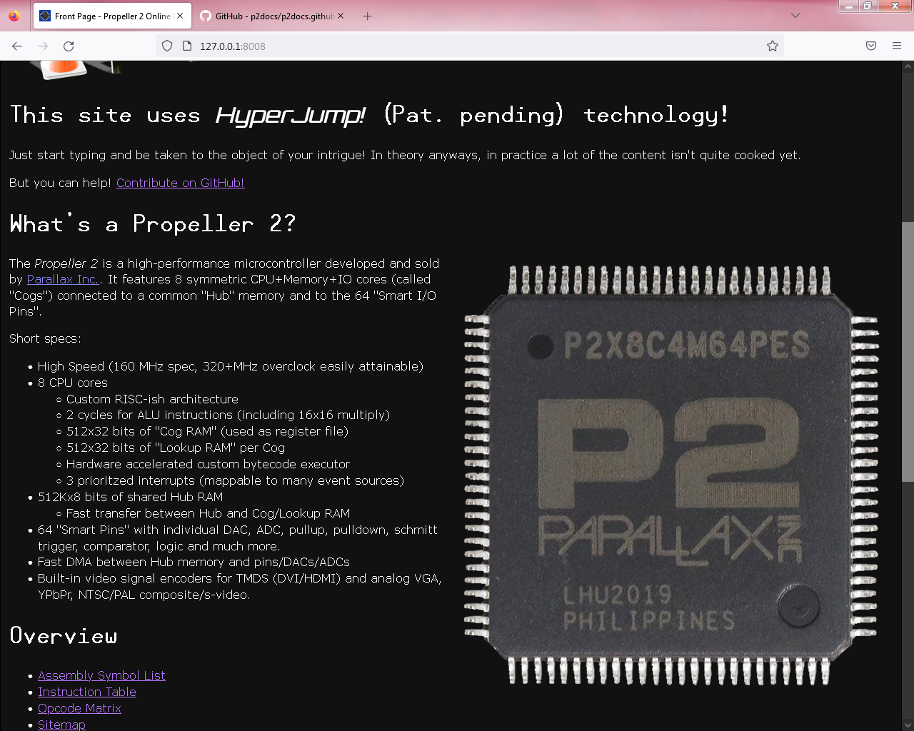
Context: Dark mode (white text on black #111 background). Images with black text look brap no matter what. Leave them as-is and they're either unreadable (if background is transparent) or really ugly (if background is white). CSS can invert the colors, but that's far from ideal for non-greyscale images. Also, images are pain to edit.
BTW, dark support is live now (using media query, so you need to enable it in browser settings (or devtools) to see it)
gather what's available on the P2 docs front plus clarify or refine whatever possible right now
make it super easy and super fast to get to that piece of information you might need that hopefully is already described
fill all the resulting gaps later, when the verified information will become available regardless of the way it was obtained (better description or as experimenting results).
It would not be fair to expect all of our musings to eventually find its way to @Wuerfel_21's documentation project (feature creep).
What constitutes the best documentation perhaps deserves its own thread. I have my idea too.
If there is any interest I'll start one.
@Maciek said:
The way I see @Wuerfel_21's hard work here is to:
gather what's available on the P2 docs front plus clarify or refine whatever possible right now
make it super easy and super fast to get to that piece of information you might need that hopefully is already described
fill all the resulting gaps later, when the verified information will become available regardless of the way it was obtained (better description or as experimenting results).
@ManAtWork said:
It's not only the ordering of the modes and sub modes... Every document so far only repeats Chip's descriptions. But honestly, I don't understand them at all. I mean I understand all the other smart pin modes but not the ones that measure time or count events. The descriptions explain what they physically do but I don't see any reason, intention or purpose in them.
Yes these definitely need good diagrams. Ideally a pertinent diagram for almost every smart pin mode related to timing would be useful. The existing text only explanation is rather hard to read and understand right away in the current form.
Of course. But what actually happens? I think it causes a fast-skip to carry into the call (like how it works for relative jumps), but the details are probably somewhat more complicated.
Absolute address was the only way Chip could get a skip sequences calls to work. Address probably goes haywire if relative.
@evanh said:
@evanh said:
I keep forgetting the details of how "correct sign" works. It's not as simple as bit31 of the result.
Ah, here's the hint in TJV's description:
Dest is a register whose value is tested for overflow (Dest[31] != C).
The name 'correct sign' was one of my suggestions. For signed adds/subtracts/compares C is always the correct sign of the result even if overflow occurs.
TJV D,{#}S is meant for testing and jumping if overflow, however it can also be used to test and jump if D[31] and C are different without doing any prior signed arithmetic.
<%=p2instrinfo('alts')%>
ALTS modifies the next instruction's Source field to be (Source + Destination) & $1FF. Whether the next instruction's Source is an address or an immediate is not affected. Additionally, after the indirection, the signed value in Source[17:9] is summed into Destination.
ALTS' Source can be omitted, in which case it defaults to #0.
<%=p2instrinfo('altd')%>
ALTD modifies the next instruction's Destination field to be (Source + Destination) & $1FF. Whether the next instruction's Source is an address or an immediate is not affected. Additionally, after the indirection, the signed value in Source[17:9] is summed into Destination.
ALTD's Source can be omitted, in which case it defaults to #0.
<%=p2instrinfo('altr')%>
ALTR modifies the next instruction's "Result field" to be (Source + Destination) & $1FF. This allows the result of an instruction to be written to a register other than it's Destination. Additionally, after the indirection, the signed value in Source[17:9] is summed into Destination.
ALTR's Source can be omitted, in which case it defaults to #0.
One thing to clarify here is "field" explicitly means a 9-bit bit-field of the instruction code word. As opposed to "operand" - Which means post-data-fetch 32-bit word entering a port of the ALU.
For example, the XORO32 instruction modifies the next instruction's S operand, not its S field.
<%=p2instrinfo('alts')%>
ALTS inserts (Source + Destination) & $1FF in the pipeline replacing the next instruction's Source field. Whether the next instruction's Source is an address or an immediate is not affected. Additionally, after the indirection, the signed value in Source[17:9] is summed into Destination. The next instruction is not modified in RAM.
ALTS' Source can be omitted, in which case it defaults to #0.
<%=p2instrinfo('altd')%>
ALTD inserts (Source + Destination) & $1FF in the pipeline replacing the next instruction's Destination field. Additionally, after the indirection, the signed value in Source[17:9] is summed into Destination. The next instruction is not modified in RAM.
ALTD's Source can be omitted, in which case it defaults to #0.
<%=p2instrinfo('altr')%>
ALTR inserts (Source + Destination) & $1FF in the pipeline in place of the next instructions "Result field". This allows the result of the next instruction to be written to a register other than it's Destination. Additionally, after the indirection, the signed value in Source[17:9] is summed into Destination. The next instruction is not modified in RAM.
ALTR's Source can be omitted, in which case it defaults to #0.
<%=p2instrinfo('alts')%>
ALTS inserts (Source + Destination) & $1FF into the pipeline in place of the next instruction's Source field (i.e. the given Source address or immediate). The next instruction is not modified in RAM. Additionally, after the indirection, the signed value in Source[17:9] is summed into Destination.
ALTS can be used to index into an Array in Cog Memory, with Source being the base address (and optionally, auto-increment amount) and Destination being the index.
ALTS' Source can be omitted, in which case it defaults to #0.
<%=p2instrinfo('altd')%>
ALTD inserts (Source + Destination) & $1FF into the pipeline in place of the next instruction's Destination field (i.e. the given Destination address or immediate). The next instruction is not modified in RAM. Additionally, after the indirection, the signed value in Source[17:9] is summed into Destination.
ALTD can be used to index into an Array in Cog Memory, with Source being the base address (and optionally, auto-increment amount) and Destination being the index.
ALTD's Source can be omitted, in which case it defaults to #0.
<%=p2instrinfo('altr')%>
ALTR inserts (Source + Destination) & $1FF into the pipeline in place of the next instruction's "Result Field", which is normally always equal to the Destination field. This allows the result of an instruction to be written to a location other than its given Destination. Additionally, after the indirection, the signed value in Source[17:9] is summed into Destination.
ALTR can be used to index into an Array in Cog Memory, with Source being the base address (and optionally, auto-increment amount) and Destination being the index.
ALTR's Source can be omitted, in which case it defaults to #0.
Unrelatedly, if anyone could confer me a transparent PNG of a P2 chip (i.e. without background) or at least a photo on a non-white background, that'd be real swell.
LMAO didn't even notice the markings being different. It looks so similar to the other image that I thought they were the same.
All my chips are -ES, as they were.
Eitherhow, doesn't really matter, I think.
And no, it sucks because the transparency still isn't perfect. If you look closely you might notice that I applied some gaussian blur to the pin areas to make the edges smoother, lol. And that all after a long manual session with the soft erase tool.
That said, in practice it doesn't look like complete ass, so GoodEnough(tm);
Yea, I'm trying to use terms that are perhaps more familiar than the propeller-isms. I would say it's the correct term. It copies between RAM and peripherals. And it also facilitates the all-important external memory transfers.


Comments
Context: Dark mode (white text on black #111 background). Images with black text look brap no matter what. Leave them as-is and they're either unreadable (if background is transparent) or really ugly (if background is white). CSS can invert the colors, but that's far from ideal for non-greyscale images. Also, images are pain to edit.
BTW, dark support is live now (using media query, so you need to enable it in browser settings (or devtools) to see it)
The way I see @Wuerfel_21's hard work here is to:
It would not be fair to expect all of our musings to eventually find its way to @Wuerfel_21's documentation project (feature creep).
What constitutes the best documentation perhaps deserves its own thread. I have my idea too.
If there is any interest I'll start one.
Re-made the eggbeater diagram in HTML. Much smoother and can be more easily edited.
Comparsion vs. GIF: https://p2docs.github.io/diagram_test.html
Fullscreen: http://p2docs.github.io/diagram-eggbeater.html
Yeah, basically that.
New funny detected:
Offical doc has wrong C flag description for ADDS.
I already commented on the google doc, don't worry.
Yes these definitely need good diagrams. Ideally a pertinent diagram for almost every smart pin mode related to timing would be useful. The existing text only explanation is rather hard to read and understand right away in the current form.
It's supposed to be "correct sign". The spreadsheet states
D = D + S. C = correct sign of (D + S). *The asterisk means Z is set when result == 0.
I keep forgetting the details of how "correct sign" works. It's not as simple as bit31 of the result.
EDIT: Amusingly, of all the instructions in that extended description doc, only one mentions correct sign:
TJVAh, here's the hint in TJV's description:
Yea, i know what ADDS/SUBS/etc do.
Also now have *interactive* diagrams for the bit permutes: https://p2docs.github.io/diagram_test.html
It ain't documented anywhere in those docs. The only details are a discussion on the forum somewhere ...
EDIT: Found the details - https://forums.parallax.com/discussion/comment/1421494/#Comment_1421494
Absolute address was the only way Chip could get a skip sequences calls to work. Address probably goes haywire if relative.
The name 'correct sign' was one of my suggestions. For signed adds/subtracts/compares C is always the correct sign of the result even if overflow occurs.
TJV D,{#}Sis meant for testing and jumping if overflow, however it can also be used to test and jump if D[31] and C are different without doing any prior signed arithmetic.'Correct sign' is the undocumented bit 5 of the 8085 flag register
https://www.righto.com/2013/02/looking-at-silicon-to-understanding.html
which I didn't know until after the P2 implementation.
SVG diagrams now live, including an entirely new one for RGBEXP/RGBSQZ: https://p2docs.github.io/alu.html#rgbexp
Current ALTx text
<%=p2instrinfo('alts')%>
ALTS modifies the next instruction's Source field to be (Source + Destination) & $1FF. Whether the next instruction's Source is an address or an immediate is not affected. Additionally, after the indirection, the signed value in Source[17:9] is summed into Destination.
ALTS' Source can be omitted, in which case it defaults to
#0.<%=p2instrinfo('altd')%>
ALTD modifies the next instruction's Destination field to be (Source + Destination) & $1FF. Whether the next instruction's Source is an address or an immediate is not affected. Additionally, after the indirection, the signed value in Source[17:9] is summed into Destination.
ALTD's Source can be omitted, in which case it defaults to
#0.<%=p2instrinfo('altr')%>
ALTR modifies the next instruction's "Result field" to be (Source + Destination) & $1FF. This allows the result of an instruction to be written to a register other than it's Destination. Additionally, after the indirection, the signed value in Source[17:9] is summed into Destination.
ALTR's Source can be omitted, in which case it defaults to
#0.I feel like something can be improved about this.
One thing to clarify here is "field" explicitly means a 9-bit bit-field of the instruction code word. As opposed to "operand" - Which means post-data-fetch 32-bit word entering a port of the ALU.
For example, the XORO32 instruction modifies the next instruction's S operand, not its S field.
What about these?
Took some cues, got this now:
<%=p2instrinfo('alts')%>
ALTS inserts (Source + Destination) & $1FF into the pipeline in place of the next instruction's Source field (i.e. the given Source address or immediate). The next instruction is not modified in RAM. Additionally, after the indirection, the signed value in Source[17:9] is summed into Destination.
ALTS can be used to index into an Array in Cog Memory, with Source being the base address (and optionally, auto-increment amount) and Destination being the index.
ALTS' Source can be omitted, in which case it defaults to
#0.<%=p2instrinfo('altd')%>
ALTD inserts (Source + Destination) & $1FF into the pipeline in place of the next instruction's Destination field (i.e. the given Destination address or immediate). The next instruction is not modified in RAM. Additionally, after the indirection, the signed value in Source[17:9] is summed into Destination.
ALTD can be used to index into an Array in Cog Memory, with Source being the base address (and optionally, auto-increment amount) and Destination being the index.
ALTD's Source can be omitted, in which case it defaults to
#0.<%=p2instrinfo('altr')%>
ALTR inserts (Source + Destination) & $1FF into the pipeline in place of the next instruction's "Result Field", which is normally always equal to the Destination field. This allows the result of an instruction to be written to a location other than its given Destination. Additionally, after the indirection, the signed value in Source[17:9] is summed into Destination.
ALTR can be used to index into an Array in Cog Memory, with Source being the base address (and optionally, auto-increment amount) and Destination being the index.
ALTR's Source can be omitted, in which case it defaults to
#0.That's all looking really good, Ada!!
Looking good indeed.
The usage hint will be especially useful for newcomers.
Thumbing through these docs, I just found RGBSQZ. Man, I could have used that a few years ago.
Love these docs Ada!
Yes, this docs are wonderful. Thanks Ada!
love it.
would be nice to search a git-obex so easy.
Mike
Added all the RDxxxx and WRxxxx ops.
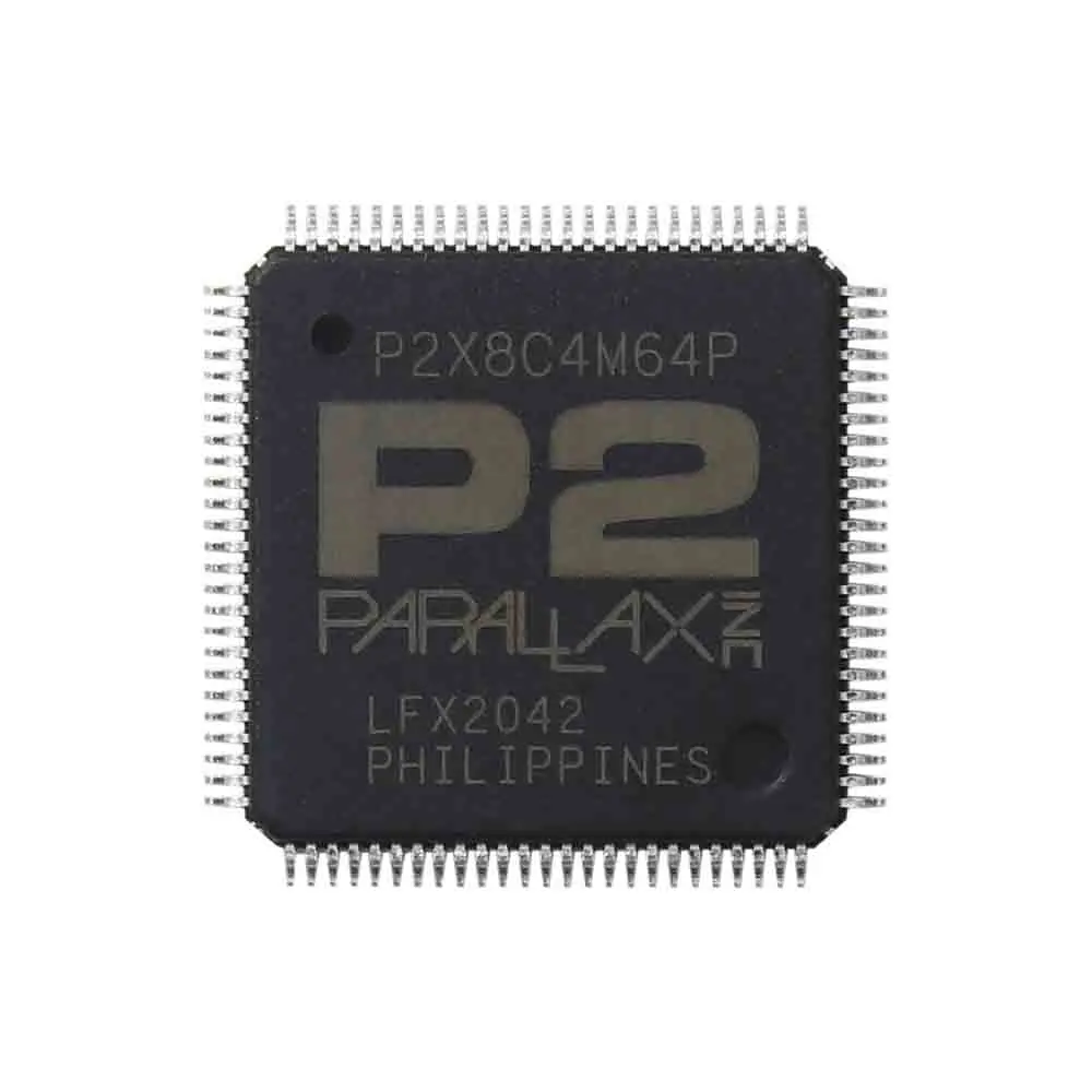
Unrelatedly, if anyone could confer me a transparent PNG of a P2 chip (i.e. without background) or at least a photo on a non-white background, that'd be real swell.
From Parallax's Shop Page: https://parallax.com/shop/
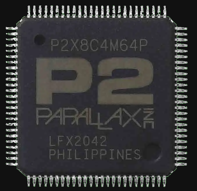
I removed the white background, as much as poible with macOS Preview app:
Just the image from the above website:

dgately
Maybe this will help:
-Phil
There sure is a lot of... green? around the edges
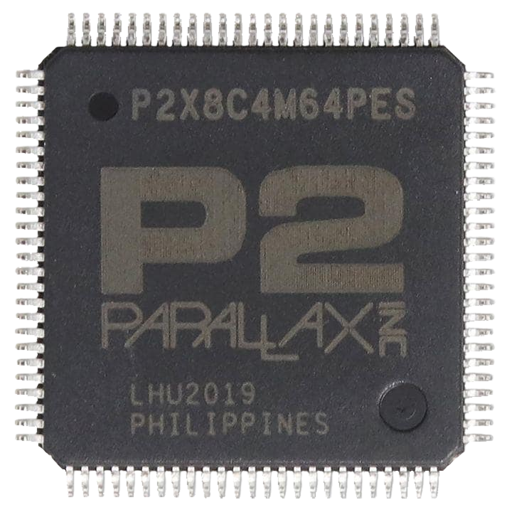
Also, there's a version of the original image that isn't JPEG-d to shit (taken from Mouser I think):
Made this one. Still sucks, but okay enough I guess.
Looks good enough to me.
I wonder if the ES markings won'r raise questions when someone compares this to the "current production" labelling without the ES.
Those who scratch a little deeper, probably all here, will know there is no difference in the chip silicon but the rest, I can't be sure.
Is that why it "still sucks" ?
LMAO didn't even notice the markings being different. It looks so similar to the other image that I thought they were the same.
All my chips are -ES, as they were.
Eitherhow, doesn't really matter, I think.
And no, it sucks because the transparency still isn't perfect. If you look closely you might notice that I applied some gaussian blur to the pin areas to make the edges smoother, lol. And that all after a long manual session with the soft erase tool.
That said, in practice it doesn't look like complete ass, so GoodEnough(tm);
Perfect can still be improved so I'd say stop right there, where you are.
I's much better than good enough.
BTW, @Wuerfel_21 , the HQ image is headed your way soon")
-but yeah, what you have is just fine too.
Might be the first time I've seen the word "DMA" when describing P2. I think it is, but maybe not the usual sort?
Yea, I'm trying to use terms that are perhaps more familiar than the propeller-isms. I would say it's the correct term. It copies between RAM and peripherals. And it also facilitates the all-important external memory transfers.