In your Schematic it shows the coil voltage as 5 VDC, not 24V or 12V. Unless there is a small relay that actuates a larger relay, I can't tell because part of your schematic is cut-off. Post the entire schematic, motors and all. Use a DC voltmeter across the relay coil terminals. Actuate a button for that relay and see if the voltage comes on, should be 5 VDC.
It should be showing an entire page. I know at one point you sent me a pic with it cut off, I thought you were just cropping it. I'll take a picture and upload it.
This is a picture of one of your relay sockets (lower one). Those relays should unplug. The coil voltage and contact rating should be stamped on the side. Looks like the relay has an Led on it, that should light when it's on.
It's hard to see the diode in your picture. But it looks like the coil terminals for ground (Vss) and tied together with a red wire and the purple wire actuates one relay and the gray wire actuates the other relay.
I'm starting to understand how to read the schematic a little now but still a little confused. Why in the schematic does it show my emitter is connected to my relay, but it wasn't done on either board I pulled out. They were only grounded. I did this terrible drawing of what I have going on. My middle emitter is not connected to anything, could that be my problem? The only thing I believe I have tied to VDD (I'm assuming this is my +5 VDC) is my 10K resistor.
Ok, I made some notes on your drawing. Pull the relay and take a picture of the info on the relay, this way I can see the coil voltage. The way your drawing is now it will never work, but you need to look at my notes. The collectors for Fwd (P7 ) and Back (P8) relay, might tie to the 12 VDC supply and not the 5 VDC, if the relays are 12 VDC then those two collectors tie to the 12+ supply . P6 is wired different. You could leave the P6 transistor out for now it only works the light.
Trace those blue wires and see where they connect to. Remember we are working off that original drawing. You need to see if its wired in that manner. I did find some typo's on it, like two P7's when the other should be P6 (light). The collectors for the relays say 5 VDC, that maybe wrong and its 12 VDC, thats why you need to check the specs. on the relay.
Now in your relay picture I see what looks to be a red wire connecting the coil terminals together, do they go to the 12+ power or Vss common ground ? and then you have a purple wire on one and a gray wire on the other relay where do they connect to?
The purple wire goes to the collector on P7, and the grey wire goes to the collector on P8. I've attached another picture because I am not sure how the red wires are tied in besides being bridged.
Ok, Then the red wire is 12+ and the relays are 12 VDC relays. So now we can work one by one. Then the purple wire will go to the middle pin of the tip120 (collector) and the emtter pin will go to Vss (ground common) I don't know wether the purple is Fwd or Back you'll have to figure it out. Vss on the BS2 board needs to tie in with the 12V-. So only work with one relay transistor. If you get that working you can move onto the next. Where is the 12 VDC power supply for the motors come from?
OK I missed that Purple P7 and gray P8, P7 is Fwd and P8 is back. So on your drawing P7 is the middle transistor. You'll need to solder the emitter to Vss. and I guess that middle blue wire on your drawing goes out to the purple.
Other things to check are the TIP120 transistors any good. The diodes on the relays are good etc.. You can pull the BS2 module out of the board and test the relays without it.


Comments
In your Schematic it shows the coil voltage as 5 VDC, not 24V or 12V. Unless there is a small relay that actuates a larger relay, I can't tell because part of your schematic is cut-off. Post the entire schematic, motors and all. Use a DC voltmeter across the relay coil terminals. Actuate a button for that relay and see if the voltage comes on, should be 5 VDC.
I'm sorry, I thought you were able to see the entire thing. I've attached it below.
Ok, Thats the same one, where's the right side half thats cut-off
So, I used my voltmeter across numbers 1 and 8 while activating the relay and both of them read about 12.
It should be showing an entire page. I know at one point you sent me a pic with it cut off, I thought you were just cropping it. I'll take a picture and upload it.
1-8 are not the coil, 2-7 are the coil
Look at this schematic
This one
Check for voltage between terminals 2-7 while actuating the buttons. Should be about 5 VDC
Terminal #2 is the common ground Vss and Terminal #7 connects to the Emitter of the transistor. If you connect 5 VDC to 2-7 the relay should click on.
Terminal #2 is negative and #7 is positive
The transistor with the lamp is just for indication.
This is a picture of one of your relay sockets (lower one). Those relays should unplug. The coil voltage and contact rating should be stamped on the side. Looks like the relay has an Led on it, that should light when it's on.
It's hard to see the diode in your picture. But it looks like the coil terminals for ground (Vss) and tied together with a red wire and the purple wire actuates one relay and the gray wire actuates the other relay.
I see a typo in the drawing P7 for the lamp should be P6
Docx file works, but will be cut off if you rotate the drawing. Need to adjust page size and orientation. At least in office 360.
So, I tested across the coils on each relay and wasn't able to get a reading while pressing either button. At most I think I seen .004.
I'm starting to understand how to read the schematic a little now but still a little confused. Why in the schematic does it show my emitter is connected to my relay, but it wasn't done on either board I pulled out. They were only grounded. I did this terrible drawing of what I have going on. My middle emitter is not connected to anything, could that be my problem? The only thing I believe I have tied to VDD (I'm assuming this is my +5 VDC) is my 10K resistor.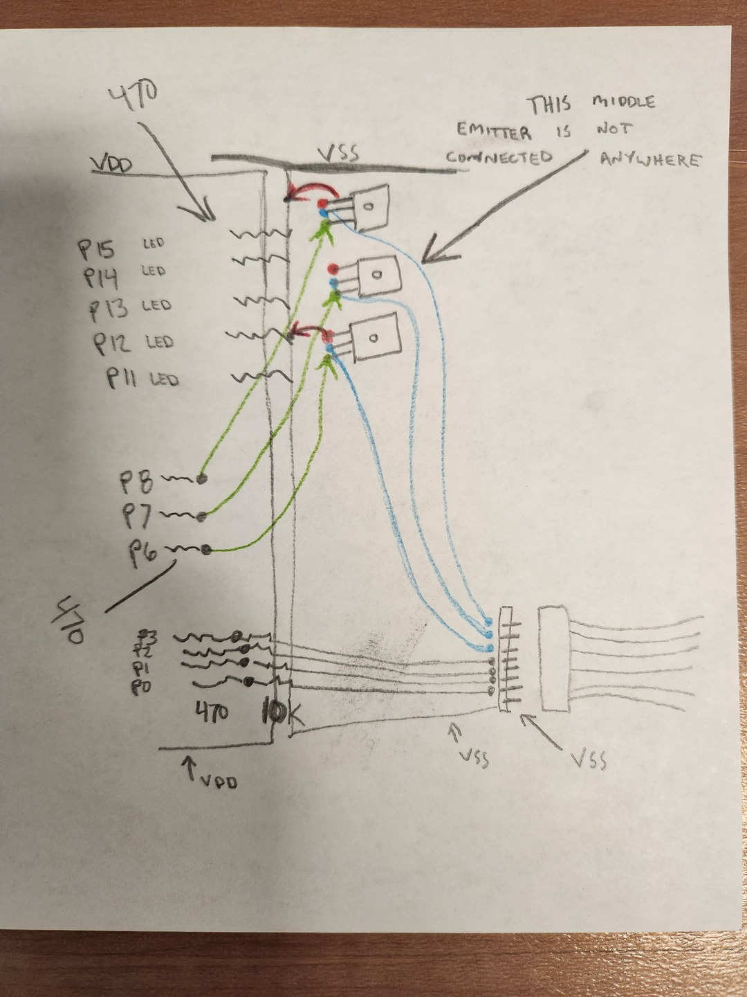
I'm sorry if I am making this harder than what it needs to be, but I do want to say I'm very thankful for all of the help!
Ok, I made some notes on your drawing. Pull the relay and take a picture of the info on the relay, this way I can see the coil voltage. The way your drawing is now it will never work, but you need to look at my notes. The collectors for Fwd (P7 ) and Back (P8) relay, might tie to the 12 VDC supply and not the 5 VDC, if the relays are 12 VDC then those two collectors tie to the 12+ supply . P6 is wired different. You could leave the P6 transistor out for now it only works the light.
Trace those blue wires and see where they connect to. Remember we are working off that original drawing. You need to see if its wired in that manner. I did find some typo's on it, like two P7's when the other should be P6 (light). The collectors for the relays say 5 VDC, that maybe wrong and its 12 VDC, thats why you need to check the specs. on the relay.
Take a look at these notes
Now in your relay picture I see what looks to be a red wire connecting the coil terminals together, do they go to the 12+ power or Vss common ground ? and then you have a purple wire on one and a gray wire on the other relay where do they connect to?
Here is a photo of the relay. OMRON MKS2PI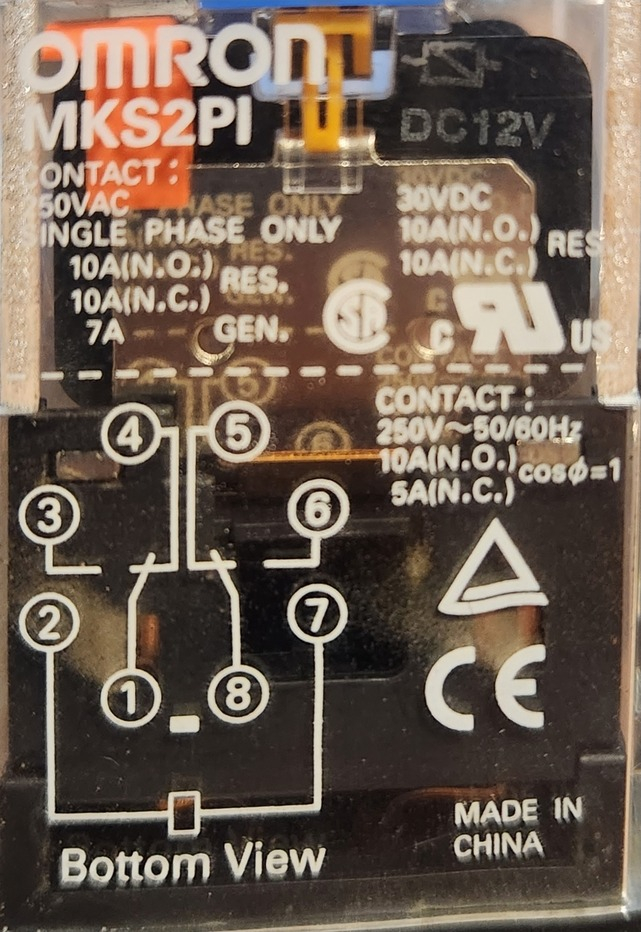
After looking over your notes I believe it is wired like this: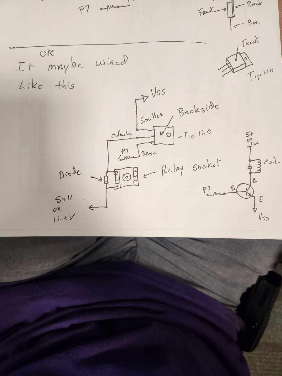
The purple wire goes to the collector on P7, and the grey wire goes to the collector on P8. I've attached another picture because I am not sure how the red wires are tied in besides being bridged.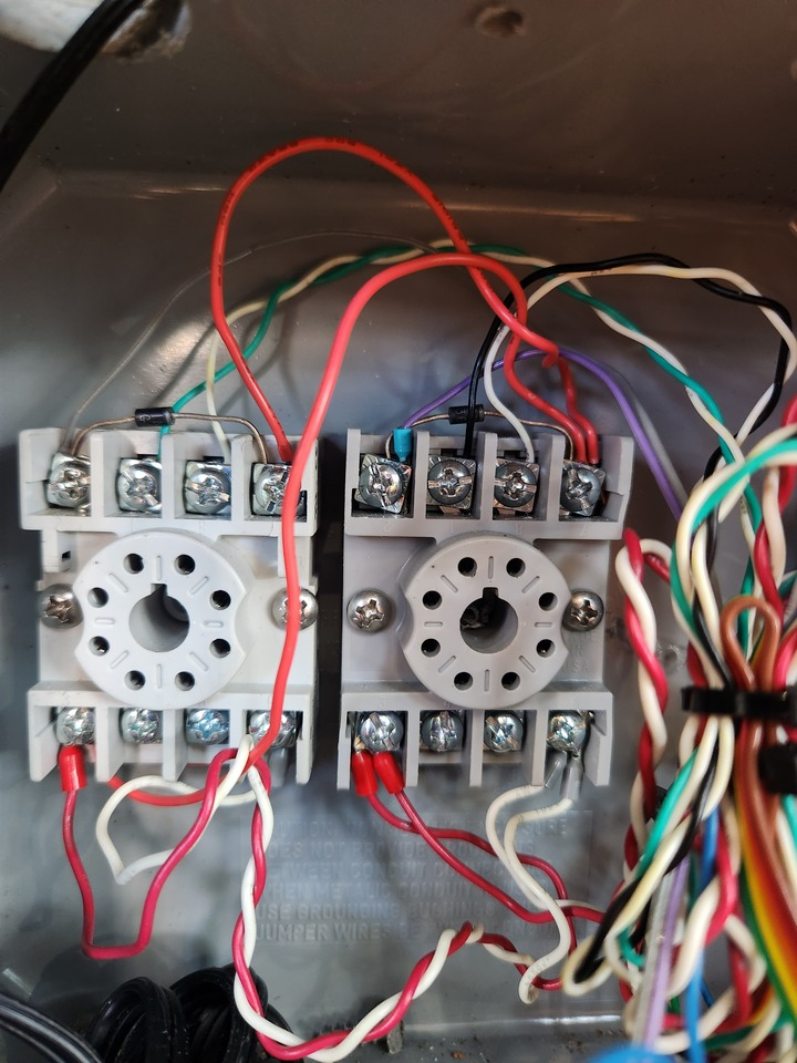
Ok, Then the red wire is 12+ and the relays are 12 VDC relays. So now we can work one by one. Then the purple wire will go to the middle pin of the tip120 (collector) and the emtter pin will go to Vss (ground common) I don't know wether the purple is Fwd or Back you'll have to figure it out. Vss on the BS2 board needs to tie in with the 12V-. So only work with one relay transistor. If you get that working you can move onto the next. Where is the 12 VDC power supply for the motors come from?
OK I missed that Purple P7 and gray P8, P7 is Fwd and P8 is back. So on your drawing P7 is the middle transistor. You'll need to solder the emitter to Vss. and I guess that middle blue wire on your drawing goes out to the purple.
Other things to check are the TIP120 transistors any good. The diodes on the relays are good etc.. You can pull the BS2 module out of the board and test the relays without it.