@rogloh said:
A better Gigatron design would have had a full 8 bit DAC port updating once per scan line, and up to 8 LEDs (or other outputs) latched independently probably on the rising VSYNC edge instead of HSYNC. No need to update diagnostic LED patterns faster than 60Hz. It would only require one more latch, assuming it can be done in the SW timing available. It's certainly possible for a P2 to do if the ROM is adjusted.
Well, Marcel thought the lights would be cool. I guess he remembered the 70s better than I did. They were not really designed to be diagnostic lights, but entertainment. So they can be sequenced with the music, controlled by vCPU programs, etc.
As for strobing based on v-sync, I'm not sure that would work. The keyboard is read then, but yeah, since it is in the ROM and originating on the ROM side, that should be possible. The software-created syncs also replace the role of a PIA. A PIA wouldn't work here (in a first-obvious manner) since there are no interrupts. A PIA is really a collection of shift registers and counters/timers that can throw an interrupt, and then the interrupt handlers collect the data. So the syncs function as interrupts. The reason the X-Out is gated off of the accumulator and not the Out is because for VGA to properly sync, its data lines have to not have current on them. It is called a "blanking interval" for a reason. The CRT guns or equivalent are off as they "retrace." So with VGA, the data lines have to be off at that time. Plus the data signals being off is another sync cue for the monitor. Some VGA monitors allow composite syncs, and the amount of time the data is missing probably helps them to decode which pulse (or absence thereof) is what type. While "official" modes call for a certain polarity, a lot of monitors don't care, so long as it is consistent. That's much like the joke about the cab driver who ran red lights and stopped during green. ("I run red lights because all my brothers do, but I stop during green lights because I don't know when my brothers will be coming through.") So for things like sync polarity differences or weird configurations where the sync wires are tied together, the data lines being blank can fill in the gaps as to what is happening. As for X-Out, yes, it might occasionally disturb the Out lines, but the Out register should correct things fast enough to not affect the monitor.
But yeah, it would be nice if X-Out were just for music. So you can see why I'd want to have a snooping I/O controller and do most stuff in memory. The sound has both input and output "register" locations in memory. While vCPU programs can write to the output port to control the lights (preferably using logical operators rather than "Poke"), they would edit the sound input registers to change the sounds. So an I/O controller would read the respective input memory locations (there should be 8 bytes for channel data) once per scanline, do its own calculations, and send things out to its own port (or pin). So, if that were done, the memory location that X-Out reads from could be used exclusively for lights and you could have up to 8 then. I wouldn't bother with the lights at all, but if you have something else reading the music from the 16-bit locations, the "register" that holds things for the X-out would not be needed for sound.
I now have Babelfish for the Gigatron ported to the P2 by starting out with Babelfish.ino C/C++ application and converting it to SPIN2 and running it on a third COG. I've also replaced the PS2.ino stuff with USB keyboard support.
Today I tested out many of its features which seem to be working. The following is still left to test/add:
EEPROM support - right now it saves to HUB RAM but I could probably get it to write saved files into P2 flash
Transfer object from USB. When I had a quick look the python sendfile.py code that runs on the host it seemed to be looking for USB serial ports coded with Arduino PIDs/VIDs. May need some mods to work with general serial ports if that is not supported. Have to investigate if that is the case, have not tried it yet.
I did also convert some of the PS/2 code to SPIN2 but have only included the USB keyboard for now. It may be possible to use PS/2 instead eventually or as an option but I first need to make an adapter to let me connect a real PS/2 keyboard to the P2.
I probably will also include the USB controller that I had working outside of Babelfish and the real Famicon controller too as options. Right now the game controller stuff is disabled to not interfere with Babelfish which is using these same game controller pins feeding into Gigatron but this could be merged back with a Smartpin doing a logical and of two pins or letting Babelfish do the polling of the game controller (like it was also designed to do).
A short serial output log from the P2 serial port is shown below showing it running and a picture of the key mapping feature it can trigger. Man that 3x5 font is small, yet still somewhat readable.
RLs-MacBook-Pro:gigatron roger$ loadp2 -t giga.binary
( Entering terminal mode.  Press Ctrl-] or Ctrl-Z to exit. )
:BabelFish platform=Propeller2
:Pins:
: Gigatron data=8 latch=7 pulse=6
: Keyboard clock=40 data=41
: Controller data=-1
:EEPROM:
: size=32768 mapping=US
:PROGMEM slots:
: P0) BASIC
: P1) WozMon
: P2) Terminal
: P3) Blinky
: P4) Lines demo [at67]
: P5) Game of Life demo [at67]
: P6) Starfield demo [at67]
: P7) Bricks game [xbx]
: P8) Tetronis game [at67]
: P9) -SAVED-
:Echo off
:Type 'H' for help
:Gigatron OK
Cmd?
:Commands are
: V        Show configuration
: H        Show this help
: R        Reset Gigatron
: L        Start Loader
: M        Show key mapping or menu in Loader screen
: P[<n>]   Transfer object file from PROGMEM slot <n>
: P9       Type saved EEPROM data back into Gigatron
:          [Hint: Use '.SAVE' for saving, not 'T'-mode!]
: U        Transfer object file from USB
: .<text>  Send text line as ASCII keystrokes
: B<n>...  Send list of bytes
: C        Toggle echo mode (default off)
: T        Enter terminal mode
: W/A/S/D  Up/left/down/right arrow
: Z/X      A/B button
: Q/E      Select/start button
:Gigatron OK
Cmd?
:Starting Loader from menu
:Gigatron OK
Cmd?
:Sending from PROGMEM
:Loading 16 bytes at $00E0
:Loading 88 bytes at $0200
:Loading 169 bytes at $0300
:Loading 182 bytes at $0400
:Loading 144 bytes at $0500
:Loading 16 bytes at $0590
:Loading 48 bytes at $05A0
:Loading 50 bytes at $08A1
:Loading 74 bytes at $09A1
:Executing from $0200
:Gigatron OK
Cmd?
As a side comment on the Blinkenlights, that reminds me of a program I wrote on a 286 or 386 in Quickbasic. I toggled the keyboard statuses to blink the keyboard lights and restored what was there when the program exited. But then I discovered my code would crash an XT. Apparently, the keyboard stuff is in different places in memory. So it was possible I was changing the values in the PIT chip, and the DRAM refresh uses a channel. If you set the DRAM refresh to an abnormally low value, you trash the memory. So I added a CPU detection routine, and if an 8088 or V20 were found, it would skip the keyboard flashing routine. Speaking of the PIT, I think that was a 3-channel chip. There was the system counter (not to be confused with the system clock or the counter register CX), the DRAM refresh, and a spare that could be gated to the speaker (unless you wanted to bit-bang and toggle the speaker manually). That's one thing I didn't like about the PC platform. It only had one single-bit sound channel. At least the Tandy 1000 added the TI sound chip, and newer ones of the series also added a DAC and sample port. So you could, in theory, have 6 different sounds. (Three tones from the PSG, a noise from the PSG, a tone through the PC speaker, and a sample out the DAC.)
I was able to get the python3 sendFile.py loader program to download .gt1 files to the Gigatron Babelfish code running within the P2 so it can now play those fun Gigatron games like PucMon and Invaders...which are rather decent ports for such a simple machine that this is. It's 4bit audio seems quite a bit cleaner running those than playing the startup sound.
I added back the Famicon game controller support using a Smartpin doing a logical AND with real device pin input and its own local keyboard output generated by the Babelfish software inside. This is nice because it is transparent and no code is needed. Just don't try to press controller and keys at the same time...
I will update another ZIP soon with this latest stuff but first I just want to tidy up some USB keyboard issues I have right now.
I also tested load and save from Basic to HUB RAM as an emulated EEPROM (not FLASH yet), and that feature works too.
So most things are actually working. No PS/2 (yet) or a USB based game controller. I do intend to put back the latter feature in the build as not everyone would have the (S)NES based controller, USB ones are more common these days I suspect.
RLs-MacBook-Pro:gigatron roger$ python3 sendFile.py ~/Downloads/PucMon_ROMv5a.gt1
Connecting to /dev/cu.usbserial-AD01TB6Q (FT232R USB UART - FT232R USB UART)
Resetting Gigatron
Starting Loader
Sending program '/Users/roger/Downloads/PucMon_ROMv5a.gt1'
.....................................................................................................................................................................................................................................................................................................................................................................................................................................................................................................................................................................................................................................................................................................................................................................................................................................................................................................................................................................................................................................................................................................................................................................................................................................................................................................................................................................................................................
Finished
RLs-MacBook-Pro:gigatron roger$ python3 sendFile.py ~/Downloads/gtsokoban
gtsokoban.gt1        gtsokoban64k_v1.gt1
RLs-MacBook-Pro:gigatron roger$ python3 sendFile.py ~/Downloads/gtsokoban.gt1
Connecting to /dev/cu.usbserial-AD01TB6Q (FT232R USB UART - FT232R USB UART)
Resetting Gigatron
Starting Loader
Sending program '/Users/roger/Downloads/gtsokoban.gt1'
...............................................................................................................................................................................................................................................................
Finished
RLs-MacBook-Pro:gigatron roger$ python3 sendFile.py ~/Downloads/Invader.gt1
Connecting to /dev/cu.usbserial-AD01TB6Q (FT232R USB UART - FT232R USB UART)
Resetting Gigatron
Starting Loader
Sending program '/Users/roger/Downloads/Invader.gt1'
.......................................................................................................................................................................................................................................................................................................................................................................................................................................................................................................................................................................................................................................................................................................................................................................................................................................................................................................................................
Finished
@rogloh said:
Partials is certainly possible when the code is being executed without branching. In that case the FIFO (already filled from some prior RDFAST) will slowly deplete byte by byte, one byte being read per XBYTE and another "D" argument byte read by each instruction handler. In theory eventually this depletion will retrigger a FIFO refill which may upset things. This is probably the only unknown left IMO.
After further testing, I have seen partial FIFO refilling in action. Code to detect it involves precise timing and I'll explain more later.
Below is the code I use for FIFO testing that involves timing. It is hopeless trying to count cycles if you do not know the exact hub RAM slice at the start. Slice = hub address[4:2] = 0-7.
        rdbyte  $1ff,#0     'sync to egg beater slice 0
        getct   t0          'this does not delay rdfast
        rdfast  #0,#0       'load FIFO starting at slice 0
        waitx   #16-2       'FIFO full before end of wait
'       ...                  other instructions
        getct   t

'rdfast ends 16 cycles after rdbyte ends,
'however FIFO still loading after rdfast and
'need to wait >= 10 cycles before hub read/write
'other instructions take t-t0-16-waitx cycles
'rdfast post-read of 5 cycles use slices 1-5,
'therefore first slice after rdfast is 6
Using the code above it is possible to test various things:
Example 1
One can confirm the FIFO depth by filling the first 32 longs of hub RAM with zeroes, then do RDFAST and WAITX as shown above, then fill the first 32 longs with 1,2,3,...,32, then do RFLONGs until a non-zero value is read that is the FIFO depth + 1.
Example 2
Same as example 1, but insert one RFLONG immediately after the WAITX. What should the non-zero value be?
Example 3
Same as example 2, but insert two or three or four or five RFLONGs.
Example 4
Same as example 2, but insert six RFLONGs.
Cycle timing is not important in any of these cases.
To tie this with my other thread, starting a vCPU-only Gigatron project could tie in. I mean, it wouldn't hurt to throw in the 6502 core. And then emulating old Apple programs would be easier. The Gigatron includes a 6502 in ROM (and even an instruction that was broken on the original CPU but works in the emulator) and a few programs that use it. That can be left out, but the 6502 core provides a more efficient way to use those. And even if I were to gate that to the syncs, at the speed needed to do the Gigatron, even that would give you maybe 3 Mhz performance, which is still faster than 1.79 Mhz or whatever they ran at.
If any cogs are left, one could add the option to run pure P2 code and be able to interface with the existing peripherals designed for the other cores. And something that would be nice would be to port AT67's compiler BASIC to emit native P2 code. In other words, make it to where it still obeys the Gigatron's memory map (for the first 32K). Of course, one is free to start with a clean slate for that mode. However, it would be nice to take the source code of the games and make them able to compile into P2 code. So keeping things in the places where the Gigatron programmers know them to be would make the programs work right away without significant changes.
One thing I wish Marcel had done was to include an indirection table vector. It would be nice if you could move that sucker around. So if a higher-res video mode needs a larger one or one in a different place, that would be easy to do without doing weird banking stuff to account for extra rows, etc.
Now that Babelfish is integrated I could free up 9 instructions that were used before to merge keyboard data with game controller data. This allowed me to add video scan line replication in the IO COG code, so now Gigatron can always operate at the highest CPU speed giving 3/4 of the scan lines to the CPU vs outputting active video, and the P2 will replicate the missing scan lines for it on the VGA port. I just used the LUTRAM to store the source video data every 4th scan line and read from it for the other 3 scan lines. I had to reduce the active loop down to 25 instructions instead of 26 because RDLUT takes 3 clocks instead of 2 like the rest of the instructions in the loop but I can do this and the waitse1 and xcont will sort that out and keep the loop period running at 52 clocks per pixel. In fact there is scope to remove 2 more instructions in the loop, or 3 if I want to use the upper half of LUT for video palette data instead of COGRAM (but this is risky if you ever miss a horizontal sync pulse, so for now I use COGRAM for the palette).
The only issue with this is that it is hard to know what the current setting is when you cycle through the steps with the select button because it is not visible on the screen any more and you can only go by the observed CPU speed up or slow down. If there was a way to show the current setting via feedback on screen as you cycle through that would be nicer.
reploop                     rep         #25, #0                 ' 52 clock cycle loop max
                            waitse1                             ' wait for repository
                            rdpin       outputdata, #OUT_REPO   ' get video data
                            cmp         linecounter, #480 wc    ' c=1 if in active portion
                            test        linecounter, #3 wz      ' z=1 if the 0th, 4th, 8th... line we source from
            if_nz_and_c     rdlut       outputdata, ptra++      ' load from LUT RAM
            if_z_or_nc      wrlut       outputdata, ptra++      ' write to LUT
                            testpn      #EGA_BASE_PIN+HSYNC wc  ' c=1 if previously low
                            testbn      outputdata, #VSYNC wz   ' get vsync pin state
                            alts        outputdata, #colourmap
                            xcont       vgaout, 0-0             ' send pixel to VGA port
                            drvnz       #VGA_VSYNC_PIN          ' copy vsync state
                            testb       outputdata, #HSYNC andc ' test if current hsync is high

            if_nc           jmp         #reploop                ' we are done if not the rising hsync edge

                            testb       lastvsync, #VSYNC andz  ' z=1 if falling high->low edge
                            mov         lastvsync, outputdata
                            movbyts     outputdata, #%%3322

                            mov         ptra, #0                ' reset pointer
            if_z            mov         linecounter, #485       ' resync counter (value experimentally found)
                            incmod      linecounter, const520   ' 521 lines/frame

                            ' light LEDs
                            setnib      LED_PORT, outputdata, #LED_NIB ' drive LEDs

                            ' output audio DAC data
                            and         outputdata, audiomask       ' remove LED data
                            wypin       outputdata, #AUDIO_DAC_PIN  ' update DAC value

                            ' write last input data to repo (1 shift clock lag)
                            wxpin       inputdata, #IN_REPO

                            testp       #CTRL_DATA_PIN andc     ' read from input controller
                            rcl         inputdata, #1           ' shift into input data, repeat loop ends here
The only issue with this is that it is hard to know what the current setting is when you cycle through the steps with the select button because it is not visible on the screen any more and you can only go by the observed CPU speed up or slow down. If there was a way to show the current setting via feedback on screen as you cycle through that would be nicer.
I think what I can do is add an IO pin that is raised via an internal pullup each time the Select button is pressed/held as detected by the controller code. Then the IO COG will OR its C flag with this pin state and that will disable the scan line replication. You could have an external pushbutton on this pin too to show the current setting each time it is pressed. If the user wants to disable line replication completely they could strap it high (via a pullup) too. This will only take one more instruction in the IO COG.
Another idea could be to have an OSD feature, even if for other/future designs. Maybe design a hardware sprites feature and use it for the mode selection thing and only leave it up for maybe 180 frames or so.
@PurpleGirl said:
Another idea could be to have an OSD feature, even if for other/future designs. Maybe design a hardware sprites feature and use it for the mode selection thing and only leave it up for maybe 180 frames or so.
Yeah lots of things are possible if you run the video in it's own COG. Particularly if it is decoupled from the IO COG and has more cycles per pixel. Ideally it could read text from a frame buffer in RAM but the Gigatron doesn't work that way. Only specially written programs would be able to make use of that.
BTW I just fixed the USB keyboard problem I had. The ported code was using millis() from Arduino and it used 16 bit values for its keypress hold timeouts but getms() on P2 returns a 32 bit value so it wrapped into the high word after a minute, messing things up. Fixed by making it all 32 bits so wrap can be handled.
I still want to add the second USB port back in to allow USB game controllers, retest, and then release this. I don't think I'll need to do PS2 keyboards right now.
Yeah, I get you. Yeah, the way text is rendered is for the user to call a syscall (maybe) or do the lookup themselves and put that in the frame buffer. There is no mode where you can put 300 bytes in a buffer and it gets converted to bitmap format on the fly. I don't know what the text res would be for sure, but dividing 8 into both dimensions gives 20x15.
On the cogs and video, I got to thinking of something. The Atari TIA required that programmers know the state of the screen. So one had to chase the beam in the code. One useful feature in helping with that was the variable pixel rate. The Gigatron could do the variable pixel rate thing, and that's how it skips lines. The Out register can hold the same value for as long as you need. Of course, with everything being a bitmap and the way the vCPU works, that feature cannot really be utilized. There could be some compression, but then you'd need calculation time. Now, it does actually have a simple compressor and decompressor. Due to it using 6-bit video, 4 pixels can be stored in 3 bytes. But that isn't for displaying out of, but for unpacking from ROM or whatever.
Anyway, some old platforms used a display list format. The Atari 800 used Antic and GTIA together. They need things needed to be more flexible for coders, have more graphics capabilities, and not use up a lot of RAM. So Antic offloaded a lot of the work from the coder and sent it to the GTIA, and everything was done in real-time. One chip rendered it a line at a time and the other chip displayed it. So for a different type of project, that might be feasible. Have one cog reading the hub RAM and assembling several lines at a time and the other cog reading the LUT and displaying from there. Maybe the first cog could cache the display list buffer plus any sprite/PMG buffers and produce output for the 2nd cog a line at a time. There could be maybe a handshake mechanism and the rendering could start a line or 2 in advance. So the one cog works as fast as it can and guarantees at least 1 rendered line per H-sync but likely gets ahead by several. And if you have line multiplication, it is free to do more work, since the work is done once per actual line cluster. Thus by buffering several lines ahead, it is free to render the occasionally more complex lines and not let the line buffers run dry.
Even some FPGA designs use this. They have only so much BRAM, and only so much bandwidth for external RAM, though you tend to have enough lines to do it in parallel. Typically, in ASRAM, about 10 ns is about as fast as you can go (though 7-8 ns can be found on rare occasions). And SSRAM is quite complex as it is synchronous and is usually DDR or QDR (a misnomer since you rarely get 4x the speed unless you do 2 interleaved sets of reads and writes during the same clock). That's essentially CPU cache RAM and can be as fast as 300 ps (theoretical maximum of 3.3 GHz). I wouldn't know how to use that. But anyway, someone had a tesselator project, and to deal with the memory problem, they rendered it on the fly. So stateless video can likely be something to do on the P2.
On screen Gigatron's menu seems to use a 5x7 font in a 6x8 character cell size. This gives it 26 characters (and two unused pixels) on the 160 pixel scanlines. It is 15 rows as you stated in the 120 lines.
The Babelfish application renders text with an even smaller 3x5 font (!) in a 4x6 character cell size yielding a surprisingly legible 40x20 screen. The font only takes up 192 bytes!
@rogloh said:
On screen Gigatron's menu seems to use a 5x7 font in a 6x8 character cell size. This gives it 26 characters (and two unused pixels) on the 160 pixel scanlines. It is 15 rows as you stated in the 120 lines.
The Babelfish application renders text with an even smaller 3x5 font (!) in a 4x6 character cell size yielding a surprisingly legible 40x20 screen. The font only takes up 192 bytes!
So more like 390 characters or 800 for the app you mentioned. And if one wanted to do the text as MS-DOS did, you could double it that to include an attribute table. So 16 foreground and 16 background colors.
Yeah you do a coloured text screen with 1600 bytes in HUB RAM with the small font.
But you could also do better than this because my prior video driver work already supports PC style 80xn text resolutions where n=480/font height in scan lines (assuming 640x480 VGA output).
Found one problem.
With this MS Basic port from 6502 on the Gigatron, it can't seem to save without messing up the video output. It could to be something internal to the Gigatron or a bug in the BASIC causing a crash and loss of video when you try to save. It's not a total lockup because a RESET command issued from Babelfish recovers it. Also the SAVE to EEPROM function works from the other BASIC supplied (TinyBASIC) so it's not something in that code.
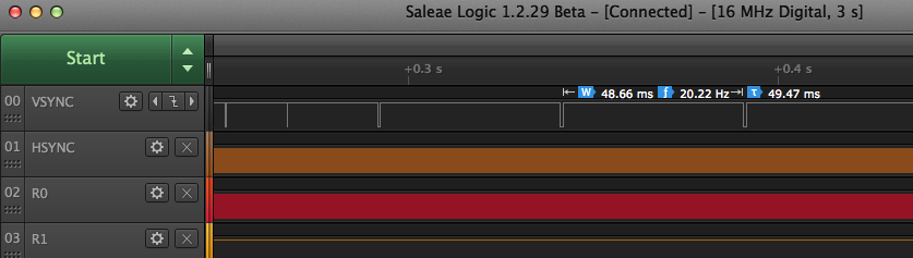
I did some LA captures and found that the HSYNC and VSYNC timing goes awry right after issuing the SAVE command in MS BASIC. The zooming level increases between each capture below. You can see the orange HSYNC trace starts to become a messy pattern when it happens. The Red (R0) trace is actually my 3.125MHz CPU clock per instruction (6.25MHz toggle rate) and while I couldn't display the entire signal between the HSYNCs below, when I scanned through it it doesn't seem to noticeably slip somewhere. It's like the Gigatron just loses count of its video timing once you start saving and it doesn't want to recover. Maybe a bug in the ROM, or something in my emulator?
While stuck in the bad state the VSYNC rate seems to be about 20Hz but the HSYNCs are being issued all over the place in a semi-random looking way.
@rogloh said:
Found one problem.
With this MS Basic port from 6502 on the Gigatron, it can't seem to save without messing up the video output. It could to be something internal to the Gigatron or a bug in the BASIC causing a crash and loss of video when you try to save. It's not a total lockup because a RESET command issued from Babelfish recovers it. Also the SAVE to EEPROM function works from the other BASIC supplied (TinyBASIC) so it's not something in that code.
I did some LA captures and found that the HSYNC and VSYNC timing goes awry right after issuing the SAVE command in MS BASIC. The zooming level increases between each capture below. You can see the orange HSYNC trace starts to become a messy pattern when it happens. The Red (R0) trace is actually my 3.125MHz CPU clock per instruction (6.25MHz toggle rate) and while I couldn't display the entire signal between the HSYNCs below, when I scanned through it it doesn't seem to noticeably slip somewhere. It's like the Gigatron just loses count of its video timing once you start saving and it doesn't want to recover. Maybe a bug in the ROM, or something in my emulator?
That is by design. The game port is an input-only port. So to send output to it, you manipulate the V-sync to send very slow output to the controller, and yes, you get screen artifacts.
@PurpleGirl said:
I wonder, could this non-standard V-sync behavior somehow be throwing off the emulation timings?
It shouldn't be possible for it to do that. The code that outputs video to VGA and EGA pins doesn't exactly care what it sends. Yes it will mess up the video if corrupted but that should not affect emulator timing which once started just captures the OUTPUT port data every 52 P2 clocks. I sort of think there must be a bug in a branch handler somewhere, called by the SAVE handler in 6502 MS BASIC crashing it and messing up what gets captured after this or leading to an overflow of the cycle budget if it was somehow triggering something FIFO related. The problem is I am no 6502 expert and to debug it there's the MS BASIC application running on a 6502 emulator, running on virtualized vCPU, running on Gigatron, running on my P2 emulator. It's turtles all the way down. I thought I might possibly be able to log the native Gigatron instructions being executed but I don't know really what they should be to know if it's doing the right thing or not. I'm a little worried about some page wrap jump thing at the last byte of the page in the SAVE code. AFAIK I'm handling all branches correctly but not 100% convinced. I do know my emulator can't handle instruction wrapping around at the 128kB ROM boundary, but hopefully nothing intentionally does that.
I've got the USB game controller back in, so now there are 4 ways to control it again:
1) a USB keyboard
2) the USB gamepad(s) supported by NeoYume (including two of mine I added)
3) Famicon/(S)NES protocol game controllers
4) console from PC/laptop over USB serial to P2
I think I will zip and post this emulator this afternoon for anyone to try out who has a P2 board (P2-EVAL or P2-Edge should be fine) and the breakouts (A/V and USB). I'll probably include the v5a ROM and its LICENSE (BSD 2-clause) this time too. Since they've been openly posted on the Gigatron forums by their original author I think it would probably be okay to include PucMon and Invaders .gt1 files, but you can source them from here: https://forum.gigatron.io/viewtopic.php?p=1523#p1523 https://forum.gigatron.io/viewtopic.php?p=1600#p1600
Here's the 0.9 release. You need to build and run the gigatron.spin2 file with flexspin. PropTool/PNut doesn't support including text files with #include so it doesn't work on those. It potentially could otherwise.
@rogloh said:
Here's the 0.9 release. You need to build and run the gigatron.spin2 file with flexspin. PropTool/PNut doesn't support including text files with #include so it doesn't work on those. It potentially could otherwise.
There's another idea. On the Pluggy writing bug, have you tried one of the DevROM versions? AT67's DevROM fixed some bugs in 5A and added features.
I haven't tried that yet, but could. Right now I am just trying to time the clock output to make sure it is always 52 clocks between edges, but am having troubles getting the Smartpin to report to me in this P_HIGH_TICKS measuring mode - right now it's always reading zero which isn't helpful. Still investigating...
Ok, so I got the Smartpin reading the clock cycles. I do see something happen when I save from MS BASIC. I am meant to be counting clock cycles, but for some reason it reports 53 instead of 52 clocks - might be something with the way Smartpin reports time between edges (including both edges?) or we really are clocking at 53 clocks instead of 52. In any case, that's not the issue, the issue happens when I do a SAVE command and this is what occurs. I am printing out two decimal values each time I hit enter on the keyboard. First one is the latest interval between clock edges, and second is highest value observed so far (no samples should be lost). For some reason it takes an extra clock cycle when I type SAVE and this messes things up.
53 53:Gigatron OK
Cmd?
53 53:Gigatron OK
Cmd?
53 53:Gigatron OK
Cmd?
53 53!Gigatron offline   <<---- hangs after here
Cmd?
53 54!Gigatron offline
Cmd?
53 54!Gigatron offline
Cmd?
53 54!Gigatron offline
Cmd?
53 54!Gigatron offline
Cmd?
Here's the timing COG pin monitoring logic - smart pin 12 is reading from pin 9 (the instruction clock output meant to be toggling at 3.125MHz). It also updates some LEDs and writes its (current, max) values to HUB which is read by prior printing COG.
DAT

    orgh

monitor
    org
            fltl #12
            wrpin ##P_MINUS3_A | P_HIGH_TICKS, #12 ' reading from clock output on pin 9 as "A" input pin
            drvl #12
            mov pa, ##_clkfreq ' wait a second to start
            dirh #32 + 3<<6
            wrlong #0,#0
            wrlong #0,#4
            waitx pa
poll1
            testp #12 wc
    if_nc   jmp #poll1 ' skip the first reading in case it's trash
            rdpin val, #12

poll2
            testp #12 wc
    if_nc   jmp #poll2
            rdpin val, #12
            cmp val, #52 wz ' should be 52 clocks always
    if_z    jmp #poll2

            setnib outb, onleds, #0 ' increment a counting pattern on the LED board
            add onleds, #1
            wrlong val, #0 ' dump value to HUB - read from another COG
            cmp max, val wc
   if_c     mov max, val
            wrlong max, #4 ' dump value to HUB - read from another COG
            jmp #poll2

val         long 0
max         long 0
onleds      long 1
However if I increase the instruction cycle budget to 54 or 56 (P2 @350MHz) it still doesn't fix the problem, and doesn't even report over 56 clocks in the latter case, yet the video still messes up. It's weird.
Cmd?
56 56:Gigatron OK
Cmd?
56 56:Gigatron OK
Cmd?
56 56!Gigatron offline  <---- hangs after here
Cmd?
56 56!Gigatron offline
Cmd?
56 56!Gigatron offline
Cmd?
56 56!Gigatron offline
As well as the other ROM, I might be able to try to dump the current timer's LSBs on a 6 pin group and monitor with the logic analyzer. I could possibly also dump the instruction to a group of 8 pins too so we get a log of the sequence but it's not probably fast enough to sample in real time accurately and difficult to test exactly without the video working and my monitor won't accept very low hsync rate signals.
Found two things that help a bit with the timing variation I was seeing above.
Moving to 54 P2 clocks between Gigatron instructions (337.5MHz P2) and using XZERO instead of XCONT which zeroes the streamer phase per pixel stabilizes things. The use of XCONT will otherwise wrap around the 32 bit NCO counter periodically and introduce a clock timing shift due to quantization errors.
I was hoping this might improve the audio quality a little bit too but doesn't seem to.
Unfortunately despite this change I still get the MS BASIC SAVE errors, even though that operation doesn't seem to be changing the instruction timing any more. So something else is still causing it.
The current/Max counters are stable when I use 54 clocks per emulated instruction. The third value below is a counter ticking each time there is a reading not equal to 54 and it gets initialized to 1, basically it has never seen anything other than a 54. The last number is something else that can be ignored here.
54 54 1 -51909628:Gigatron OK
Cmd?
54 54 1 -51909628:Gigatron OK
Cmd?
54 54 1 -51909628!Gigatron offline  <-- SAVE fails here.
Cmd?
54 54 1 -51909628!Gigatron offline
Cmd?
Yeah, I found the message where someone from Gigatron.io came here and told us where to get it, and yeah, one would have to build it as they don't have a compiled ROM sitting in the repository:
Ok, so I just built and tried out the DEV ROM instead of V5A ROM, no luck with improving the SAVE problem in MS BASIC.
I think this is either:
a real bug in Gigatron MS BASIC SAVE code - surely others would have reported it by now.
a bug in my emulator somewhere, possibly branch related yet only seen with MSBASIC SAVE instruction sequence?
or something to do with the FIFO potentially returning bad read data somehow due to my aggressive timing in the instruction handlers
EDIT: It could also be a real timing problem in Gigatron where the executed code is not 100% deterministic fitting in the scan line budget. For a regular bit banged output by Gigatron some occasional video artifacts like this are probably okay, but syncing things with XCONT on P2 doesn't like it.
With the monitoring code running I have observed that there are no instructions taking longer than 55 clocks. Strange I thought it was reporting 54 last night but it's 55 today.
I'm going to have a brief look at what's needed for enabing a PS/2 keyboard (if it's simple to realize I might include it as well as I've already done most of the coding work for it), and then tidy up the IO pin mapping, bundle it up as a 1.0 and probably leave it alone.
Now you see why one might want to emulate vCPU instead since then with the "supervisor" cog idea and separate storage cog, one can come up with another way (and much faster) to load and save things. Just use the syscalls as hooks and do it however appropriate for a P2.


Comments
Well, Marcel thought the lights would be cool. I guess he remembered the 70s better than I did. They were not really designed to be diagnostic lights, but entertainment. So they can be sequenced with the music, controlled by vCPU programs, etc.
As for strobing based on v-sync, I'm not sure that would work. The keyboard is read then, but yeah, since it is in the ROM and originating on the ROM side, that should be possible. The software-created syncs also replace the role of a PIA. A PIA wouldn't work here (in a first-obvious manner) since there are no interrupts. A PIA is really a collection of shift registers and counters/timers that can throw an interrupt, and then the interrupt handlers collect the data. So the syncs function as interrupts. The reason the X-Out is gated off of the accumulator and not the Out is because for VGA to properly sync, its data lines have to not have current on them. It is called a "blanking interval" for a reason. The CRT guns or equivalent are off as they "retrace." So with VGA, the data lines have to be off at that time. Plus the data signals being off is another sync cue for the monitor. Some VGA monitors allow composite syncs, and the amount of time the data is missing probably helps them to decode which pulse (or absence thereof) is what type. While "official" modes call for a certain polarity, a lot of monitors don't care, so long as it is consistent. That's much like the joke about the cab driver who ran red lights and stopped during green. ("I run red lights because all my brothers do, but I stop during green lights because I don't know when my brothers will be coming through.") So for things like sync polarity differences or weird configurations where the sync wires are tied together, the data lines being blank can fill in the gaps as to what is happening. As for X-Out, yes, it might occasionally disturb the Out lines, but the Out register should correct things fast enough to not affect the monitor.
But yeah, it would be nice if X-Out were just for music. So you can see why I'd want to have a snooping I/O controller and do most stuff in memory. The sound has both input and output "register" locations in memory. While vCPU programs can write to the output port to control the lights (preferably using logical operators rather than "Poke"), they would edit the sound input registers to change the sounds. So an I/O controller would read the respective input memory locations (there should be 8 bytes for channel data) once per scanline, do its own calculations, and send things out to its own port (or pin). So, if that were done, the memory location that X-Out reads from could be used exclusively for lights and you could have up to 8 then. I wouldn't bother with the lights at all, but if you have something else reading the music from the 16-bit locations, the "register" that holds things for the X-out would not be needed for sound.
I now have Babelfish for the Gigatron ported to the P2 by starting out with Babelfish.ino C/C++ application and converting it to SPIN2 and running it on a third COG. I've also replaced the PS2.ino stuff with USB keyboard support.
Today I tested out many of its features which seem to be working. The following is still left to test/add:
sendfile.pycode that runs on the host it seemed to be looking for USB serial ports coded with Arduino PIDs/VIDs. May need some mods to work with general serial ports if that is not supported. Have to investigate if that is the case, have not tried it yet.A short serial output log from the P2 serial port is shown below showing it running and a picture of the key mapping feature it can trigger. Man that 3x5 font is small, yet still somewhat readable.
As a side comment on the Blinkenlights, that reminds me of a program I wrote on a 286 or 386 in Quickbasic. I toggled the keyboard statuses to blink the keyboard lights and restored what was there when the program exited. But then I discovered my code would crash an XT. Apparently, the keyboard stuff is in different places in memory. So it was possible I was changing the values in the PIT chip, and the DRAM refresh uses a channel. If you set the DRAM refresh to an abnormally low value, you trash the memory. So I added a CPU detection routine, and if an 8088 or V20 were found, it would skip the keyboard flashing routine. Speaking of the PIT, I think that was a 3-channel chip. There was the system counter (not to be confused with the system clock or the counter register CX), the DRAM refresh, and a spare that could be gated to the speaker (unless you wanted to bit-bang and toggle the speaker manually). That's one thing I didn't like about the PC platform. It only had one single-bit sound channel. At least the Tandy 1000 added the TI sound chip, and newer ones of the series also added a DAC and sample port. So you could, in theory, have 6 different sounds. (Three tones from the PSG, a noise from the PSG, a tone through the PC speaker, and a sample out the DAC.)
I was able to get the python3
sendFile.pyloader program to download .gt1 files to the Gigatron Babelfish code running within the P2 so it can now play those fun Gigatron games like PucMon and Invaders...which are rather decent ports for such a simple machine that this is. It's 4bit audio seems quite a bit cleaner running those than playing the startup sound.I added back the Famicon game controller support using a Smartpin doing a logical AND with real device pin input and its own local keyboard output generated by the Babelfish software inside. This is nice because it is transparent and no code is needed. Just don't try to press controller and keys at the same time...
I will update another ZIP soon with this latest stuff but first I just want to tidy up some USB keyboard issues I have right now.
I also tested load and save from Basic to HUB RAM as an emulated EEPROM (not FLASH yet), and that feature works too.
So most things are actually working. No PS/2 (yet) or a USB based game controller. I do intend to put back the latter feature in the build as not everyone would have the (S)NES based controller, USB ones are more common these days I suspect.
After further testing, I have seen partial FIFO refilling in action. Code to detect it involves precise timing and I'll explain more later.
Below is the code I use for FIFO testing that involves timing. It is hopeless trying to count cycles if you do not know the exact hub RAM slice at the start. Slice = hub address[4:2] = 0-7.
rdbyte $1ff,#0 'sync to egg beater slice 0 getct t0 'this does not delay rdfast rdfast #0,#0 'load FIFO starting at slice 0 waitx #16-2 'FIFO full before end of wait ' ... other instructions getct t 'rdfast ends 16 cycles after rdbyte ends, 'however FIFO still loading after rdfast and 'need to wait >= 10 cycles before hub read/write 'other instructions take t-t0-16-waitx cycles 'rdfast post-read of 5 cycles use slices 1-5, 'therefore first slice after rdfast is 6Using the code above it is possible to test various things:
Example 1
One can confirm the FIFO depth by filling the first 32 longs of hub RAM with zeroes, then do RDFAST and WAITX as shown above, then fill the first 32 longs with 1,2,3,...,32, then do RFLONGs until a non-zero value is read that is the FIFO depth + 1.
Example 2
Same as example 1, but insert one RFLONG immediately after the WAITX. What should the non-zero value be?
Example 3
Same as example 2, but insert two or three or four or five RFLONGs.
Example 4
Same as example 2, but insert six RFLONGs.
Cycle timing is not important in any of these cases.
To tie this with my other thread, starting a vCPU-only Gigatron project could tie in. I mean, it wouldn't hurt to throw in the 6502 core. And then emulating old Apple programs would be easier. The Gigatron includes a 6502 in ROM (and even an instruction that was broken on the original CPU but works in the emulator) and a few programs that use it. That can be left out, but the 6502 core provides a more efficient way to use those. And even if I were to gate that to the syncs, at the speed needed to do the Gigatron, even that would give you maybe 3 Mhz performance, which is still faster than 1.79 Mhz or whatever they ran at.
If any cogs are left, one could add the option to run pure P2 code and be able to interface with the existing peripherals designed for the other cores. And something that would be nice would be to port AT67's compiler BASIC to emit native P2 code. In other words, make it to where it still obeys the Gigatron's memory map (for the first 32K). Of course, one is free to start with a clean slate for that mode. However, it would be nice to take the source code of the games and make them able to compile into P2 code. So keeping things in the places where the Gigatron programmers know them to be would make the programs work right away without significant changes.
One thing I wish Marcel had done was to include an indirection table vector. It would be nice if you could move that sucker around. So if a higher-res video mode needs a larger one or one in a different place, that would be easy to do without doing weird banking stuff to account for extra rows, etc.
Now that Babelfish is integrated I could free up 9 instructions that were used before to merge keyboard data with game controller data. This allowed me to add video scan line replication in the IO COG code, so now Gigatron can always operate at the highest CPU speed giving 3/4 of the scan lines to the CPU vs outputting active video, and the P2 will replicate the missing scan lines for it on the VGA port. I just used the LUTRAM to store the source video data every 4th scan line and read from it for the other 3 scan lines. I had to reduce the active loop down to 25 instructions instead of 26 because RDLUT takes 3 clocks instead of 2 like the rest of the instructions in the loop but I can do this and the
waitse1andxcontwill sort that out and keep the loop period running at 52 clocks per pixel. In fact there is scope to remove 2 more instructions in the loop, or 3 if I want to use the upper half of LUT for video palette data instead of COGRAM (but this is risky if you ever miss a horizontal sync pulse, so for now I use COGRAM for the palette).The only issue with this is that it is hard to know what the current setting is when you cycle through the steps with the select button because it is not visible on the screen any more and you can only go by the observed CPU speed up or slow down. If there was a way to show the current setting via feedback on screen as you cycle through that would be nicer.
reploop rep #25, #0 ' 52 clock cycle loop max waitse1 ' wait for repository rdpin outputdata, #OUT_REPO ' get video data cmp linecounter, #480 wc ' c=1 if in active portion test linecounter, #3 wz ' z=1 if the 0th, 4th, 8th... line we source from if_nz_and_c rdlut outputdata, ptra++ ' load from LUT RAM if_z_or_nc wrlut outputdata, ptra++ ' write to LUT testpn #EGA_BASE_PIN+HSYNC wc ' c=1 if previously low testbn outputdata, #VSYNC wz ' get vsync pin state alts outputdata, #colourmap xcont vgaout, 0-0 ' send pixel to VGA port drvnz #VGA_VSYNC_PIN ' copy vsync state testb outputdata, #HSYNC andc ' test if current hsync is high if_nc jmp #reploop ' we are done if not the rising hsync edge testb lastvsync, #VSYNC andz ' z=1 if falling high->low edge mov lastvsync, outputdata movbyts outputdata, #%%3322 mov ptra, #0 ' reset pointer if_z mov linecounter, #485 ' resync counter (value experimentally found) incmod linecounter, const520 ' 521 lines/frame ' light LEDs setnib LED_PORT, outputdata, #LED_NIB ' drive LEDs ' output audio DAC data and outputdata, audiomask ' remove LED data wypin outputdata, #AUDIO_DAC_PIN ' update DAC value ' write last input data to repo (1 shift clock lag) wxpin inputdata, #IN_REPO testp #CTRL_DATA_PIN andc ' read from input controller rcl inputdata, #1 ' shift into input data, repeat loop ends hereI think what I can do is add an IO pin that is raised via an internal pullup each time the Select button is pressed/held as detected by the controller code. Then the IO COG will OR its C flag with this pin state and that will disable the scan line replication. You could have an external pushbutton on this pin too to show the current setting each time it is pressed. If the user wants to disable line replication completely they could strap it high (via a pullup) too. This will only take one more instruction in the IO COG.
Another idea could be to have an OSD feature, even if for other/future designs. Maybe design a hardware sprites feature and use it for the mode selection thing and only leave it up for maybe 180 frames or so.
Yeah lots of things are possible if you run the video in it's own COG. Particularly if it is decoupled from the IO COG and has more cycles per pixel. Ideally it could read text from a frame buffer in RAM but the Gigatron doesn't work that way. Only specially written programs would be able to make use of that.
BTW I just fixed the USB keyboard problem I had. The ported code was using millis() from Arduino and it used 16 bit values for its keypress hold timeouts but getms() on P2 returns a 32 bit value so it wrapped into the high word after a minute, messing things up. Fixed by making it all 32 bits so wrap can be handled.
I still want to add the second USB port back in to allow USB game controllers, retest, and then release this. I don't think I'll need to do PS2 keyboards right now.
Yeah, I get you. Yeah, the way text is rendered is for the user to call a syscall (maybe) or do the lookup themselves and put that in the frame buffer. There is no mode where you can put 300 bytes in a buffer and it gets converted to bitmap format on the fly. I don't know what the text res would be for sure, but dividing 8 into both dimensions gives 20x15.
On the cogs and video, I got to thinking of something. The Atari TIA required that programmers know the state of the screen. So one had to chase the beam in the code. One useful feature in helping with that was the variable pixel rate. The Gigatron could do the variable pixel rate thing, and that's how it skips lines. The Out register can hold the same value for as long as you need. Of course, with everything being a bitmap and the way the vCPU works, that feature cannot really be utilized. There could be some compression, but then you'd need calculation time. Now, it does actually have a simple compressor and decompressor. Due to it using 6-bit video, 4 pixels can be stored in 3 bytes. But that isn't for displaying out of, but for unpacking from ROM or whatever.
Anyway, some old platforms used a display list format. The Atari 800 used Antic and GTIA together. They need things needed to be more flexible for coders, have more graphics capabilities, and not use up a lot of RAM. So Antic offloaded a lot of the work from the coder and sent it to the GTIA, and everything was done in real-time. One chip rendered it a line at a time and the other chip displayed it. So for a different type of project, that might be feasible. Have one cog reading the hub RAM and assembling several lines at a time and the other cog reading the LUT and displaying from there. Maybe the first cog could cache the display list buffer plus any sprite/PMG buffers and produce output for the 2nd cog a line at a time. There could be maybe a handshake mechanism and the rendering could start a line or 2 in advance. So the one cog works as fast as it can and guarantees at least 1 rendered line per H-sync but likely gets ahead by several. And if you have line multiplication, it is free to do more work, since the work is done once per actual line cluster. Thus by buffering several lines ahead, it is free to render the occasionally more complex lines and not let the line buffers run dry.
Even some FPGA designs use this. They have only so much BRAM, and only so much bandwidth for external RAM, though you tend to have enough lines to do it in parallel. Typically, in ASRAM, about 10 ns is about as fast as you can go (though 7-8 ns can be found on rare occasions). And SSRAM is quite complex as it is synchronous and is usually DDR or QDR (a misnomer since you rarely get 4x the speed unless you do 2 interleaved sets of reads and writes during the same clock). That's essentially CPU cache RAM and can be as fast as 300 ps (theoretical maximum of 3.3 GHz). I wouldn't know how to use that. But anyway, someone had a tesselator project, and to deal with the memory problem, they rendered it on the fly. So stateless video can likely be something to do on the P2.
On screen Gigatron's menu seems to use a 5x7 font in a 6x8 character cell size. This gives it 26 characters (and two unused pixels) on the 160 pixel scanlines. It is 15 rows as you stated in the 120 lines.
The Babelfish application renders text with an even smaller 3x5 font (!) in a 4x6 character cell size yielding a surprisingly legible 40x20 screen. The font only takes up 192 bytes!
So more like 390 characters or 800 for the app you mentioned. And if one wanted to do the text as MS-DOS did, you could double it that to include an attribute table. So 16 foreground and 16 background colors.
Yeah you do a coloured text screen with 1600 bytes in HUB RAM with the small font.
But you could also do better than this because my prior video driver work already supports PC style 80xn text resolutions where n=480/font height in scan lines (assuming 640x480 VGA output).
Found one problem.
With this MS Basic port from 6502 on the Gigatron, it can't seem to save without messing up the video output. It could to be something internal to the Gigatron or a bug in the BASIC causing a crash and loss of video when you try to save. It's not a total lockup because a RESET command issued from Babelfish recovers it. Also the SAVE to EEPROM function works from the other BASIC supplied (TinyBASIC) so it's not something in that code.
I did some LA captures and found that the HSYNC and VSYNC timing goes awry right after issuing the SAVE command in MS BASIC. The zooming level increases between each capture below. You can see the orange HSYNC trace starts to become a messy pattern when it happens. The Red (R0) trace is actually my 3.125MHz CPU clock per instruction (6.25MHz toggle rate) and while I couldn't display the entire signal between the HSYNCs below, when I scanned through it it doesn't seem to noticeably slip somewhere. It's like the Gigatron just loses count of its video timing once you start saving and it doesn't want to recover. Maybe a bug in the ROM, or something in my emulator?
While stuck in the bad state the VSYNC rate seems to be about 20Hz but the HSYNCs are being issued all over the place in a semi-random looking way.
That is by design. The game port is an input-only port. So to send output to it, you manipulate the V-sync to send very slow output to the controller, and yes, you get screen artifacts.
Well it doesn't appear to recover after this.
I don't know what to say.
I guess one could patch the ROM and somehow do it differently as long as the timing requirements are satisfied.
I wonder, could this non-standard V-sync behavior somehow be throwing off the emulation timings?
It shouldn't be possible for it to do that. The code that outputs video to VGA and EGA pins doesn't exactly care what it sends. Yes it will mess up the video if corrupted but that should not affect emulator timing which once started just captures the OUTPUT port data every 52 P2 clocks. I sort of think there must be a bug in a branch handler somewhere, called by the SAVE handler in 6502 MS BASIC crashing it and messing up what gets captured after this or leading to an overflow of the cycle budget if it was somehow triggering something FIFO related. The problem is I am no 6502 expert and to debug it there's the MS BASIC application running on a 6502 emulator, running on virtualized vCPU, running on Gigatron, running on my P2 emulator. It's turtles all the way down. I thought I might possibly be able to log the native Gigatron instructions being executed but I don't know really what they should be to know if it's doing the right thing or not. I'm a little worried about some page wrap jump thing at the last byte of the page in the SAVE code. AFAIK I'm handling all branches correctly but not 100% convinced. I do know my emulator can't handle instruction wrapping around at the 128kB ROM boundary, but hopefully nothing intentionally does that.
I've got the USB game controller back in, so now there are 4 ways to control it again:
1) a USB keyboard
2) the USB gamepad(s) supported by NeoYume (including two of mine I added)
3) Famicon/(S)NES protocol game controllers
4) console from PC/laptop over USB serial to P2
I think I will zip and post this emulator this afternoon for anyone to try out who has a P2 board (P2-EVAL or P2-Edge should be fine) and the breakouts (A/V and USB). I'll probably include the v5a ROM and its LICENSE (BSD 2-clause) this time too. Since they've been openly posted on the Gigatron forums by their original author I think it would probably be okay to include PucMon and Invaders .gt1 files, but you can source them from here:
https://forum.gigatron.io/viewtopic.php?p=1523#p1523
https://forum.gigatron.io/viewtopic.php?p=1600#p1600
Here's the 0.9 release. You need to build and run the gigatron.spin2 file with flexspin. PropTool/PNut doesn't support including text files with #include so it doesn't work on those. It potentially could otherwise.
There's another idea. On the Pluggy writing bug, have you tried one of the DevROM versions? AT67's DevROM fixed some bugs in 5A and added features.
I haven't tried that yet, but could. Right now I am just trying to time the clock output to make sure it is always 52 clocks between edges, but am having troubles getting the Smartpin to report to me in this P_HIGH_TICKS measuring mode - right now it's always reading zero which isn't helpful. Still investigating...
Ok, so I got the Smartpin reading the clock cycles. I do see something happen when I save from MS BASIC. I am meant to be counting clock cycles, but for some reason it reports 53 instead of 52 clocks - might be something with the way Smartpin reports time between edges (including both edges?) or we really are clocking at 53 clocks instead of 52. In any case, that's not the issue, the issue happens when I do a SAVE command and this is what occurs. I am printing out two decimal values each time I hit enter on the keyboard. First one is the latest interval between clock edges, and second is highest value observed so far (no samples should be lost). For some reason it takes an extra clock cycle when I type SAVE and this messes things up.
Here's the timing COG pin monitoring logic - smart pin 12 is reading from pin 9 (the instruction clock output meant to be toggling at 3.125MHz). It also updates some LEDs and writes its (current, max) values to HUB which is read by prior printing COG.
DAT orgh monitor org fltl #12 wrpin ##P_MINUS3_A | P_HIGH_TICKS, #12 ' reading from clock output on pin 9 as "A" input pin drvl #12 mov pa, ##_clkfreq ' wait a second to start dirh #32 + 3<<6 wrlong #0,#0 wrlong #0,#4 waitx pa poll1 testp #12 wc if_nc jmp #poll1 ' skip the first reading in case it's trash rdpin val, #12 poll2 testp #12 wc if_nc jmp #poll2 rdpin val, #12 cmp val, #52 wz ' should be 52 clocks always if_z jmp #poll2 setnib outb, onleds, #0 ' increment a counting pattern on the LED board add onleds, #1 wrlong val, #0 ' dump value to HUB - read from another COG cmp max, val wc if_c mov max, val wrlong max, #4 ' dump value to HUB - read from another COG jmp #poll2 val long 0 max long 0 onleds long 1However if I increase the instruction cycle budget to 54 or 56 (P2 @350MHz) it still doesn't fix the problem, and doesn't even report over 56 clocks in the latter case, yet the video still messes up. It's weird.
As well as the other ROM, I might be able to try to dump the current timer's LSBs on a 6 pin group and monitor with the logic analyzer. I could possibly also dump the instruction to a group of 8 pins too so we get a log of the sequence but it's not probably fast enough to sample in real time accurately and difficult to test exactly without the video working and my monitor won't accept very low hsync rate signals.
Found two things that help a bit with the timing variation I was seeing above.
Moving to 54 P2 clocks between Gigatron instructions (337.5MHz P2) and using XZERO instead of XCONT which zeroes the streamer phase per pixel stabilizes things. The use of XCONT will otherwise wrap around the 32 bit NCO counter periodically and introduce a clock timing shift due to quantization errors.
I was hoping this might improve the audio quality a little bit too but doesn't seem to.
Unfortunately despite this change I still get the MS BASIC SAVE errors, even though that operation doesn't seem to be changing the instruction timing any more. So something else is still causing it.
The current/Max counters are stable when I use 54 clocks per emulated instruction. The third value below is a counter ticking each time there is a reading not equal to 54 and it gets initialized to 1, basically it has never seen anything other than a 54. The last number is something else that can be ignored here.
PS. I can't find this DEVROM anywhere to try.
Yeah, I found the message where someone from Gigatron.io came here and told us where to get it, and yeah, one would have to build it as they don't have a compiled ROM sitting in the repository:
https://github.com/lb3361/gigatron-rom/blob/exp/Core/dev.asm.py
Ok, so I just built and tried out the DEV ROM instead of V5A ROM, no luck with improving the SAVE problem in MS BASIC.
I think this is either:
With the monitoring code running I have observed that there are no instructions taking longer than 55 clocks. Strange I thought it was reporting 54 last night but it's 55 today.
I'm going to have a brief look at what's needed for enabing a PS/2 keyboard (if it's simple to realize I might include it as well as I've already done most of the coding work for it), and then tidy up the IO pin mapping, bundle it up as a 1.0 and probably leave it alone.
Now you see why one might want to emulate vCPU instead since then with the "supervisor" cog idea and separate storage cog, one can come up with another way (and much faster) to load and save things. Just use the syscalls as hooks and do it however appropriate for a P2.
I say get a P2 and do it. Just do it. This helps motivate: