

MicroDOS - a simple loader for PSRAM based system (now with USB keyboard)
 pik33
Posts: 2,419
pik33
Posts: 2,419
Latest version - 0.04 with USB keyboard at post #35
We have more and more toys like NeoYume and the standard way of uploading them from PC is less and less convenient. So I made this loader. This is a first, crude, but working, version of it.
The loader searches for binary files in /sd/microDOS, lists them and allows to select and load the program. It uses hacked version of PSRAM driver, where I moved mailboxes to $7F000. After the Enter key pressed, MicroDOS loads the binary to PSRAM, stops all cogs except PSRAM driver and runs a cog which moves the binary from PSRAM to HUB. The cog then stops the PSRAM driver, inits the cog #0 from address #0 and stops itself.
The name of the program comes from the 8-bit Atari world. Atari microdos boots from the floppy disk, then searches and lists executable files on it.
There are no standard way to attach a keyboard, so if you want to play with the program. you have to replace my "retrocog.spin2" which uses the RPi based serial kbd interface with your keyboard driver, and add a "readkey" function to it so the main program can call it and read a pressed key code.
Comments
I kinda wanted to write something to this extent at some point, but, like, fancier. Never got around to it.
I'd argue native USB is, on account of being the only thing you can just plug straight into the Parallax-provided hardware without building some custom contraption. It's not good standard though, USB driver is huge and sucks bong.
Speaking of, I guess you don't actually have input working in neoyume? Serial input should be easy. Look at the way the raw pin input "driver" works, it's really simple. Just need a cogless serial driver.
Also, is it just me or is there no sound during the logo screen on mslug?
Back on topic, SD load should be possible without PSRAM (that's how hot-reload works on P1, afterall. (Spin Hexagon even hot-reloads with some state kept so the main game executable doesn't need to worry about FAT)), but I guess it is easier this way.
I simply don't have enough place for another full sized keyboard, and P2 USB driver doesn't like this RPi small kbd. Maybe the best way is to buy another small format keyboard which is compatible with a P2 USB.
I don't have an input yet but I think it will not be too difficult to replace the USB driver with this serial thing. I wanted to have a MicroDOS first")
It is there, the amplifier volume was set too low
Instead of loading from PSRAM you have to have a cog which will do the SD loading. Too complex, and if it is a file system, a bunch of file system related code has to reside in the HUB RAM. This limits the loaded program size. With PSRAM only mailboxes have to reside in HUB and they can be relocated even up to $7FF00.
> USB driver is huge and sucks bong
The way it works on P1/KyeFAT is that the FS code figures out the 64 sectors to load (64*512 = 32k) and then the SD cog code does the rest.
We have 512 k here, so things are somewhat harder, as the file may be fragmented. For a P1 we may avoid that, using 32kB cluster size. But it seems to be doable: first a list of sectors has to be done using the file system stuff, then the low level SD cog can do what my PSRAM loading cog does, using that list.
However, we already need a PSRAM for all these ****yumes, the player and whatever fancy will be written in the future so if it is already needed, why not use it in the loader?
Yep, might aswell.
A while back I had this crazy idea of using the same mailbox interface to the memory driver for accessing SD card's file data as well as the usual suite of other memory devices. This would be somewhat like having a memory mapped method for accessing the file. Hasn't eventuated yet but it's in the back of my mind to eventually look at it again to see if there is any scope/use for it, at least in read-only mode. This sort of thing may be useful for a loader tool like pik33's MicroDOS above for example, although it still needs its own standalone COG and it would not be combined with the PSRAM driver COG for example because each driver type runs as an independent COG. A multi-COG initial loader is not beyond the realms of possibility though; we do have 8 COGs free at boot time for such things.
For an SD file driver I was planning to extend some of the mailbox parameters to refer to sectors instead of bytes so it could handle file sizes > 4GB. It also needs a high level way to open/close files and initialize cards etc, but if that was available it could be neat to be able to open a file and then access its contents just like other memory with the same set of transfer commands already available, it would give you random access to data and do all seeking automatically. This could simplify accessing files quite a bit, especially if you have a PASM COG that wanted access to the SD files and you can't just use the SPIN2 or C driver APIs. Due to the complexity of SD & filesystem stuff, I'm expecting some of this code would have to run as HUB exec, but that's not an issue for the less speed critical paths like file table lookups and directory traversal.
By using its mailbox polling scheme it would inherently allow sharing of SD file data by multiple COGs which is always handy and it already has the support for locked transfers if writes were enabled too at some point. But there's a lot more to getting this going and I've not had the time to look into it so far. We sort of need some "best of breed" SD sector access code too to leverage and so many people still seem to be doing their own thing there. Got to be rock solid stable over the P2 frequency range for it to be reliable.
Relatedly I also still want to have a way to use the onboard SPI flash memory chip (e.g. Winbond part) by including it into my memory drivers, similar to what we have for HyperFlash, for example. I've actually started some of that driver work but it's in limbo right now (among several other things). One day...
I extracted simple read and write flash procedures from "jm_p2_flash.spin2" for the robot so it can keep sounds ("the robot is ready", "please remove an object" etc)and maps for autonomic drive in it. My idea is to keep fonts, cursor definitions, sound waves etc in there. There can be also cog driver code kept there so the main program can use them instead of having objects added at the compilation time. These objects eat the memory: you initialize the cog, but the code is still in RAM and this means the heap and stack space is shorter. Maybe something like "use once" may be added to flexprop so it can place the code in the heap space to initialize and forget.
0.02.
It is now not as raw as 0.01
I replaced the "retrocog.spin2" with a "keyboard.spin2" which is a version doing only a keyboard and not mouse or midi, so it can be replaced easier. Todo is to use USB KBM instead. To do this, I have to add a "readkey" method to it.
To avoid screen switching between VGA and HDMI the program now outputs on both of them at the same time") (yes, we can
(yes, we can ") ) I added color definitions to make them display at different colors.
) I added color definitions to make them display at different colors.
I also added a keycodes constants at the starts of it
The underscores in file names (compile with LFN enabled or it will not work !) are now replaced with spaces.
There are more comments, and the code is somewhat cleaned.
0.03
Cosmetic changes. I changed a font size for a file list and made the space between lines higher. Now it is more readable and there is a place for more columns if needed.
Now I have.
The keyboard.spin2 has to be cleaned, but it is based on a MicroDos kbd code and instead of putting reports to the buffer it puts bits to $60.
' A keyboard contraption cog ' The purpose: to read keyboard serial data from a RPi contraption keyboard interface ' v. 0.01 pik33@o2.pl ' con rxpin=16 txpin=17 baudrate=1920000 var long kbdfront,kbdtail long kbdbuf[32] long serialstack[64] pub dummy() repeat 'this is the object and not a program pub start() :cog cog:=cogspin(16,serialcog(),@serialstack) return cog pub readrawkey:key |result if kbdfront<>kbdtail result:=kbdbuf[kbdtail] kbdtail++ kbdtail:= kbdtail // 32 else result:=0 return result pub readkey:key |result if kbdfront<>kbdtail result:=(kbdbuf[kbdtail] & $00007F00)>>8 kbdtail++ kbdtail:= kbdtail // 32 else result:=0 return result pub serialcog()| rr, mrr, srr, b, mb, midireport, kbmreport ' This cog listens to the serial port at rxpin and fills a keyboard event buffer. serial_start(rxpin, txpin, baudrate) mb:=(-1) b:=(-1) kbdfront:=0 kbdtail:=0 repeat rr:=rxcheck(rxpin) if (rr>=$80) && (rr<>$FF) && (b==(-1)) b:=3 kbmreport:=rr<<24 elseif (b>0) && (rr>=0) b-- kbmreport+=rr<<(b<<3) elseif (rr==$FF) b:=0 if b==0 if (kbmreport +>= $80000000) && (kbmreport +< $87000000) 'mouse, ignore b:=(-1) if (kbmreport +>= $87000000) && (kbmreport +< $8a000000) 'keyboard kbmreport:=kbmreport>>16 if kbmreport==$8852 long[$60]:=long[$60] | 1 if kbmreport==$8851 long[$60]:=long[$60] | 2 if kbmreport==$8850 long[$60]:=long[$60] | 4 if kbmreport==$884f long[$60]:=long[$60] | 8 if kbmreport==$881D long[$60]:=long[$60] | 16 if kbmreport==$881B long[$60]:=long[$60] | 32 if kbmreport==$8806 long[$60]:=long[$60] | 64 if kbmreport==$8819 long[$60]:=long[$60] | 128 if kbmreport==$8828 long[$60]:=long[$60] | 256 if kbmreport==$882a long[$60]:=long[$60] | 512 if kbmreport==$8752 long[$60]:=long[$60] & %1111_1111_1111_1111__1111_1111_1111_1110 if kbmreport==$8751 long[$60]:=long[$60] & %1111_1111_1111_1111__1111_1111_1111_1101 if kbmreport==$8750 long[$60]:=long[$60] & %1111_1111_1111_1111__1111_1111_1111_1011 if kbmreport==$874f long[$60]:=long[$60] & %1111_1111_1111_1111__1111_1111_1111_0111 if kbmreport==$871D long[$60]:=long[$60] & %1111_1111_1111_1111__1111_1111_1110_1111 if kbmreport==$871B long[$60]:=long[$60] & %1111_1111_1111_1111__1111_1111_1101_1111 if kbmreport==$8706 long[$60]:=long[$60] & %1111_1111_1111_1111__1111_1111_1011_1111 if kbmreport==$8719 long[$60]:=long[$60] & %1111_1111_1111_1111__1111_1111_0111_1111 if kbmreport==$8728 long[$60]:=long[$60] & %1111_1111_1111_1111__1111_1110_1111_1111 if kbmreport==$872a long[$60]:=long[$60] & %1111_1111_1111_1111__1111_1101_1111_1111 b:=(-1) ''---------------------- Serial functions from jm_serial.spin2, modified pub serial_start(rxpin, txpin, baud) | bitmode bitmode := muldiv64(clkfreq, $1_0000, baud) & $FFFFFC00 ' set bit timing bitmode |= 7 ' set bits (8) pinstart(rxpin,P_HIGH_15K|P_ASYNC_RX,bitmode,0) pinstart(txpin,P_ASYNC_TX|P_OE,bitmode,0) pinhigh(rxpin) pub rxcheck(pin) : rxbyte | check '' Check for serial input '' -- returns -1 if nothing available rxbyte := -1 check := pinr(pin) if (check) rxbyte := rdpin(pin) >> 24 pub tx(pin,b) '' Emit byte wypin(pin, b) txflush(pin) pub txflush(pin) | check '' Wait until last byte has finished repeat check := pinr(pin) while (check == 0).. I have to add a real joystick to this. I have: a 9-pin joystick, a resistor based contraption to connect it to 2 pins, a code which reads the joy... So, what I need is to connect all things together. The joy can be up, down, left, right, A. The rest have to be entered from the keyboard...
Has noone produced a PS/2 keyboard & mouse accessory yet? I'm not really into PS/2 mice as my favorite ones, and the cheap good ones are all USB, but all of my favorite keyboards are PS/2 and nothing but a direct wired joystick beats the latency of a PS/2 keyboard.
Also a combined PS/2 keyboard and mouse driver was plenty light on the P1, so in many cases reading either can just be done as an incidental to a not-fully-utilized cog. Call me an old fart, but I also still like VGA like @Cluso99.
I've not seen a breakout around, but it should be easy to make your own dual PS/2 board if you are handy with a soldering iron, it's just a handful of resistors and 5V. A full COG to do it certainly seems a waste. Would be nice if some interrupt or a polled SPIN2 API using a smartpin could be used inline instead. That seems like it could be useful.
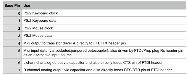
A breakout accessory for PS/2 would only need 4 pins for keyboard and mouse use. I wonder what the other 4 IO could be used for? What would make sense to do with them? Maybe some optional audio line outs if you choose to use the HDMI breakout instead of the A/V accessory, or a header pinned for a serial FTDI cable (it could probably support both)? A single wide accessory could fit one of those double stacked mini-din6 connectors and a 6 pin header behind it for an FTDI cable (and/or a prop-plug header too).
Provided there's a 5 V power-source available, why not MIDI?
Good choice for two pins but the midi connector is rather bulky unless you breakout only to a pin header. May need a slightly bigger board with an optocoupler or socket for one if optional. Something wired up like this might make a handy board that could be used for lots of things...serial, audio, kbm, midi, take your pick.
Another way to go is to have a separate midi + audio board with 2 x midi pins, 4 x i2s digital dac pins, 2 analog audio pins, and keep the other one for serial + KBM.
A good idea. What is FTDI for in this?
Well you could breakout a second serial port via an FTDI cable or as a logic level UART to something else like a RasPi etc - It's sometimes handy to have another separate way to have the P2 talk outside of the main USB or prop plug on board. It lets you send out to a separate RS232 transceiver board too if required. I'm just proposing to wire in the 6 pin header.
It seems to have P2-related previous works, and also external references, so as to avoid (re-)starting from scratch:
https://forums.parallax.com/discussion/171997/p2-midi
https://learn.sparkfun.com/tutorials/midi-tutorial/all
And sure, the "master" source:
https://midi.org/
Full specs and guidance can be found there, for free; just a simple registering proccess, and you're in.
The most recent specs have a lot to say about using 5 V, or even 3.3 V power to drive the circuits, and also many words of caution on EMC, grounding (loops and the like), and non-conforming hardware that can be source of many (and usual) headaches.
Indeed. I've got a Johnny Mac, so I'll breadboard it for my ow
Yes, indeed. I don't know how to program a smart pin, but PS/2 keyboard protocol is stupid simple. I would think a smart pin could do it. Ben Eater explains:
I'm sure @pik33 would agree with you on that one. I do also as MIDI doesn't seem to be covered by any other accessory. Does the P2 drive high enough for MIDI, or are level shifters needed? If not, it the board would just be connectors, traces and solder. (oh, and resistors too)
I would rather it NOT have a PropPlug connector but rather one for the cheaper 4/$10 FTDI boards (https://www.amazon.com/FT232RL-Serial-Converter-Adapter-Arduino/dp/B07XF2SLQ1/ref=sr_1_6?crid=3A16YD93CD5TV&keywords=ftdi+usb+to+serial&qid=1657408052&sprefix=ftdi,aps,177&sr=8-6) unless Parallax is going to make the thing (it might be profitable with enough demand). I proposed it in the p2-MIDI thread. I wonder how much interest there is. The PS/2 ports could be quite handy for Console Emulation also.
Another idea for an accessory board. 2 PS/2 ports and 2 Joy ports (using resistors for analog input, is there a standard for this?). The 2 DB9's could poke out on the left and right and 2 PS/2 ports on the end.
This probably would be the best Console Emulation too. That brings up another question, does the https://www.ebay.com/sch/i.html?_from=R40&_trksid=p2047675.m570.l1313&_nkw=New+Retro-Bit+Official+Sega+Genesis+Controller+6-Button&_sacat=0 have standard pinouts? How are the extra 5 buttons handled?
Thanks,
Doug
Not really a single standard. There were so many different joystick interfaces...which would you target?
Many joystick controllers nowadays use USB which can make thing more difficult to interface to in your own projects, although the USB driver for P2 has been recently modified to support some gamepads by macca and Wuerfel_21, which is very helpful.
My stronggest advice is for you to take a look at the freely-available MIDI specs, and the more examples you can find, before trying it.
The following page shows a suggested interface circuit (MIDI 1.0 Electrical Specification Update [2014]), and the link to it can be accessed without registration:
https://midi.org/specifications-old/item/midi-din-electrical-specification
When it comes to 3.3V-powered interfaces, it shows very low values for the involved resistors at the "OUT" and "THRU" circuit.
Since P2 pin-drivers stronggest settings results in ~18 Ohm of series resistance, any extra current-limiting resistor will be limited to just a few Ohms, which seems "very dangerous", in the sense of protecting the output-pins from "your most beloved processor, ever", just to say a minimum.
The "IN" circuit will also require some toughtfull decisions, since it'll depend on the chosen opto coupler requirements. Without it (opto) your board can be part of a huge ground loop; in general, not a really good thing to deal with...
But the board(s) is(are) yours (and so does the money); at least, you have way more than 50 free pins for "experimenting"...
Those two are the same and was the norm throughout the 1980's. Many cheap joysticks were built for the 9-pin plug, but the market vanished when 3D graphics and joypads arrived.
I power my 5V based (Arduino type) breakout from 3V3 and it works OK for MIDI In. However I didn't test MIDI Out in this. We can always use a logic level shifter chip, they are cheap, and a 5V voltage is available on the 12-pin connector
All this optocoupler stuff is done to not connect grounds of the music stuff. For a desktop setup however I already have much worse ground loops (and it is hearable ) The P2 is connected to PC USB, then P2 audio is connected to the mixer along with a PC audio, and what is the most evil is the HDMI switch, so I use another small 15" TV for a P2. Adding a (one) MIDI controller keyboard without an optoisolator while the same controller is connected to a PC via USB will add 4th loop.
So in reality the P2 based synth module should (1) have this MIDI optoisolator on board, (2) have its own display, maybe even a touch controlled one, (3) the output audio transformer can also be useful.
I already made an interface for Atari type joystick, which was the 80's standard, Atari8, ST, Amiga and C64 used it. 2 pins used, one for direction, one for buttons, several resistors and ADC pin mode. Maybe I should try this with NeoYume or MegaYume But then, Ataris also uses something called paddle, which is in reality a potentiometer, which can be easily created at home, there are objects in Thingiverse ready. These NeoGeo and MegaDrive consoles use controllers with a lot of buttons, so maybe the solution with a PS2, audio and MIDI on one bank and 2 multicontroller interface on another can be better.
I ordered some parts for a SNES interface (really just needs two N mosfets to boost latch and clock to 5V and a bunch of resistors). I have a semi-unfinished arcade stick left over from an old project, which I wired up with shift registers at some point. That'll be pretty neat ig.
Please note that in case of P2 Edge Mini Breakout Board, and P2 Edge Module Breadboard (AKA, JonnyMac), there are two 12-pin accessory headers in each product where the 5V output isn't even available:
at J204 (both boards), pin 11 is unconnected;
at J205 (Mini Breakout, 64019) and J208 (JonnyMac, 64020), pin 11 is directly connected to P2_RESN.
Just to keep it in mind:
At both boards J204 is the one (connector) that brougths P2_IO[31:24], VIO_24_31, and GND.
As for J205 (Mini Breakout), and J208 (JonnyMac), there are P2_IO[63:56], P2-RESN, VIO_56_63, and GND.
Some useful references can be found at each board Schematics/User-Manuals, and:
https://forums.parallax.com/discussion/comment/1538575/#Comment_1538575
Hope it helps (to just don't "fry") any/many bit(s).
The 5V output boost circuit I use for SNES outputs looks like this. I guess the drive through the 10K resistor is a bit weak, but this works at pretty absurd speeds (for SNES clocking, anyways). This may be the smallest possible circuit that accomplishes this.
For inputs it's just 3.3k inline resistors, as per Chip's recommendation for P1. Is that good for P2 too?
You can probably go direct out. 3.3 Volts for a logic high should work. You could use the 10 k resistors for incoming. If that's enough then it'll be less stress than 3.3 k resistors.
No it doesn't. The shift registers are CD4021, which need a 3.5V high level.