

25nS pulse on a P1
 Jeffrey Kane
Posts: 48
Jeffrey Kane
Posts: 48
Hello,
many years ago I went down this road, but maybe things have changed and it would be possible
I'm sending bits to a specific pin using PASM

which works perfect, as you can see, I can send any bit pattern I want,
the example below is AAAAAAAA
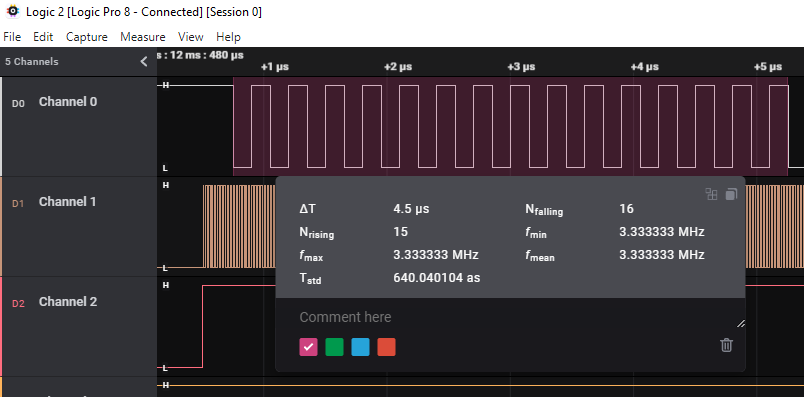
each pulse is 152 nS
so there is nothing wrong, works as designed, but is there a way to get a smaller pulse width? assuming that the patterns can be selected by the user. I have a 40Mhz oscillator on the board, nothing to do with the prop, but I do have time between each pulse of 250uS, so I could load a bit pattern, clock the pattern to the external oscillator. I'm trying to avoid an FPGA, and I know the P2 could do this easily, except my form factors are Prop mini or Prop flip, and I don't think the P2 has these yet, could be wrong.
regards
Jeff
Comments
Look up the waitvid opcode. Used in conjunction with a counter PLL, you can send fast bit patterns that need PASM attention only every 32 bits.
-Phil
+1 for waitvid, but there's another alternative: Set up one of CTRA/CTRB for NCO mode, set FRQA/FRQB to zero. Now, bit 31 of PHSA/PHSB will be output onto the configured pin, so you can write your loop like this:
      mov phsa, pattern
:loop shl phsa,#1
      djnz count,#:loop
You can obviously unroll this to make it even smaller by just repeating
shl phsa,#1.Hello, I used the FRQ and CTR suggestion
but I got no output from the loop, everything compiles fine and loads into the prop. not sure if the FRQA/B has to be cleared on every use of the output, and I set the CTR to 1111 => pin 15, my output pin. I tried to find more doc on FRQA/B but there is one example,
FRQA = $00001AFF, I assume that is presetting a counter value, maybe?
regards
Jeff
Did you remember to set dira for the pin to an output?
-Phil
Yes, it always has been set to output, pin 15 is the pin I usually use in the example posted above
but here are the settings I am using currently
I also tried pin 2, like the example in the reference manual under assembler ctra
but the LA shows no output for either pin 15 or pin2,
if I switch it back to this
I get output of the original 152 nS pulse width
regards
Jeff
I think you're missing a zero somewhere in there (the Manual also has the typo, so I guess it's not your bad)
ok, I now have the right number of bits for CTRA/B
no change on the output
Where do you set frqa to a non-zero value?
Oh, wait, I see what you're trying to do with phsa. But you can't do that. phsa can't be the destination of a read-modify-write instruction. Why not just set frqa to a non-zero value and let the counter do its work?
-Phil
No, that does work.
Also, make sure the OUTA bit for Pin 15 is low. The different output circuits (OUTA, counters, video) are OR-ed together, so if OUTA is high the counter output is ignored.
From the manual:
"Beware that doing a read-modify-write instruction on PHS, like "ADD PHSA, #1", will cause the last-written value to be used as the destination operand input, rather than the current accumulation."
Exactly. And if FRQ is zero, that doesn't matter.
That is kind of an edge case, isn't it? The clock is enabled and "running" -- which in most cases would preclude RMW instructions -- but not counting.")
I still don't quite see the advantage in doing it this way, when the counter itself could be doing more of the heavy lifting.
-Phil
Not really. There isn't ever an issue writing PHS while the counter is active.
This (or,rather, the unrolled variant) is the fastest non-waitvid way of shifting out data.
I will check this tomorrow
"Also, make sure the OUTA bit for Pin 15 is low. The different output circuits (OUTA, counters, video) are OR-ed together, so if OUTA is high the counter output is ignored.",
Is it possible that I'm doing things in the wrong order
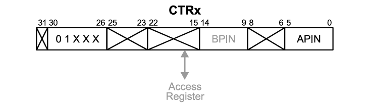
CTRA
FRQA
DIRA
OUTA
and then set PSHA to the data to be serialized
mov PSHA,test_bits 'AAAAAAAA
and then the loop thru data to send output to the pin 15
:Pin_Looper SHL PSHA,#1
DJNZ count, #:Pin_Looper
Jeff
True, but in the OP's case the shifted-out data is just a square wave, which the counter could handle by itself.
-Phil
When referring to the phsx registers, one must be very precise about the word "writing", without over-generalizing. Yes, you can always write to PHSx, and the result will be reflected in both the counter register and its shadow register. However, whenever phsx is read when it's a destination register, as in a read-modify-write situation, the value read comes from the shadow register, not the counter register itself. And the shadow register contains the last value written to it -- not the value in the counter register.
OP's code works only because frqa is zero, and phsa never increments on its own. Because of that, phsa's counter and shadow registers are always equal. So the read-modify-write appears to shift the counter register when, in fact, its source before the shift is the shadow register, which it then shifts and writes back to both the counter register and the shadow register.
The same caveat must be observed when writing phsx to hub memory. This won't work, as one might expect:
because it writes the contents of the shadow register, not the counter register.
Even the Propeller manual is over-broad in its explanation, since it neglects exceptional edge cases, such as the one in this thread:
"Note that in Propeller Assembly, the PHSA and PHSB registers cannot be used in a read-modify-write operation in the destination field of an instruction. Instead, separate read, modify, and write operations (instructions) must be performed."
-Phil
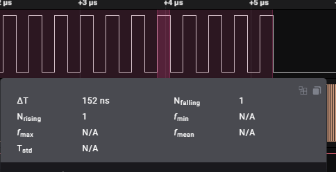
Hello, well It seems to work, pulling the pin low before the loop seemed to make the difference, so here is what is working and the time of a pulse. this way of doing it reduced the pulse width from 152nS to 100nS,
There is a comment in this thread that says "You can obviously unroll this to make it even smaller by just repeating shl phsa,#1." which I think means shl phsa,#1 shl phsa,#1 multiple times, when I do that I get 52 ns pulse width, but multiples give me multiples of 52 ns not less each time I add one.
anyway, these are the settings to get the phsa to pulse with random input, I still would like to go faster, i.e. smaller pulse widths. (if possible)
for this test this is the data I am sending
and this is the output from the analyzer
the quick reference guide says that a djnz instruction take 4 clocks cycles, as does a SHL instruction, total of 8, probably why when I stacked the shl instructions I got basically 1/2 of 100 ns => 52 ns.
so far I can get 50nS with random data, by doing multiples of shl
Jeff
Of course it's possible! Use waitvid.")
-Phil
I'm reminded of clever tricks that went into the Prop 1 SD card interface, FSRW and safe_spi.spin. That was code from @lonesock, with ideas from @rokicki, @kuroneko and others. As with the suggestion here, it ended up with 8 successive rol phsa for byte writes. There is code for reading too, at two instructions per bit. One idea, I think from @kuroneko, ultimately commented out, tried for 1 instruction per bit, using ctra A&B mode and a succession of 8 shr frqa,#1. With A being the clock line to the SD card (driven by frqb) and B the SD data line. That one is a real brain teaser.