For the 360 MHz case, first step is to precisely measure the frequency. I use my digital scope but anything with a frequency counter will do. I config a smartpin to P_NCO_FREQ with sysclock/1000 frequency output. This will produce a rock solid 360 kHz when the PLL is not self-limiting. Stick this line in at init time:
pinstart( 56, P_NCO_FREQ | P_OE, 500, $8000_0000 ) ' pin 56 output frequency of sysclock/1000
@RossH said:
I also tried putting the board in the freezer for a while yesterday, which did seem to make a difference - it wouldn't work till it warmed up, then it began to work quite reliably for a while.
So - how much temperature change should be necessary to change the Props behaviour? And does it make any sense that it seems to work better when is warmer?
Won't be because of PLL self-limiting then. The colder temps will be stable. Will need well over 50 degC die temp for self-limiting to fall below 360 MHz.
I also tried putting the board in the freezer for a while yesterday, which did seem to make a difference - it wouldn't work till it warmed up, ...
Possibly due to condensation, which will happen when the temperature of the board is below the dew point of the warmer environment. I'm not sure this would cause any actual shorts, though, since condensation is theoretically pure water and non-conductive. But you might try testing it while it's in the freezer.
Done some looking at my older testing - had almost forgotten about it ... Self-limiting kicks in for 360 MHz with die temperature up at about 90 degC for RevB/C silicon. However, the thermal gradient under load means the thermal pad is more likely at about 70 degC.
Here's the full table from that earlier testing: (Excuse the formatting, I used tabs and this newer forum software treats them poorly)
RevB glob-top.  Temperatures are in degree Centigrade.
*  MHz is frequency of the PLL's VCO before the XDIVP divider
*  Thermocouple is soldered on Eval Board underside, middle of Prop2
*  /1 and /20 are the XDIVP dividers tested
===============================================
    MHz /1(*)   /1  /20 /20 u   /20 d   /1 u
================================================================
    320
    330 122         137 135
    340 106         120 118
    350 92  94.5        106 103
    360 78  80.5    90.5    93  89
    370 65  67.5    77  80  75.5
    380 53  55.5    65  67  63
    390 41  44  52.5    56  51.5
    400 30  32.5    41.5    45  40
    410 19  22  30      30
    420 9   11  20      19
    430 -1  1   10      9   0.8
    440         0   0.5 -0.5
===============================================
(*) Cog0 idling, using WAITX, with other cogs stopped.
Standard test is all eight cogs idling.

U - Rising ambient temperature with Eval Board facing up
D - Falling ambient temperature with Eval Board facing up
u - Rising ambient temperature with Eval Board facing down
d - Falling ambient temperature with Eval Board facing down
I didn't try yet. Meanwhile, as I added several instructions to the driver loop, the problem disappeared.
The debugging priorities, if the problem returns, are
(1) to search and find the bug in my code
(2) to isolate a problem using the simplest code possible
(3) try changing the frequency and the DAC clocks cout
(4) check if there is something related with waitse1 and loop cycles count.
I still hope that the bug in my code is the case. I wrote a lot of things on a P2 and this is the first time I encountered something like this.
would the HDMI absorb these jitters?
I use HDMI and high clocked P2 (up to 357 MHz) - I didn't notice anything bad. HDMI should absorb any jitter until is too bad to handle.
Okay, just found what I presume is the low-level SD bit-bash loop in the file target_p2/Catalina_SD_Plugin.spin2:
.nextbit        rol     dataout,          #1        wc  ' \ prepare output bit (DI=0/1)..
                outl    #_SD_CK                         ' | CLK=0  (already 0 first time)
                outc    #_SD_DI                         ' / write output bit: output on CLK falling edge
                waitx   #2                              ' |   setup time to be safe
                outh    #_SD_CK                         ' \ CLK=1
                waitx   #3                              ' |   setup time to be safe
                testp   #_SD_DO                     wc  ' | read input bit:   sample on CLK rising edge
                rcl     reply,            #1            ' / accum DO input bits
                djnz    bitscnt,          #.nextbit     '   8/32 bits?
        _RET_   outl    #_SD_CK                         ' CLK=0 on exit
So, the allowed lag, from outgoing low clock edge to TESTP receiving data, is 15 sysclock ticks. That should be enough but maybe it's not quite. I know my 14 ticks lag allowance is fine to about 320 MHz but the SPI mode R-C curve on the SD's DO pin is really not nice. The Sandisk I have is the worst at this.
Therefore, my guess is the 360 MHz issue is likely large amounts of SD read data corruption from lag effect. More compensation on the WAITXs should fix that.
It's possible there is an issue with SPI clock polarity in general. I noted both Cluso and Mike Green used idle high - ie: SPI Clock Mode 3 instead of Mode 0. I flipped Eric's to idle high instead of low for reliable operation. My routines supported idle low but none of my routines actually would work with idle low. I didn't investigate exactly why. Most likely due to an implied clock phase discrepancy.
On that note, the clock phase in the above routine looks to be more like Mode 3 rather than Mode 0, except it's idling low like Mode 1 would.
EDIT: Oh, I see, the first OUTL #_SD_CK doesn't change the clock pin. It's already low, as stated in the comments. And if Mode 0 is functioning then the data bit is already present at the input.
Okay, just found what I presume is the low-level SD bit-bash loop in the file target_p2/Catalina_SD_Plugin.spin2:
Catalina's SD Card plugin is cribbed from the Propeller's SD card boot code. But I have recently discovered there are lots of SD cards of various sizes and brands that it does not seem to work well with (I am not blaming the Propeller code - it is quite likely to be my fault and I have not understood it or incorporated it correctly).
However, I think I am going to give up on finding this 180Mhz problem - every time I think I am getting close to understanding it, it changes behaviour. I don't think I will be able to track it down from this example, so I will wait for another example to show up that might be more amendable to analysis. Catalina appears to work fine at every other clock speed I have tried, so the next release will simply warn users to be aware of this issue and recommend they use a clock speed other than 180Mhz if possible.
Instead, I clearly need to spend some time improving Catalina's SD card plugin. I had no idea how limited it was until I started messing about with this problem, and (as a consequence) started trying to buy some more SD cards to use. The current plugin only seems to work reliably for SD cards of size 8GB or smaller, and even then only with specific brands of card. But my local electronics shop says they cannot even source such small SD cards any more
@RossH said:
Catalina's SD Card plugin is cribbed from the Propeller's SD card boot code.
Oh, as in Cluso's code? Huh, I'd thought I'd seen examples from him that used clock idle high. There was definitely someone else that had idle high. The SD simplified specs themselves aren't clear on it at all. I presume the full specs cover it.
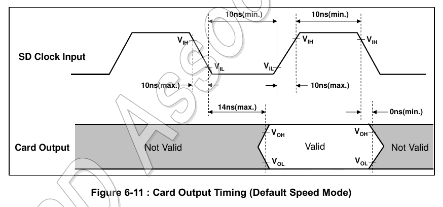
7.5 SPI Bus Timing Diagrams
This section is a blank in the Simplified Specification.
Then again, if the following is representative of the missing diagram then having it included wouldn't help at all since it only really covers setup and hold:
@evanh said:
Therefore, my guess is the 360 MHz issue is likely large amounts of SD read data corruption from lag effect. More compensation on the WAITXs should fix that.
No, the 360 MHz issue won't be due to lag effects ... after further testing, I'll double down on the earlier comment about unreliable cogs or I/O when running even close to the self-limiting PLL frequency. Basically, that safeguard isn't sufficient for reliability.
EDIT: More testing ... I'll go one further and state it's explicitly a limitation of Prop2's pin input response. Cogs and pin output seem to be fine. I'm not getting any crashes, just data read errors - even when SPI clock is way low with lots of space for lag. Rechecking the data on the SD card at a lower sysclock has no errors.
PS: In my case I need at least 380 MHz sysclock to reliably trigger this condition. That's close enough for me to believe rare cases may occur at 360 MHz still. Or that a higher processing burden may lower the frequency threshold. Certainly a higher ambient temperature has a real impact on lowering the threshold frequency.
380 is the place where P2 starts to give up, over 380 it starts to randomly crash. As an PC overclocker I used the rule - go up until it starts to crash, then go 5% lower. For P2 it is something about 360 MHz. What I used for P2 was 354, for the player, when it didn't use PSRAM, and it was stable (hours of work with at least 3 different P2s).
I'll posit the self-limiting PLL protects the cogs, ie: they don't flat crash on the spot, but pin input errors occur. If program code gets loaded at that frequency then that code will be corrupt from the loading process.
EDIT: There might be something more to it ... something fishy with the corrupt data - it's not random, it's always bit1 (second last) of a longword, it's always set in error, and it's rare. May be as little as one bit per 100 blocks, although this is likely dependant on how close the PLL frequency limit is.
@evanh said:
I'll posit the self-limiting PLL protects the cogs, ie: they don't flat crash on the spot, but pin input errors occur. If program code gets loaded at that frequency then that code will be corrupt from the loading process.
EDIT: There might be something more to it ... something fishy with the corrupt data - it's not random, it's always bit1 (second last) of a longword, it's always set in error, and it's rare. May be as little as one bit per 100 blocks, although this is likely dependant on how close the PLL frequency limit is.
At least to my elderly nose, what you're describing (MTBF-related input error numbers/rates that worsen as clock speed increases, up to the point they become almost "stuck", or deterministic (the errors themselves)) smells too much like METASTABILITY.
The "stuck" bit 1 is simply the most "deterministic-failing-one", at the given block; many others can cohexist, at the same group, or elsewhere, subjected to their own individual conditions/ranges of "bad-behaviour-triggering", starting from any clock frequency higher than the maximum specc'd by Onsemi as the maximum for the current P2 silicon.
Please note that metastability tends to translate to delayed assertion of "valid" output(s), onto the affected flip-flop(s)/registers(s). When/where a series of chainned flip-flops is involved, any one of them can be the cause of random events of failure, each one being subjected to its own individual PVT and also any "local noise" conditions it is subjected to.
In the present case, where only the resulting output of the chain can be observed by the Cog/Streamer, one can't notice wich one of them is in fault, untill at least one "stucks" (can even be more than one; it only depends on positional arrangement, and local PVT conditions).
Also note that, in this case, there are possibly multiple events leading to the "same" bad-result, due to the cohexistence of VDD-biased, and also VIO-biased logic, in the same chain.
@Yanomani said:
At least to my elderly nose, what you're describing (MTBF-related input error numbers/rates that worsen as clock speed increases, up to the point they become almost "stuck", or deterministic (the errors themselves)) smells too much like METASTABILITY.
Thanks. It surprises me the stuck bit didn't move around in the smartpin's shifter/buffer. I was thinking the cause would've been in the early input stages. But this behaviour is suggesting the most sensitive area is between the smartpins and cogs. Which suggests an equivalent test using bit-bashed I/O will behave quite differently.
Thanks. It surprises me the stuck bit didn't move around in the smartpin's shifter/buffer. I was thinking the cause would've been in the early input stages. But this behaviour is suggesting the most sensitive area is between the smartpins and cogs. Which suggests an equivalent test using bit-bashed I/O will behave quite differently.
You're always welcome!
Bit-bashing can really point you to somewhere; the higher the number of flip-flops/latches/registers involved, the better. Stepping from VIO-domain towards VDD-domain, and also varying the number of register-alike structures (by resorting to clocked/unclocked I/O) can help fingering a culprit.
Perhaps including some other "unused" Streamers as "voyeurs", by interleaving/interspersing their read-accesses within the margins allowed by the relatively low-speed I/O clock/data bits (as compared to the intrinsic high-speed Sysclk), and comparing their respective read-buffers (perhaps circular???) to the "main one" (as seen by the bit-bashing Cog, or a "free" neighboring-one), can lead to some meaningfull delay-pattern, that can show how far one can get always-error-free operation.
Sure, more power consumption is a path for less safespan, where it comes for noise-free bias voltage and temperature raise, and this can worsen the results a bit, but we are looking for a furtive entity, so, perhaps, the more flashlights, the better.
You know, it's hard to me to try fitting the whole landscape of possibilities, within my "neuron-based" instrument...
Hi Ross,
As I am not aware, that this idea has already been discussed here: Could you execute some dummy code in an additional cog?
It might be helpful to see, if heating the chip has influence or if the compiler or the download software is influencing things.
Are there any magic numbers active in the setup?
For me it seems hard to believe, that a certain clock frequency directly leads to problems. So I would perhaps try to go the Forth way: Cut down the code into smaller slices, which can be tested more easily?
Good luck! Christof
The 180 MHz issue is unlikely to be the same issue, it won't be heating related. Ross has even said the 360+ MHz symptoms are different from the 180 MHz symptoms.
EDIT: I guess it's possible there is two issues up at 360 MHz. One related to 180 MHz and also the overclocking limit.
@"Christof Eb." said:
As I am not aware, that this idea has already been discussed here: Could you execute some dummy code in an additional cog?
It might be helpful to see, if heating the chip has influence or if the compiler or the download software is influencing things.
Not easy. Almost any change made to the program makes the problem go away, which is what makes diagnosis so tricky. I have to be careful not to upset the size, layout, alignment or timing of any of the existing code, or the problem can simply vanish. This can make you think you have found a clue when in fact you have not. Loading another cog would almost certainly do this.
@evanh said:
EDIT: I guess it's possible there is two issues up at 360 MHz. One related to 180 MHz and also the overclocking limit.
Yes, I now think that I am seeing a consequence of the interaction of multiple issues. One may be related to the SD Card, the other may be related to timing. If I can sort out the SD card issue the other one might become easier to solve, but it will also make this particular instance vanish and I will have to wait for another example to show up.
Could one of you guys point me/show me the piece of code that configures the pins involved in those transactions you've been mentioning so far?
I'm particularly interested in the way those lines are being terminated inside P2, because I remember @evanh mentioning ugly data waveforms, coming from SD card DAT0/MISO towards P2_IO58.
At least all EVAL boards (Rev A thru C) have a 240R resistor in series, between IO58 and DAT0/MISO, and that can pose a threat to any capacitive charge/discharge, partially justifying the weird waveforms observed.
I understand the presence of the resistor as a means of mitigating any conflict between simultaneously driven outputs, so, perhaps, if the internal termination method currently selected (P2-side) is resistive, changing it to current-mode (~100uA???) can clean that signal a bit, enough to speed-up its level resolution, which could also help, in the case of any possible metastability.
Even if one needs to resort to dual simultaneous termination methods (e.g., resistive towards 3.3V, and current towards GND, or vice-versa), that option is also achievable, and valid, as provided by the two groups of control bits involved.
Both configs simultaneously at current-mode is also valid, and will loselly resemble a DDR-bus being kept at VIO/2, in order to mitigate noise, and also speed-up logic level resolution (AKA capacitive discharge).
I vaguely remember of a specific command of SD cards (ACMD42?), meant to disable/enable internal termination (inside the card itself), but I believe it affects only the CMD/MOSI line, though I'm not sure bout it.
I'm also not sure if all card brands/models rely on the same internal termination methods (if any/active) during all possible operational modes, and even during the evolution of data transfer sessions, within any specific mode, so this can also help explain why some brands/models are so "picky", as compared to the "easier" ones.
Here's the whole plug-in file from Catalina. It's bit-bashed at sysclock/25 so is not going to be the same corruption as I was getting with the smartpins in FlexC at 380 MHz.
EDIT: Also, SD cards operating in SPI mode don't support anything above standard speed (25 MHz SPI clock). They ignore all commands for adjusting drive strength.
@Yanomani said:
At least all EVAL boards (Rev A thru C) have a 240R resistor in series, between IO58 and DAT0/MISO, and that can pose a threat to any capacitive charge/discharge, partially justifying the weird waveforms observed.
Hope It helps a bit...
Oh, huh, I overlooked that previously. It explains the R-C curve for sure. But isn't anything to do with the smartpin corruption at 380 MHz sysclock.
@evanh said:
Here's the whole plug-in file from Catalina. It's bit-bashed at sysclock/25 so is not going to be the same corruption as I was getting with the smartpins in FlexC at 380 MHz.
EDIT: Also, SD cards operating in SPI mode don't support anything above standard speed (25 MHz SPI clock). They ignore all commands for adjusting drive strength.
Thank you so much @evanh, I'll try to understand it, as soon as I come back from my humble "cannibal mittagessen"
Oh, huh, I overlooked that previously. It explains the R-C curve for sure. But isn't anything to do with the smartpin corruption at 380 MHz sysclock.
If my gut/nose feeling about metastability has anything to do whith it, then it can even apply, because there is chance for metastability to occur wherever clock and data transitions "almost" overlap in time (within the narrow limits of setup and hold times).
So, a poorly defined (or in the middle of a change) logic level can be wrongly interpreted by the receiving peer (P2), then forwarded "as is", throughout the whole chain of consecutive flip-flop-alike structures.
@Yanomani said:
So, a poorly defined (or in the middle of a change) logic level can be wrongly interpreted by the receiving peer (P2), then forwarded "as is", throughout the whole chain of consecutive flip-flop-alike structures.
Nah, DO signal has lots of settle time with sysclock/25. Especially at 180 MHz sysclock.
EDIT: Same for 380 MHz where metastability is of concern. The pin input isn't going to be the issue. Even the symptoms back this up - the position of the stuck bit, in the read word from the smartpin, is constant.
Ross, that's something to be wary of for all designs that use the crystal oscillator. Keep sharp switching clear of those four pins. I think, the more capacitive the circuit, the worse the crystal instability becomes. It's only encountered by FAST output drive too. Anything weaker, including DAC modes, are fine.
@Yanomani said:
So, a poorly defined (or in the middle of a change) logic level can be wrongly interpreted by the receiving peer (P2), then forwarded "as is", throughout the whole chain of consecutive flip-flop-alike structures.
Nah, DO signal has lots of settle time with sysclock/25. Especially at 180 MHz sysclock.
EDIT: Same for 380 MHz where metastability is of concern. The pin input isn't going to be the issue. Even the symptoms back this up - the position of the stuck bit, in the read word from the smartpin, is constant.
Eek! I get the same symptom when using bit-bashed path! Always a sporadic bit1 set of a 32-bit word read back from the SD card - My bit-bashed code path shifts bits in/out of a full 32-bit register unless there is less than 32 bits left of the transfer. There's no particular recurring locations, just the bit position is always bit1.
EDIT: Ah, but there might be a common bit sequence in the data ... nope, I'm getting every one of the eight combinations for the last four bits.
It completely defies explanation! The only explanation is the cog is what's failing. It must be very close to crashing. EDIT2: And it's true that it crashes at 390 MHz so that must be it. The self-limiting PLL doesn't save things.
If the exact same symptoms were happening with a Hyperram, or Psram, I'll sure agree with you that the most likely cause would be a Cog failure, because those devices rely on state machines, totally "enslaved" to their clock inputs; they have no choice, other than forwarding the byte/nibble they have inside their intermendiate registers, independently if they are "steady", or "almost ready" for transfer.
The structure of command/parameter passing happens at the beggining of the access-phase, and them there are the forcefull delays, before the data-transfer-phase starts, thus there are even more opportunities to sync its beggining.
But SD cards (and also MMC ones) don't use such a "hardware-crafted" state machine; they rely upon "software-crafted-ones", since there is a microcontroller intermediating the transfers between the "master" (P2), and the device.
We don't really know (no access to that information) how wide are the internal shift registers (SD-side), nor how the microcontroller operates them (the sequence of loading the first byte (possibly), or any of the next ones, involved in the read-commands being executed.
If you take a look at P2 synchronous-mode transfers (I know you know about it), you'll notice that the first bit of the first data-item is directly forwarded toward the output pin, as soon as the register is loaded from a Cog, ready to be transfered when an external clock shows the expected transition, and only them, the hardware advances to the next one, and so on, till the last bit.
Then, if the buffer has been loaded with a next data item, operation will continue, as paced by the clock input, till the last one.
So, perhaps, even if one calculates the right number of Sysclks, in order to input each bit at the maximum pace, perhaps (and it's a huge perhaps here), if the inter-symbol timming can be adjusted, at least at that region under scope, in order to widen the interval between clocks (or, more preciselly, between the specific clock borders that signal the SD card that P2 is ready to receive the next bit).
This can be limited to the top-higher Sysclk rates, despite there will be the need to use more code space to do it that way, but if it solves the problem, till the very maximum Sysclk, well, perhaps it worth pursuing it.> @evanh said:
There is no way for the 380 MHz glitches to be external to the prop2. Or even in the I/O pad-ring. I had already tried changing Schmitt and registration modes much earlier, btw. The fact it produces a bit1 only glitch then excludes all serial stages from consideration.
The only question was where internally, in the synthesised logic. I was expecting to see something different with the bit-bashed vs smartpin execution paths, but the behaviour difference was zero. Got exactly the same symptoms.
Huh, hubexec affects it ... hmmm, looks like it might be hub timing, FIFO putting pressure on the WRLONG. I can eliminate the glitch simply by moving the receiver code into cogRAM. That would help explain the rarity of the glitch.
At any rate it's clearly due to overclocking just being too high.
EDIT2: Problem now is the bit-bashed code path was already cogexec ... ah, it uses the FIFO instead of WRLONG. Changing the smartpins routine to also use the FIFO reproduces the glitch again.
So, the weak spot is likely in the egg-beater region. Other cogs may have different outcomes.
Heh, dig out the old pasm-only test routines. They can live 100% in cogRAM. Job for tomorrow though ...
@evanh said:
There is no way for the 380 MHz glitches to be external to the prop2. Or even in the I/O pad-ring. I had already tried changing Schmitt and registration modes much earlier, btw. The fact it produces a bit1 only glitch then excludes all serial stages from consideration.
The only question was where internally, in the synthesised logic. I was expecting to see something different with the bit-bashed vs smartpin execution paths, but the behaviour difference was zero. Got exactly the same symptoms.
I am confused: Is there any relationship between a problem occuring at exactly 180MHz and the symptoms which appear at 380MHz, very much above the rated frequency?
Nope, no chance. The 380 MHz example is one possible reason for what happens at 360 MHz - Which Ross has also listed as problematic. I've just been following this possibility through.
There are various cases, throughout the Prop2 forum, where somebody is testing code up at or near 360 MHz but we've never really understood reliability in that area. The PLL self-limiting was setup with revB silicon but hasn't been verified to protect reliable code execution.
The 180 MHz issue has been sidelined until either another idea comes to mind or Ross can find a shareable case example. Mainly the latter.


Comments
For the 360 MHz case, first step is to precisely measure the frequency. I use my digital scope but anything with a frequency counter will do. I config a smartpin to P_NCO_FREQ with sysclock/1000 frequency output. This will produce a rock solid 360 kHz when the PLL is not self-limiting. Stick this line in at init time:
Won't be because of PLL self-limiting then. The colder temps will be stable. Will need well over 50 degC die temp for self-limiting to fall below 360 MHz.
Possibly due to condensation, which will happen when the temperature of the board is below the dew point of the warmer environment. I'm not sure this would cause any actual shorts, though, since condensation is theoretically pure water and non-conductive. But you might try testing it while it's in the freezer.
-Phil
Done some looking at my older testing - had almost forgotten about it ... Self-limiting kicks in for 360 MHz with die temperature up at about 90 degC for RevB/C silicon. However, the thermal gradient under load means the thermal pad is more likely at about 70 degC.
Here's the full table from that earlier testing: (Excuse the formatting, I used tabs and this newer forum software treats them poorly)
RevB glob-top. Temperatures are in degree Centigrade. * MHz is frequency of the PLL's VCO before the XDIVP divider * Thermocouple is soldered on Eval Board underside, middle of Prop2 * /1 and /20 are the XDIVP dividers tested =============================================== MHz /1(*) /1 /20 /20 u /20 d /1 u ================================================================ 320 330 122 137 135 340 106 120 118 350 92 94.5 106 103 360 78 80.5 90.5 93 89 370 65 67.5 77 80 75.5 380 53 55.5 65 67 63 390 41 44 52.5 56 51.5 400 30 32.5 41.5 45 40 410 19 22 30 30 420 9 11 20 19 430 -1 1 10 9 0.8 440 0 0.5 -0.5 =============================================== (*) Cog0 idling, using WAITX, with other cogs stopped. Standard test is all eight cogs idling. U - Rising ambient temperature with Eval Board facing up D - Falling ambient temperature with Eval Board facing up u - Rising ambient temperature with Eval Board facing down d - Falling ambient temperature with Eval Board facing downI didn't try yet. Meanwhile, as I added several instructions to the driver loop, the problem disappeared.
The debugging priorities, if the problem returns, are
(1) to search and find the bug in my code
(2) to isolate a problem using the simplest code possible
(3) try changing the frequency and the DAC clocks cout
(4) check if there is something related with waitse1 and loop cycles count.
I still hope that the bug in my code is the case. I wrote a lot of things on a P2 and this is the first time I encountered something like this.
I use HDMI and high clocked P2 (up to 357 MHz) - I didn't notice anything bad. HDMI should absorb any jitter until is too bad to handle.
Okay, just found what I presume is the low-level SD bit-bash loop in the file
target_p2/Catalina_SD_Plugin.spin2:.nextbit rol dataout, #1 wc ' \ prepare output bit (DI=0/1).. outl #_SD_CK ' | CLK=0 (already 0 first time) outc #_SD_DI ' / write output bit: output on CLK falling edge waitx #2 ' | setup time to be safe outh #_SD_CK ' \ CLK=1 waitx #3 ' | setup time to be safe testp #_SD_DO wc ' | read input bit: sample on CLK rising edge rcl reply, #1 ' / accum DO input bits djnz bitscnt, #.nextbit ' 8/32 bits? _RET_ outl #_SD_CK ' CLK=0 on exitSo, the allowed lag, from outgoing low clock edge to TESTP receiving data, is 15 sysclock ticks. That should be enough but maybe it's not quite. I know my 14 ticks lag allowance is fine to about 320 MHz but the SPI mode R-C curve on the SD's DO pin is really not nice. The Sandisk I have is the worst at this.
Therefore, my guess is the 360 MHz issue is likely large amounts of SD read data corruption from lag effect. More compensation on the WAITXs should fix that.
It's possible there is an issue with SPI clock polarity in general. I noted both Cluso and Mike Green used idle high - ie: SPI Clock Mode 3 instead of Mode 0. I flipped Eric's to idle high instead of low for reliable operation. My routines supported idle low but none of my routines actually would work with idle low. I didn't investigate exactly why. Most likely due to an implied clock phase discrepancy.
On that note, the clock phase in the above routine looks to be more like Mode 3 rather than Mode 0, except it's idling low like Mode 1 would.
EDIT: Oh, I see, the first
OUTL #_SD_CKdoesn't change the clock pin. It's already low, as stated in the comments. And if Mode 0 is functioning then the data bit is already present at the input.sd c> @evanh said:
Catalina's SD Card plugin is cribbed from the Propeller's SD card boot code. But I have recently discovered there are lots of SD cards of various sizes and brands that it does not seem to work well with (I am not blaming the Propeller code - it is quite likely to be my fault and I have not understood it or incorporated it correctly).
However, I think I am going to give up on finding this 180Mhz problem - every time I think I am getting close to understanding it, it changes behaviour. I don't think I will be able to track it down from this example, so I will wait for another example to show up that might be more amendable to analysis. Catalina appears to work fine at every other clock speed I have tried, so the next release will simply warn users to be aware of this issue and recommend they use a clock speed other than 180Mhz if possible.
Instead, I clearly need to spend some time improving Catalina's SD card plugin. I had no idea how limited it was until I started messing about with this problem, and (as a consequence) started trying to buy some more SD cards to use. The current plugin only seems to work reliably for SD cards of size 8GB or smaller, and even then only with specific brands of card. But my local electronics shop says they cannot even source such small SD cards any more
Oh, as in Cluso's code? Huh, I'd thought I'd seen examples from him that used clock idle high. There was definitely someone else that had idle high. The SD simplified specs themselves aren't clear on it at all. I presume the full specs cover it.
Then again, if the following is representative of the missing diagram then having it included wouldn't help at all since it only really covers setup and hold:
No, the 360 MHz issue won't be due to lag effects ... after further testing, I'll double down on the earlier comment about unreliable cogs or I/O when running even close to the self-limiting PLL frequency. Basically, that safeguard isn't sufficient for reliability.
EDIT: More testing ... I'll go one further and state it's explicitly a limitation of Prop2's pin input response. Cogs and pin output seem to be fine. I'm not getting any crashes, just data read errors - even when SPI clock is way low with lots of space for lag. Rechecking the data on the SD card at a lower sysclock has no errors.
PS: In my case I need at least 380 MHz sysclock to reliably trigger this condition. That's close enough for me to believe rare cases may occur at 360 MHz still. Or that a higher processing burden may lower the frequency threshold. Certainly a higher ambient temperature has a real impact on lowering the threshold frequency.
380 is the place where P2 starts to give up, over 380 it starts to randomly crash. As an PC overclocker I used the rule - go up until it starts to crash, then go 5% lower. For P2 it is something about 360 MHz. What I used for P2 was 354, for the player, when it didn't use PSRAM, and it was stable (hours of work with at least 3 different P2s).
I'll posit the self-limiting PLL protects the cogs, ie: they don't flat crash on the spot, but pin input errors occur. If program code gets loaded at that frequency then that code will be corrupt from the loading process.
EDIT: There might be something more to it ... something fishy with the corrupt data - it's not random, it's always bit1 (second last) of a longword, it's always set in error, and it's rare. May be as little as one bit per 100 blocks, although this is likely dependant on how close the PLL frequency limit is.
At least to my elderly nose, what you're describing (MTBF-related input error numbers/rates that worsen as clock speed increases, up to the point they become almost "stuck", or deterministic (the errors themselves)) smells too much like METASTABILITY.
The "stuck" bit 1 is simply the most "deterministic-failing-one", at the given block; many others can cohexist, at the same group, or elsewhere, subjected to their own individual conditions/ranges of "bad-behaviour-triggering", starting from any clock frequency higher than the maximum specc'd by Onsemi as the maximum for the current P2 silicon.
Please note that metastability tends to translate to delayed assertion of "valid" output(s), onto the affected flip-flop(s)/registers(s). When/where a series of chainned flip-flops is involved, any one of them can be the cause of random events of failure, each one being subjected to its own individual PVT and also any "local noise" conditions it is subjected to.
In the present case, where only the resulting output of the chain can be observed by the Cog/Streamer, one can't notice wich one of them is in fault, untill at least one "stucks" (can even be more than one; it only depends on positional arrangement, and local PVT conditions).
Also note that, in this case, there are possibly multiple events leading to the "same" bad-result, due to the cohexistence of VDD-biased, and also VIO-biased logic, in the same chain.
Thanks. It surprises me the stuck bit didn't move around in the smartpin's shifter/buffer. I was thinking the cause would've been in the early input stages. But this behaviour is suggesting the most sensitive area is between the smartpins and cogs. Which suggests an equivalent test using bit-bashed I/O will behave quite differently.
You're always welcome!
Bit-bashing can really point you to somewhere; the higher the number of flip-flops/latches/registers involved, the better. Stepping from VIO-domain towards VDD-domain, and also varying the number of register-alike structures (by resorting to clocked/unclocked I/O) can help fingering a culprit.
Perhaps including some other "unused" Streamers as "voyeurs", by interleaving/interspersing their read-accesses within the margins allowed by the relatively low-speed I/O clock/data bits (as compared to the intrinsic high-speed Sysclk), and comparing their respective read-buffers (perhaps circular???) to the "main one" (as seen by the bit-bashing Cog, or a "free" neighboring-one), can lead to some meaningfull delay-pattern, that can show how far one can get always-error-free operation.
Sure, more power consumption is a path for less safespan, where it comes for noise-free bias voltage and temperature raise, and this can worsen the results a bit, but we are looking for a furtive entity, so, perhaps, the more flashlights, the better.
You know, it's hard to me to try fitting the whole landscape of possibilities, within my "neuron-based" instrument...
Hi Ross,
As I am not aware, that this idea has already been discussed here: Could you execute some dummy code in an additional cog?
It might be helpful to see, if heating the chip has influence or if the compiler or the download software is influencing things.
Are there any magic numbers active in the setup?
For me it seems hard to believe, that a certain clock frequency directly leads to problems. So I would perhaps try to go the Forth way: Cut down the code into smaller slices, which can be tested more easily?
Good luck! Christof
The 180 MHz issue is unlikely to be the same issue, it won't be heating related. Ross has even said the 360+ MHz symptoms are different from the 180 MHz symptoms.
EDIT: I guess it's possible there is two issues up at 360 MHz. One related to 180 MHz and also the overclocking limit.
Not easy. Almost any change made to the program makes the problem go away, which is what makes diagnosis so tricky. I have to be careful not to upset the size, layout, alignment or timing of any of the existing code, or the problem can simply vanish. This can make you think you have found a clue when in fact you have not. Loading another cog would almost certainly do this.
Yes, I now think that I am seeing a consequence of the interaction of multiple issues. One may be related to the SD Card, the other may be related to timing. If I can sort out the SD card issue the other one might become easier to solve, but it will also make this particular instance vanish and I will have to wait for another example to show up.
Could one of you guys point me/show me the piece of code that configures the pins involved in those transactions you've been mentioning so far?
I'm particularly interested in the way those lines are being terminated inside P2, because I remember @evanh mentioning ugly data waveforms, coming from SD card DAT0/MISO towards P2_IO58.
At least all EVAL boards (Rev A thru C) have a 240R resistor in series, between IO58 and DAT0/MISO, and that can pose a threat to any capacitive charge/discharge, partially justifying the weird waveforms observed.
I understand the presence of the resistor as a means of mitigating any conflict between simultaneously driven outputs, so, perhaps, if the internal termination method currently selected (P2-side) is resistive, changing it to current-mode (~100uA???) can clean that signal a bit, enough to speed-up its level resolution, which could also help, in the case of any possible metastability.
Even if one needs to resort to dual simultaneous termination methods (e.g., resistive towards 3.3V, and current towards GND, or vice-versa), that option is also achievable, and valid, as provided by the two groups of control bits involved.
Both configs simultaneously at current-mode is also valid, and will loselly resemble a DDR-bus being kept at VIO/2, in order to mitigate noise, and also speed-up logic level resolution (AKA capacitive discharge).
I vaguely remember of a specific command of SD cards (ACMD42?), meant to disable/enable internal termination (inside the card itself), but I believe it affects only the CMD/MOSI line, though I'm not sure bout it.
I'm also not sure if all card brands/models rely on the same internal termination methods (if any/active) during all possible operational modes, and even during the evolution of data transfer sessions, within any specific mode, so this can also help explain why some brands/models are so "picky", as compared to the "easier" ones.
Hope It helps a bit...
Here's the whole plug-in file from Catalina. It's bit-bashed at sysclock/25 so is not going to be the same corruption as I was getting with the smartpins in FlexC at 380 MHz.
EDIT: Also, SD cards operating in SPI mode don't support anything above standard speed (25 MHz SPI clock). They ignore all commands for adjusting drive strength.
Oh, huh, I overlooked that previously. It explains the R-C curve for sure. But isn't anything to do with the smartpin corruption at 380 MHz sysclock.
Thank you so much @evanh, I'll try to understand it, as soon as I come back from my humble "cannibal mittagessen"
If my gut/nose feeling about metastability has anything to do whith it, then it can even apply, because there is chance for metastability to occur wherever clock and data transitions "almost" overlap in time (within the narrow limits of setup and hold times).
So, a poorly defined (or in the middle of a change) logic level can be wrongly interpreted by the receiving peer (P2), then forwarded "as is", throughout the whole chain of consecutive flip-flop-alike structures.
Nah, DO signal has lots of settle time with sysclock/25. Especially at 180 MHz sysclock.
EDIT: Same for 380 MHz where metastability is of concern. The pin input isn't going to be the issue. Even the symptoms back this up - the position of the stuck bit, in the read word from the smartpin, is constant.
Do you use pins 28-31 for anything? https://forums.parallax.com/discussion/173205/how-to-kill-a-p2-video-driver-and-probably-usb-etc
Oh, yeah, good reminder there James.
Ross, that's something to be wary of for all designs that use the crystal oscillator. Keep sharp switching clear of those four pins. I think, the more capacitive the circuit, the worse the crystal instability becomes. It's only encountered by FAST output drive too. Anything weaker, including DAC modes, are fine.
Eek! I get the same symptom when using bit-bashed path! Always a sporadic bit1 set of a 32-bit word read back from the SD card - My bit-bashed code path shifts bits in/out of a full 32-bit register unless there is less than 32 bits left of the transfer. There's no particular recurring locations, just the bit position is always bit1.
EDIT: Ah, but there might be a common bit sequence in the data ... nope, I'm getting every one of the eight combinations for the last four bits.
It completely defies explanation! The only explanation is the cog is what's failing. It must be very close to crashing. EDIT2: And it's true that it crashes at 390 MHz so that must be it. The self-limiting PLL doesn't save things.
If the exact same symptoms were happening with a Hyperram, or Psram, I'll sure agree with you that the most likely cause would be a Cog failure, because those devices rely on state machines, totally "enslaved" to their clock inputs; they have no choice, other than forwarding the byte/nibble they have inside their intermendiate registers, independently if they are "steady", or "almost ready" for transfer.
The structure of command/parameter passing happens at the beggining of the access-phase, and them there are the forcefull delays, before the data-transfer-phase starts, thus there are even more opportunities to sync its beggining.
But SD cards (and also MMC ones) don't use such a "hardware-crafted" state machine; they rely upon "software-crafted-ones", since there is a microcontroller intermediating the transfers between the "master" (P2), and the device.
We don't really know (no access to that information) how wide are the internal shift registers (SD-side), nor how the microcontroller operates them (the sequence of loading the first byte (possibly), or any of the next ones, involved in the read-commands being executed.
If you take a look at P2 synchronous-mode transfers (I know you know about it), you'll notice that the first bit of the first data-item is directly forwarded toward the output pin, as soon as the register is loaded from a Cog, ready to be transfered when an external clock shows the expected transition, and only them, the hardware advances to the next one, and so on, till the last bit.
Then, if the buffer has been loaded with a next data item, operation will continue, as paced by the clock input, till the last one.
So, perhaps, even if one calculates the right number of Sysclks, in order to input each bit at the maximum pace, perhaps (and it's a huge perhaps here), if the inter-symbol timming can be adjusted, at least at that region under scope, in order to widen the interval between clocks (or, more preciselly, between the specific clock borders that signal the SD card that P2 is ready to receive the next bit).
This can be limited to the top-higher Sysclk rates, despite there will be the need to use more code space to do it that way, but if it solves the problem, till the very maximum Sysclk, well, perhaps it worth pursuing it.> @evanh said:
There is no way for the 380 MHz glitches to be external to the prop2. Or even in the I/O pad-ring. I had already tried changing Schmitt and registration modes much earlier, btw. The fact it produces a bit1 only glitch then excludes all serial stages from consideration.
The only question was where internally, in the synthesised logic. I was expecting to see something different with the bit-bashed vs smartpin execution paths, but the behaviour difference was zero. Got exactly the same symptoms.
[EDIT: nope, jumped the gun again ....]
Huh, hubexec affects it ... hmmm, looks like it might be hub timing, FIFO putting pressure on the WRLONG. I can eliminate the glitch simply by moving the receiver code into cogRAM. That would help explain the rarity of the glitch.
At any rate it's clearly due to overclocking just being too high.
EDIT2: Problem now is the bit-bashed code path was already cogexec ... ah, it uses the FIFO instead of WRLONG. Changing the smartpins routine to also use the FIFO reproduces the glitch again.
So, the weak spot is likely in the egg-beater region. Other cogs may have different outcomes.
Heh, dig out the old pasm-only test routines. They can live 100% in cogRAM. Job for tomorrow though ...
I am confused: Is there any relationship between a problem occuring at exactly 180MHz and the symptoms which appear at 380MHz, very much above the rated frequency?
Nope, no chance. The 380 MHz example is one possible reason for what happens at 360 MHz - Which Ross has also listed as problematic. I've just been following this possibility through.
There are various cases, throughout the Prop2 forum, where somebody is testing code up at or near 360 MHz but we've never really understood reliability in that area. The PLL self-limiting was setup with revB silicon but hasn't been verified to protect reliable code execution.
The 180 MHz issue has been sidelined until either another idea comes to mind or Ross can find a shareable case example. Mainly the latter.