there are SQR and SQN type of these PSRAMs - does your driver work for both? I prepared SQR chips - as in Edge board - but I have also several SQNs in the drawer. The difference is: SQN can not burst over 1k boundary
An idea
The Eval board and Edge breakout boards use the "standard" 12pin interface with 8 I/O pins. This allows to easy connect 3 PSRAM chips giving 24 MB of RAM space - 4bit bus, 3 chipselects, one clock
The advantage: using exactly and only one pin bank. Connecting one PSRAM chip uses 6 pins and these 2 pins left will be practically wasted
The disadvandage: low bandwidth.
there are SQR and SQN type of these PSRAMs - does your driver work for both? I prepared SQR chips - as in Edge board - but I have also several SQNs in the drawer. The difference is: SQN can not burst over 1k boundary
I already split up the bursts that cross 1kB boundaries into different transactions, so that is not an issue.
An idea
The Eval board and Edge breakout boards use the "standard" 12pin interface with 8 I/O pins. This allows to easy connect 3 PSRAM chips giving 24 MB of RAM space - 4bit bus, 3 chipselects, one clock
The advantage: using exactly and only one pin bank. Connecting one PSRAM chip uses 6 pins and these 2 pins left will be practically wasted
The disadvandage: low bandwidth.
This already should be supported with my original memory driver. That can handle multiple mapped devices on the same bus or different buses, with heterogeneous memory buses allowed as well. Each memory device gets its own chip select and can be mapped to a different region of the address space. So with 3 devices you could have 24MB of PSRAM memory.
To be tested in the future I bought 30 these chips some time ago so I have a room for experiments. The robot project stopped due to bureaucratic problems and I have some more free time to play.
Now as I managed to solder a working contraption I have to solder the second one to use at the university and then learn how to use the driver and adapt it to my HDMI and the player stuff. I have to extend the displaylist now to enable getting the line from PSRAM, so the driver can be flexible and get every line from where it wants to.
To use the driver from PASM once it's all been initialized, it's really easy from a client COG...you just do this:
     setq #2  ' send 3 longs to our 12 byte mailbox
     wrlong extmemAddr, mailboxAddr ' issue the request

.... ' can go do some work here while the transfer happens in the background

     rdlong ina, mailboxAddr wc ' optional test for completion (though it may not make sense to actually wait for video results, also ATN could optionally be used instead)
if_c jmp #$-1 ' wait for completion
....

' 3 contiguous longs in COG RAM to send to mailbox as request
extMemAddr   long $B000000  ' external memory address you want to read from with top nibble set to $B for a burst read
hubMemAddr   long $4444 ' some hub RAM address buffer to read into
transferSize long 1024  ' size of scan line data to read in bytes
Note there is some latency before the external memory contents is delivered into hub RAM once you make the request. This varies based on any other lower priority COG's PSRAM activity completing (duration is affected by the COG's burst size setting), the polling overhead time, some internal driver request servicing overheads, and PSRAM address header overheads. At a minimum this could be in the order of at least 1usec if there are no other COGs accessing the RAM. I handle this by requesting the scan line data one line earlier so it is all fully ready in memory by the time it needs to be streamed out letting me add a mouse sprite as well. In your driver maybe you could issue the request at the end of the prior scan line (during horizontal front porch). So you have the entire blanking interval before data needs to be sent and that could be some microseconds. It can overlap the transfers if the PSRAM delivers data faster than the graphics bandwidth needed.
I tried to attach and run the driver from Basic code @ 354 MHz - it works, but I had to rename "read" function as the Basic compiler didn't allow to use that name ("read" is a reserved word) - I think Basic should not complain at names uses in classes, but it did.
Edit: experimental speed is over 73 MB/s - what is the memory clock at sysclock=354 MHz?
Edit2: while the thing works with Eval, it has problems with Edge+breakout board. The video demo displays artefacts and no delay setting can repair this. Simple test without a video, like this:
const _clkfreq = 354000000
#include "retromachine.bi"
dim mem as class using "psram4.spin2"
let cog = mem.startx(0, 0, 0, -1)
let j=getrnd() and $FF
for i=0 to 1023: poke($50000+i,(i +j )mod 256) : next i
let c=getct()
mem.write($50000,0,1024 )
c=getct()-c: print c :c=getct()
mem.read1($70000,0,1024 )
c=getct()-c: print c
for i=0 to 1023: print peek($70000+i), : next i
work up to 356 MHz on Edge - maybe the video output causes noise or something like this.
@pik33 said:
I tried to attach and run the driver from Basic code @ 354 MHz - it works, but I had to rename "read" function as the Basic compiler didn't allow to use that name ("read" is a reserved word) - I think Basic should not complain at names uses in classes, but it did.
Yeah that is a problem if the language name space collides between different object's method names. If the object's name is used it should be able to resolve the difference between reserved words and method names in embedded classes. Maybe let Eric know.
Edit: experimental speed is over 73 MB/s - what is the memory clock at sysclock=354 MHz?
Memory clock for PSRAM is half the P2 clock so it would be overclocked at 172MHz from its rated 133-143MHz, just as the P2 is being massively overclocked at 354MHz. In time it could be possible to allow to a quarter speed clock but that would halve performance.
Edit2: while the thing works with Eval, it has problems with Edge+breakout board. The video demo displays artefacts and no delay setting can repair this. Simple test without a video, like this:
A breakout board for the Edge will likely affect timing at that clock speed as well as interfere if high speed video is on the breakout as well. I already know the JonnyMac board is not going to work out at high speed with it's long traces. If you want to use PSRAM with a P2 Edge you are probably best placed to obtain the integrated P2-EC32MB Edge which will have 16 bit wide PSRAM with well constrained timing, or at least design you own Edge attached board that keeps different high speed traces for video and PSRAM well separated and length matched etc.
@rogloh said:
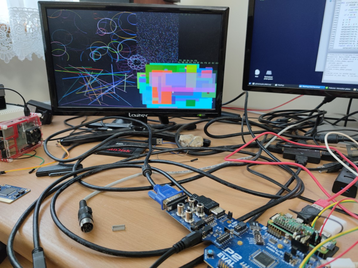
My 4 bit PSRAM (single chip) driver seems to be working with VGA now. Still testing but happy to see this working already. P2 is running at 252MHz here. PSRAM is clocking out nibbles at 126MHz (or 63MB/s).
Wow, SVGA and XGA also work at 8bpp. Neat! P2 is at 325MHz below.
Ignore the ghosted text, the screen was updating rapidly while I took the photo.
Very impressive. With this example, I think it could work with even less bandwidth if the text is generated on the fly in the prop with display list to organize it all. It's a tradeoff of memory bandwidth vs cog power and complexity. I'm curious, how much bandwidth is left over in the blank time?
@pik33 said:
I tried to attach and run the driver from Basic code @ 354 MHz - it works, but I had to rename "read" function as the Basic compiler didn't allow to use that name ("read" is a reserved word) - I think Basic should not complain at names uses in classes, but it did.
Edit: experimental speed is over 73 MB/s - what is the memory clock at sysclock=354 MHz?
Edit2: while the thing works with Eval, it has problems with Edge+breakout board. The video demo displays artefacts and no delay setting can repair this. Simple test without a video, like this:
const _clkfreq = 354000000
#include "retromachine.bi"
dim mem as class using "psram4.spin2"
let cog = mem.startx(0, 0, 0, -1)
let j=getrnd() and $FF
for i=0 to 1023: poke($50000+i,(i +j )mod 256) : next i
let c=getct()
mem.write($50000,0,1024 )
c=getct()-c: print c :c=getct()
mem.read1($70000,0,1024 )
c=getct()-c: print c
for i=0 to 1023: print peek($70000+i), : next i
work up to 356 MHz on Edge - maybe the video output causes noise or something like this.
Do you have the Edge board with the 32MB of memory yet?
@rogloh said:
My 4 bit PSRAM (single chip) driver seems to be working with VGA now. Still testing but happy to see this working already. P2 is running at 252MHz here. PSRAM is clocking out nibbles at 126MHz (or 63MB/s).
Very impressive. With this example, I think it could work with even less bandwidth if the text is generated on the fly in the prop with display list to organize it all. It's a tradeoff of memory bandwidth vs cog power and complexity.
Yes it is a tradeoff.
I'm curious, how much bandwidth is left over in the blank time?
Yeah that is tricky to know for sure because this particular demo is so dynamic with multiple COGs all accessing the shared PSRAM at different times while the video COG also uses it to read the video data out. There is not really one specific bandwidth value here that could be calculated unless you look at chip select high time per scan line and accumulate it over the whole frame. In theory the dead bus time is only really limited by the driver's servicing overheads and mailbox polling time along with how large or small the request bursts can be made as a proportion of the scan line. If there is a COG requesting access the driver will just start to service it, so it's not going to remain idle here. Given its current feature set it's probably about as efficient as it can be. Probably the only way to go any higher from here is to remove driver overhead cycles by removing functionality but that starts to take away its utility and it becomes a diminishing return, at least for the general purpose video applications. Emulator applications with single COG requests may differ in their needs however and some gains could be made.
Do you have the Edge board with the 32MB of memory yet?
No, I have not. The board is not available here. As I can see it is out of stock in Parallax too, and then it is too expensive (now - if they will be in stock in PL, if the war will not reach us and the robot project restarts, I will be able and I will buy several of these). That's why I wanted this 4bit driver as I have PSRAM chips bought and ready to play.
This small 8-pin breakout board I used for these PSRAMs can be soldered into these holes in Edge breakout which can shorten the path a lot, maybe I will try this too as I prepared 10 of these boards.
if the text is generated on the fly in the prop
In my DL driver it is generated on the fly, so if the font definition is placed in the hub ram, I have to read 120 longs per line at 960x540, 35.4 MHz pixel clock, 31.5 kHz horizontal sync - to display 256-color text mode One character is one long, with 16 bit for character code, 8 bit foreground color and 8 bit background.
The maximum resolution for P2 HDMI I can do is 1024x576 at the same 34.5 MHz pixel clock, which should be doable at 8bpp with 73 MB/s bandwidth without any problems. I have now to rewrite the DL driver to enable this...
I also have to try these "N" chips
Edit: I tried the PSRAM modified (old) version of the tracker player. The PSRAM is not reliable in Eval at 354 MHz - the audio is noisy and distorted, while at 320 MHz it plays clean. This something about 320 MHz seems to be the real maximum for these RAMs - testing needed.
I wrote a simple test
const _clkfreq = 350_000_000

#include "retromachine.bi"
dim mem as class using "psram4.spin2"
let cog = mem.startx(0, 0, 13, -1)

let totalres=0 : let totalblock=0
for i=0 to 8191
  for k=0 to 1023: let l=getrnd() and $FF : poke($50000+i,l) : next k
  mem.write($50000,i*1024,1024 )
  for k=0 to 1023 : poke ($70000+k,0) : next k
  mem.read1($70000,i*1024,1024 )
  let res=0
  for k=0 to 1023: if peek($70000+k)<>peek($50000+k) then res+=1
  next k
  totalres+=res
  if res>0 then totalblock+=1
  print "Block "; i;" tested with ";res;" errors "
next i
print "Total errors ";totalres;" in ";totalblock;" blocks"
which allows to testing the RAM and change clock and delay. In these conditions the RAM "ends" somewhere about 350 MHz at delay=13. I don't know (yet?) how to properly slow down the driver to clk/4 or maybe clk/3: the driver is complex.
I managed to slow the driver to CLK/4: it is now stable until the P2 is stable and works at 354 MHz with delay=11. Modules are not played well in any driver and clock settings, there are always distortion: the delay is too high. The PSRAM enabled player is however 0.10, and this is very old and unoptimized version. I think the samples have to be preloaded in bursts to save some time.
I don't know if CLK/3 is even possible here, wxpin #1 gives clk/2, wxpin #2 gives clk/4, time to look into the P2 hardware manual. CLK/4 is too slow to enable HDMI display at any resolution, as it is always CLK/10
@pik33 said:
Edit: I tried the PSRAM modified (old) version of the tracker player. The PSRAM is not reliable in Eval at 354 MHz - the audio is noisy and distorted, while at 320 MHz it plays clean. This something about 320 MHz seems to be the real maximum for these RAMs - testing needed.
I've not overclocked it too much above 320MHz so it might start to fail somewhere around there, also depending on your particular RAM and board wiring etc. It is only rated to 133MHz so overclocking over 160MHz is pushing it hard.
I wrote a simple test
const _clkfreq = 350_000_000

#include "retromachine.bi"
dim mem as class using "psram4.spin2"
let cog = mem.startx(0, 0, 13, -1)

let totalres=0 : let totalblock=0
for i=0 to 8191
  for k=0 to 1023: let l=getrnd() and $FF : poke($50000+i,l) : next k
  mem.write($50000,i*1024,1024 )
  for k=0 to 1023 : poke ($70000+k,0) : next k
  mem.read1($70000,i*1024,1024 )
  let res=0
  for k=0 to 1023: if peek($70000+k)<>peek($50000+k) then res+=1
  next k
  totalres+=res
  if res>0 then totalblock+=1
  print "Block "; i;" tested with ";res;" errors "
next i
print "Total errors ";totalres;" in ";totalblock;" blocks"
There is a bug in your memory randomization loop I think, it should be poke($50000+k,l) I imagine.
I managed to slow the driver to CLK/4: it is now stable until the P2 is stable and works at 354 MHz with delay=11. Modules are not played well in any driver and clock settings, there are always distortion: the delay is too high. The PSRAM enabled player is however 0.10, and this is very old and unoptimized version. I think the samples have to be preloaded in bursts to save some time.
Yes I expected that this will be needed, the latency for single samples will be too challenging unless the audio driver has a lot of free time to wait. It is better to transfer in bursts or use the request list feature to transfer multiple blocks from different external address locations in the single request issued (for multiple channel's samples) while you process in parallel. The documentation explains the request list structures and their capabilities. You just build up a list of the blocks to be transferred (separate source/dest/length), and the driver does it all as fast as it can without the overhead of polling mailbox multiple times etc.
I don't know if CLK/3 is even possible here, wxpin #1 gives clk/2, wxpin #2 gives clk/4, time to look into the P2 hardware manual. CLK/4 is too slow to enable HDMI display at any resolution, as it is always CLK/10
CLK/3 is probably not reliable in my view because the duty cycle requirements of the PSRAM clock signal will be exceeded. CLK/4 is going to be too slow for HDMI video as you point out. If you need higher bandwidth for HDMI the x16 RAM format used on the P2 Edge 32MB is probably a good option (along with /4 CLK if needed at the highest P2 speeds you are using).
I don't know now how to achieve it, as it is impossible with this CLK smart pin setting. I thought about changing the CLK pin mode to NCO frequency, then clk/3 may be possible but the stability may be poor (phase!) and then the driver depends on CLK pulse count.
I have to experiment with my HDMI driver which I know how to modify The idea is to left the driver as it is and add the "PSRAM preload" DL command, so it can preload a line from PSRAM to HUB and the next DL command can point to it. After that I can determine the maximum reliable speed in the real conditions. I tried to do this with your video demo when the Edge displayed garbage, trying to slow down the clock, but my monitor refused to display anything different than 60 Hz ("not supported") with VGA (and it can display near anything when using HDMI - strange beast...)
Best way is change the transition mode (%00101) smartpin into pulse mode (%00100). This allows defining an uneven pulse duty.
But it'll have knock-on effects. Firstly, the clock WYPIN changes from two steps per bit time to one pulse per bit time. Easy to adjust but have to know/find all relevant instructions in the source code.
Secondly, the clock smartpin's internal period is now a metronomic three sysclock instead of one. This is maybe of critical importance to aligning software triggers, which depends on how the software and hardware interact. Possibly doesn't apply with this driver.
I've not really wanted to even attempt the divide by 3 clock, given its duty cycle violation is very significant and the trouble of going back and adjusting various instruction sequence timings as well. It would need to be a different code path. In comparison dividing by 2 or 4 is a lot easier.
Having a better monitor at the university I experimented with frequencies using the video demo. The PSRAM works OK at 340 MHz, then it starts to give up (sporadic white lines). 340/2= 170 MHz and this is a massive overclock for this 133 MHz chip.
The datasheet tells these chips are faster at the lower power supply voltage - maybe adding a serial Shottky diode with 0.4V drop and using bitdac to lower the high logic state can speed them up a bit?
The amount of overclocking available is just down to PCB layout. A wide ground plane and short data paths is the answer. With SDR, highest strength demand is on the clock signal. So there's a reasonable chance you are limited by the prop2's pin drive strength of the SPI clock pin. With DDR, everything is even strength wise.
Other possibilities for limitations might be reflections or ground bounce.
Howdy folks,
I hooked up a PSRAM64H to try the vga driver and only was able to get a garbled output - pls see screenshot (640x480x8)
It looks like its almost working - but not fully. Tried with a second psram64h and got the same result Any ideas what could be wrong?
Cheers!
This is with my VGA demo, or your own code? The pattern almost indicates a skew setting problem or a data bit is stuck/floating possibly? What resolution timing are you using here?ok 640x480.
The latest zip file I posted in this thread uses 1024x768 if that works any better for you.
Make sure you are using the correct PSRAM driver for your setup (etiher the latest beta of a single 4 bit PSRAM for single chips, or the original x16 version I made back in December if you had 4 chips) and the data pins are wired in the right order (must be starting on a nibble boundary) and you've setup the pin numbers correctly in the driver.
Yes, I'm using the latest psram4_demo.zip (0.92b 3 MAR 2022) and the p2videodrv is v0.93b 22 DEC 2021.
Cabling is correct and pin settings are
VGA_BASE_PIN = 28
VGA_VSYNC_PIN = 27
DATABUS = 40
CLK_PIN = 44
CE_PIN = 45
Maybe the 0.93b p2driver is not thew right one?
Could you perhaps make a ZIP file with all needed sources?
@aaaaaaaargh said:
Yes, I'm using the latest psram4_demo.zip (0.92b 3 MAR 2022) and the p2videodrv is v0.93b 22 DEC 2021.
Cabling is correct and pin settings are
VGA_BASE_PIN = 28
VGA_VSYNC_PIN = 27
DATABUS = 40
CLK_PIN = 44
CE_PIN = 45
Maybe the 0.93b p2driver is not thew right one?
Could you perhaps make a ZIP file with all needed sources?
Those files should be okay together but I will try to test them together specifically, in the meantime I notice you are using the P28-P31 for VGA which I don't typically use. VGA on these pins should be okay but on the P2-EVAL there is an issue with high speed activity on those pins causing PLL noise. So if you are using the P2-EVAL give another group of pins a go for VGA if you can. It may help.
In this file to workaround the uninitialized data bug you could replace this block:
{
    ' TODO: fix this for 4 bit PSRAM driver stuff...

    cogBurstLimit := mem.getBurst() - XSIZE*((BPP+7)/8) - MARGIN
    if cogBurstLimit < 0
        DEBUG("No write bandwidth left for reliable video")
        repeat
}
with something like this to get it stable cogBurstLimit := 64
Also the other thing I was thinking is maybe your PSRAMs have a shorted or floating pin or something, there seems to be some sort of wrapping artifact showing, but I can't make sense of what the pattern is. If you just remove the demo drawing portion and clear the screen and then write byte data into the appropriate video frame buffer addresses to create a bounding box in video memory using different colours per screen edge it might help give away the wrapping pattern there, maybe.
Doesn't have to be. VSYNC is a fully independent in my driver, the base should be on a 4 pin boundary. Although if you use the Parallax A/V breakout, yes it should be.
@evanh said:
Shouldn't VGA_BASE_PIN = 24 and VGA_VSYNC_PIN = 28 when using an Eval Board?
I'm using the P2 Retroblade, this is how the onboard vga socket is wired.
VGA_BASE_PIN = 28 , VGA_VSYNC_PIN = 27
Anyway I think the problem might be signal degradation related. I'm trying to use the psram on a breadboard, and as soon as my hand gets close to the chip or the jumper cables the whole picture disappears completely and doesn't come back, who knows what commands are send to the psram then...
I had such great results with my breadboard sram vga setup that I though it might work with psram as well. I guess I'll have to make a litte ram backpack like the one @pik33 made earlier in this thread to get better results...
@aaaaaaaargh said:
Anyway I think the problem might be signal degradation related. I'm trying to use the psram on a breadboard, and as soon as my hand gets close to the chip or the jumper cables the whole picture disappears completely and doesn't come back, who knows what commands are send to the psram then...
I had such great results with my breadboard sram vga setup that I though it might work with psram as well. I guess I'll have to make a litte ram backpack like the one @pik33 made earlier in this thread to get better results...
Yes these are high speed signals around ~ 125MHz and the signal quality needs to be high, so a breadboard very likely won't cut it any more. It sounds like that might be the issue. In my setup I can wave my hands around the PSRAM and it is fine, but I have my own circuit board that was designed for PSRAM that fits the P2-EVAL. You might be able to make yourself a PCB for the Retroblade and use it as a plug in backpack type of board. Should be a fairly simple board to layout with just the 8 pins connected if you want a single chip. Although if you do layout a board, it might be worth allowing for the 4 device option too with a 16 bit bus - there should be plenty of space for fitting 4 chips. Include a bypass cap per chip and you can share the clock and CS pins over all devices or wire them separately to allow even more flexibility. My driver allows for both options if you keep the CLK and CS pins grouped sequentially so they can be controlled in the same DRVL instruction using a pin group. This is beneficial because you could either setup dedicated PSRAMs per COG for emulator use for example, or have a shared one (with higher speed) for multiple COGs, eg. video use.
@evanh said:
ewww, Roger, I'm just having a nosey at your driver doc, MemoryDriverDocumentation_v09b.pdf, and trying to work out how to use it and how Ada has used it ... not matching up very well so far. The first function Ada's code calls is "getDriverAddr()" but that isn't even a documented function!
Answering here in this related thread instead of Ada's console emulation thread.
I think that is because there are now multiple drivers in the bundle, and the main documentation was originally written for the full blown driver which can handle the cases of multiple disparate memory buses and multiple driver COGs in the same system. In this latest release, now that it supports more than just HyperRAM/HyperFlash memory types, I have supplied some additional trimmed down drivers to support dedicated single memory bus systems (e.g, for P2-EC32MB) which then have a smaller footprint and can also be slightly simpler to setup. The supplied documentation should still cover the full blown driver with any luck, but currently neglects going into details for these cut down driver(s) and other internal APIs, and relies on people reading through the sample code to help figure it out. Some of this is mentioned in the Release Notes. If I ever put more attention into wrapping up the documentation it should be improved, but when that will be is unknown.
I have a general problem with these memory drivers in that if I create a superset of every API in a common driver its size will then bloat quite a bit in PropTool due to not having dead code removal (although FlexSpin is okay). Eg, you could get HyperFlash APIs included in the binary when you only use PSRAM etc. I also don't really want to duplicate driver code over and over in lots of small files either, as that is a pain to maintain and test when there are changes. So I'm a bit stuck until I figure out a good compromise there. Am sort of vainly hoping Chip will include dead code removal one day. I know he wants to but not sure if it's that easy for him to put into the tools.


Comments
A question:
An idea
The advantage: using exactly and only one pin bank. Connecting one PSRAM chip uses 6 pins and these 2 pins left will be practically wasted
The disadvandage: low bandwidth.
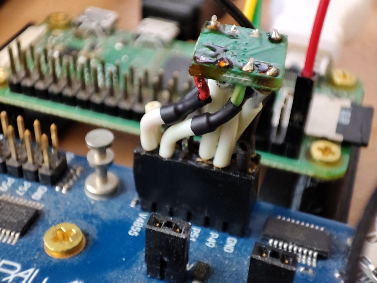
The contraption works!
I already split up the bursts that cross 1kB boundaries into different transactions, so that is not an issue.
This already should be supported with my original memory driver. That can handle multiple mapped devices on the same bus or different buses, with heterogeneous memory buses allowed as well. Each memory device gets its own chip select and can be mapped to a different region of the address space. So with 3 devices you could have 24MB of PSRAM memory.
To be tested in the future") I bought 30 these chips some time ago so I have a room for experiments. The robot project stopped due to bureaucratic problems and I have some more free time to play.
I bought 30 these chips some time ago so I have a room for experiments. The robot project stopped due to bureaucratic problems and I have some more free time to play.
Now as I managed to solder a working contraption I have to solder the second one to use at the university and then learn how to use the driver and adapt it to my HDMI and the player stuff. I have to extend the displaylist now to enable getting the line from PSRAM, so the driver can be flexible and get every line from where it wants to.
To use the driver from PASM once it's all been initialized, it's really easy from a client COG...you just do this:
setq #2 ' send 3 longs to our 12 byte mailbox wrlong extmemAddr, mailboxAddr ' issue the request .... ' can go do some work here while the transfer happens in the background rdlong ina, mailboxAddr wc ' optional test for completion (though it may not make sense to actually wait for video results, also ATN could optionally be used instead) if_c jmp #$-1 ' wait for completion .... ' 3 contiguous longs in COG RAM to send to mailbox as request extMemAddr long $B000000 ' external memory address you want to read from with top nibble set to $B for a burst read hubMemAddr long $4444 ' some hub RAM address buffer to read into transferSize long 1024 ' size of scan line data to read in bytesNote there is some latency before the external memory contents is delivered into hub RAM once you make the request. This varies based on any other lower priority COG's PSRAM activity completing (duration is affected by the COG's burst size setting), the polling overhead time, some internal driver request servicing overheads, and PSRAM address header overheads. At a minimum this could be in the order of at least 1usec if there are no other COGs accessing the RAM. I handle this by requesting the scan line data one line earlier so it is all fully ready in memory by the time it needs to be streamed out letting me add a mouse sprite as well. In your driver maybe you could issue the request at the end of the prior scan line (during horizontal front porch). So you have the entire blanking interval before data needs to be sent and that could be some microseconds. It can overlap the transfers if the PSRAM delivers data faster than the graphics bandwidth needed.
Before I will try and use PSRAMs (tomorrow... too tired today) I printed a box for the device. Now it looks much better and safer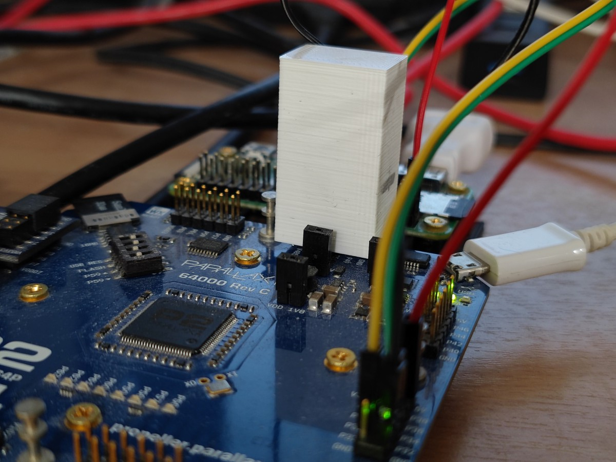
I tried to attach and run the driver from Basic code @ 354 MHz - it works, but I had to rename "read" function as the Basic compiler didn't allow to use that name ("read" is a reserved word) - I think Basic should not complain at names uses in classes, but it did.
Edit: experimental speed is over 73 MB/s - what is the memory clock at sysclock=354 MHz?
Edit2: while the thing works with Eval, it has problems with Edge+breakout board. The video demo displays artefacts and no delay setting can repair this. Simple test without a video, like this:
work up to 356 MHz on Edge - maybe the video output causes noise or something like this.
Yeah that is a problem if the language name space collides between different object's method names. If the object's name is used it should be able to resolve the difference between reserved words and method names in embedded classes. Maybe let Eric know.
Memory clock for PSRAM is half the P2 clock so it would be overclocked at 172MHz from its rated 133-143MHz, just as the P2 is being massively overclocked at 354MHz. In time it could be possible to allow to a quarter speed clock but that would halve performance.
A breakout board for the Edge will likely affect timing at that clock speed as well as interfere if high speed video is on the breakout as well. I already know the JonnyMac board is not going to work out at high speed with it's long traces. If you want to use PSRAM with a P2 Edge you are probably best placed to obtain the integrated P2-EC32MB Edge which will have 16 bit wide PSRAM with well constrained timing, or at least design you own Edge attached board that keeps different high speed traces for video and PSRAM well separated and length matched etc.
Very impressive. With this example, I think it could work with even less bandwidth if the text is generated on the fly in the prop with display list to organize it all. It's a tradeoff of memory bandwidth vs cog power and complexity. I'm curious, how much bandwidth is left over in the blank time?
Do you have the Edge board with the 32MB of memory yet?
Yes it is a tradeoff.
Yeah that is tricky to know for sure because this particular demo is so dynamic with multiple COGs all accessing the shared PSRAM at different times while the video COG also uses it to read the video data out. There is not really one specific bandwidth value here that could be calculated unless you look at chip select high time per scan line and accumulate it over the whole frame. In theory the dead bus time is only really limited by the driver's servicing overheads and mailbox polling time along with how large or small the request bursts can be made as a proportion of the scan line. If there is a COG requesting access the driver will just start to service it, so it's not going to remain idle here. Given its current feature set it's probably about as efficient as it can be. Probably the only way to go any higher from here is to remove driver overhead cycles by removing functionality but that starts to take away its utility and it becomes a diminishing return, at least for the general purpose video applications. Emulator applications with single COG requests may differ in their needs however and some gains could be made.
No, I have not. The board is not available here. As I can see it is out of stock in Parallax too, and then it is too expensive (now - if they will be in stock in PL, if the war will not reach us and the robot project restarts, I will be able and I will buy several of these). That's why I wanted this 4bit driver as I have PSRAM chips bought and ready to play.
This small 8-pin breakout board I used for these PSRAMs can be soldered into these holes in Edge breakout which can shorten the path a lot, maybe I will try this too as I prepared 10 of these boards.
In my DL driver it is generated on the fly, so if the font definition is placed in the hub ram, I have to read 120 longs per line at 960x540, 35.4 MHz pixel clock, 31.5 kHz horizontal sync - to display 256-color text mode One character is one long, with 16 bit for character code, 8 bit foreground color and 8 bit background.
The maximum resolution for P2 HDMI I can do is 1024x576 at the same 34.5 MHz pixel clock, which should be doable at 8bpp with 73 MB/s bandwidth without any problems. I have now to rewrite the DL driver to enable this...
I also have to try these "N" chips
Edit: I tried the PSRAM modified (old) version of the tracker player. The PSRAM is not reliable in Eval at 354 MHz - the audio is noisy and distorted, while at 320 MHz it plays clean. This something about 320 MHz seems to be the real maximum for these RAMs - testing needed.
I wrote a simple test
which allows to testing the RAM and change clock and delay. In these conditions the RAM "ends" somewhere about 350 MHz at delay=13. I don't know (yet?) how to properly slow down the driver to clk/4 or maybe clk/3: the driver is complex.
I managed to slow the driver to CLK/4: it is now stable until the P2 is stable and works at 354 MHz with delay=11. Modules are not played well in any driver and clock settings, there are always distortion: the delay is too high. The PSRAM enabled player is however 0.10, and this is very old and unoptimized version. I think the samples have to be preloaded in bursts to save some time.
I don't know if CLK/3 is even possible here, wxpin #1 gives clk/2, wxpin #2 gives clk/4, time to look into the P2 hardware manual. CLK/4 is too slow to enable HDMI display at any resolution, as it is always CLK/10
I've not overclocked it too much above 320MHz so it might start to fail somewhere around there, also depending on your particular RAM and board wiring etc. It is only rated to 133MHz so overclocking over 160MHz is pushing it hard.
There is a bug in your memory randomization loop I think, it should be
poke($50000+k,l)I imagine.Yes I expected that this will be needed, the latency for single samples will be too challenging unless the audio driver has a lot of free time to wait. It is better to transfer in bursts or use the request list feature to transfer multiple blocks from different external address locations in the single request issued (for multiple channel's samples) while you process in parallel. The documentation explains the request list structures and their capabilities. You just build up a list of the blocks to be transferred (separate source/dest/length), and the driver does it all as fast as it can without the overhead of polling mailbox multiple times etc.
CLK/3 is probably not reliable in my view because the duty cycle requirements of the PSRAM clock signal will be exceeded. CLK/4 is going to be too slow for HDMI video as you point out. If you need higher bandwidth for HDMI the x16 RAM format used on the P2 Edge 32MB is probably a good option (along with /4 CLK if needed at the highest P2 speeds you are using).
I don't know now how to achieve it, as it is impossible with this CLK smart pin setting. I thought about changing the CLK pin mode to NCO frequency, then clk/3 may be possible but the stability may be poor (phase!) and then the driver depends on CLK pulse count.
I have to experiment with my HDMI driver which I know how to modify") The idea is to left the driver as it is and add the "PSRAM preload" DL command, so it can preload a line from PSRAM to HUB and the next DL command can point to it. After that I can determine the maximum reliable speed in the real conditions. I tried to do this with your video demo when the Edge displayed garbage, trying to slow down the clock, but my monitor refused to display anything different than 60 Hz ("not supported") with VGA (and it can display near anything when using HDMI - strange beast...)
The idea is to left the driver as it is and add the "PSRAM preload" DL command, so it can preload a line from PSRAM to HUB and the next DL command can point to it. After that I can determine the maximum reliable speed in the real conditions. I tried to do this with your video demo when the Edge displayed garbage, trying to slow down the clock, but my monitor refused to display anything different than 60 Hz ("not supported") with VGA (and it can display near anything when using HDMI - strange beast...)
Best way is change the transition mode (%00101) smartpin into pulse mode (%00100). This allows defining an uneven pulse duty.
But it'll have knock-on effects. Firstly, the clock WYPIN changes from two steps per bit time to one pulse per bit time. Easy to adjust but have to know/find all relevant instructions in the source code.
Secondly, the clock smartpin's internal period is now a metronomic three sysclock instead of one. This is maybe of critical importance to aligning software triggers, which depends on how the software and hardware interact. Possibly doesn't apply with this driver.
I've not really wanted to even attempt the divide by 3 clock, given its duty cycle violation is very significant and the trouble of going back and adjusting various instruction sequence timings as well. It would need to be a different code path. In comparison dividing by 2 or 4 is a lot easier.
Having a better monitor at the university I experimented with frequencies using the video demo. The PSRAM works OK at 340 MHz, then it starts to give up (sporadic white lines). 340/2= 170 MHz and this is a massive overclock for this 133 MHz chip.
The datasheet tells these chips are faster at the lower power supply voltage - maybe adding a serial Shottky diode with 0.4V drop and using bitdac to lower the high logic state can speed them up a bit?
The amount of overclocking available is just down to PCB layout. A wide ground plane and short data paths is the answer. With SDR, highest strength demand is on the clock signal. So there's a reasonable chance you are limited by the prop2's pin drive strength of the SPI clock pin. With DDR, everything is even strength wise.
Other possibilities for limitations might be reflections or ground bounce.
Howdy folks,
I hooked up a PSRAM64H to try the vga driver and only was able to get a garbled output - pls see screenshot (640x480x8)
It looks like its almost working - but not fully. Tried with a second psram64h and got the same result Any ideas what could be wrong?
Cheers!
This is with my VGA demo, or your own code? The pattern almost indicates a skew setting problem or a data bit is stuck/floating possibly? What resolution timing are you using here?ok 640x480.
The latest zip file I posted in this thread uses 1024x768 if that works any better for you.
Make sure you are using the correct PSRAM driver for your setup (etiher the latest beta of a single 4 bit PSRAM for single chips, or the original x16 version I made back in December if you had 4 chips) and the data pins are wired in the right order (must be starting on a nibble boundary) and you've setup the pin numbers correctly in the driver.
Yes, I'm using the latest psram4_demo.zip (0.92b 3 MAR 2022) and the p2videodrv is v0.93b 22 DEC 2021.
Cabling is correct and pin settings are
VGA_BASE_PIN = 28
VGA_VSYNC_PIN = 27
DATABUS = 40
CLK_PIN = 44
CE_PIN = 45
Maybe the 0.93b p2driver is not thew right one?
Could you perhaps make a ZIP file with all needed sources?
Those files should be okay together but I will try to test them together specifically, in the meantime I notice you are using the P28-P31 for VGA which I don't typically use. VGA on these pins should be okay but on the P2-EVAL there is an issue with high speed activity on those pins causing PLL noise. So if you are using the P2-EVAL give another group of pins a go for VGA if you can. It may help.
I also wonder, did the slightly earlier zip file I posted here: https://forums.parallax.com/discussion/comment/1536385/#Comment_1536385 work for you if you tried that as well? It did have a bug but it worked for me and I know @pik33 has had some success here too.
In this file to workaround the uninitialized data bug you could replace this block:
{ ' TODO: fix this for 4 bit PSRAM driver stuff... cogBurstLimit := mem.getBurst() - XSIZE*((BPP+7)/8) - MARGIN if cogBurstLimit < 0 DEBUG("No write bandwidth left for reliable video") repeat }with something like this to get it stable
cogBurstLimit := 64Also the other thing I was thinking is maybe your PSRAMs have a shorted or floating pin or something, there seems to be some sort of wrapping artifact showing, but I can't make sense of what the pattern is. If you just remove the demo drawing portion and clear the screen and then write byte data into the appropriate video frame buffer addresses to create a bounding box in video memory using different colours per screen edge it might help give away the wrapping pattern there, maybe.
Shouldn't VGA_BASE_PIN = 24 and VGA_VSYNC_PIN = 28 when using an Eval Board?
Doesn't have to be. VSYNC is a fully independent in my driver, the base should be on a 4 pin boundary. Although if you use the Parallax A/V breakout, yes it should be.
Yeah, that's what I meant ... but I guess he could be using something else plugged into the actual Eval Board.
I'm using the P2 Retroblade, this is how the onboard vga socket is wired.
VGA_BASE_PIN = 28 , VGA_VSYNC_PIN = 27
Anyway I think the problem might be signal degradation related. I'm trying to use the psram on a breadboard, and as soon as my hand gets close to the chip or the jumper cables the whole picture disappears completely and doesn't come back, who knows what commands are send to the psram then...
I had such great results with my breadboard sram vga setup that I though it might work with psram as well. I guess I'll have to make a litte ram backpack like the one @pik33 made earlier in this thread to get better results...
Yes these are high speed signals around ~ 125MHz and the signal quality needs to be high, so a breadboard very likely won't cut it any more. It sounds like that might be the issue. In my setup I can wave my hands around the PSRAM and it is fine, but I have my own circuit board that was designed for PSRAM that fits the P2-EVAL. You might be able to make yourself a PCB for the Retroblade and use it as a plug in backpack type of board. Should be a fairly simple board to layout with just the 8 pins connected if you want a single chip. Although if you do layout a board, it might be worth allowing for the 4 device option too with a 16 bit bus - there should be plenty of space for fitting 4 chips. Include a bypass cap per chip and you can share the clock and CS pins over all devices or wire them separately to allow even more flexibility. My driver allows for both options if you keep the CLK and CS pins grouped sequentially so they can be controlled in the same DRVL instruction using a pin group. This is beneficial because you could either setup dedicated PSRAMs per COG for emulator use for example, or have a shared one (with higher speed) for multiple COGs, eg. video use.
Answering here in this related thread instead of Ada's console emulation thread.
I think that is because there are now multiple drivers in the bundle, and the main documentation was originally written for the full blown driver which can handle the cases of multiple disparate memory buses and multiple driver COGs in the same system. In this latest release, now that it supports more than just HyperRAM/HyperFlash memory types, I have supplied some additional trimmed down drivers to support dedicated single memory bus systems (e.g, for P2-EC32MB) which then have a smaller footprint and can also be slightly simpler to setup. The supplied documentation should still cover the full blown driver with any luck, but currently neglects going into details for these cut down driver(s) and other internal APIs, and relies on people reading through the sample code to help figure it out. Some of this is mentioned in the Release Notes. If I ever put more attention into wrapping up the documentation it should be improved, but when that will be is unknown.
I have a general problem with these memory drivers in that if I create a superset of every API in a common driver its size will then bloat quite a bit in PropTool due to not having dead code removal (although FlexSpin is okay). Eg, you could get HyperFlash APIs included in the binary when you only use PSRAM etc. I also don't really want to duplicate driver code over and over in lots of small files either, as that is a pain to maintain and test when there are changes. So I'm a bit stuck until I figure out a good compromise there. Am sort of vainly hoping Chip will include dead code removal one day. I know he wants to but not sure if it's that easy for him to put into the tools.
Got it, smaller drivers aren't specifically documented. Actually, the document doesn't name any files at all. Probably need to add something for that.
Right, looks like "psram.spin2" is good example use of "psram16drv.spin2".